background image

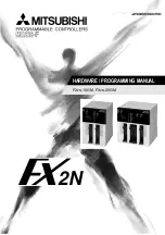
HARDWARE / PROGRAMMING MANUAL

FX

2N

-10GM, FX

2N

-20GM

Содержание FX2N-10GM

Страница 1: ...HARDWARE PROGRAMMING MANUAL FX2N 10GM FX2N 20GM ...

Страница 2: ...f FX2N 10GM FX2N 20GM unit this manual should be read and understood If in doubt at any stage of the installation of the communication facilities of FX2N 10GM FX2N 20GM units always consult a professional electrical engineer who is qualified and trained to the local and national standards which apply to the installation site If in doubt about the operation or use of the communication facilities of...

Страница 3: ...i FX2N 10GM FX2N 20GM Hardware Programming Manual Manual number JY992D77801 Manual revision B Date February 2000 FX Series Positioning Controllers ...

Страница 4: ...FX Series Positioning Controllers ii ...

Страница 5: ...7 278 695 Please tick the box of your choice What condition did the manual arrive in Good Minor damage Unusable Will you be using a folder to store the manual Yes No What do you think to the manual presentation Tidy Un friendly Are the explanations understandable Yes Not too bad Unusable Which explanation was most difficult to understand Are there any diagrams which are not clear Yes No If so whic...

Страница 6: ...FX Series Positioning Controllers iv ...

Страница 7: ...rs of the completed equipment should be trained to use that product in a safe and coordinated manner in compliance to established safety practices The operators should also be familiar with documentation which is connected with the actual operation of the completed equipment Note Note the term completed equipment refers to a third party constructed device which contains or uses the product associa...

Страница 8: ...pment All examples and diagrams shown in this manual are intended only as an aid to understand ing the text not to guarantee operation Mitsubishi Electric will accept no responsibility for actual use of the product based on these illustrative examples Owing to the very great variety in possible application of this equipment you must satisfy yourself as to its suitability for your specific applicat...

Страница 9: ...block 1 25 1 7 4 Internal connection diagram of terminal block 1 26 1 7 5 Terminal block layout 1 31 2 Specifications 2 1 2 1 Power Supply Specifications 2 1 2 2 General Specifications 2 1 2 3 Performance Specifications 2 1 2 4 Input Specification 2 4 2 5 Output Specification 2 6 3 Wiring 3 1 3 1 Wiring of Power Supply 3 1 3 2 Wiring of I O 3 5 3 2 1 Example of wiring of input 3 5 3 2 2 Output con...

Страница 10: ...TC Center point compensation cod 75 RADC Radius compensation 5 36 5 6 14 cod 76 CANC Compensation cancel 5 37 5 6 15 cod 90 ABS Absolute address cod 91 INC Incremental address 5 38 5 6 16 cod 92 SET Present value change 5 39 5 7 Common Items in Sequence Control Instructions 5 40 5 7 1 Difference in operation by PLC 5 40 5 7 2 Applicable devices 5 41 5 7 3 Bit devices 5 42 5 7 4 Data length and ins...

Страница 11: ... stop 7 7 7 3 3 Reading the present value 7 8 7 3 4 Setting the travel and the operation speed 7 9 7 3 5 Reading m codes 7 10 7 3 6 Reading Changing the parameters 7 12 7 4 Positioning using the table method FX2N 10GM 7 13 7 4 1 Outline of the table function 7 13 7 4 2 Declaration of table method 7 13 7 4 3 Assignment of table data 7 14 7 4 4 Setting of table data 7 15 8 Operation Maintenance and ...

Страница 12: ...GM FX2N 20GM 9 13 9 3 8 Operation at multi step speed independent operation 9 14 9 4 Simultaneous 2 Axis Position Control Operation FX2N 10GM 9 16 9 4 1 Positioning by constant quantity of reciprocating motion FX2N 20GM 9 16 9 4 2 Linear interpolation FX2N 20GM 9 18 9 4 3 Circular interpolation true circle FX2N 20GM 9 19 9 4 4 Interrupt stop FX2N 20GM 9 20 9 4 5 Continuous pass operation FX2N 20GM...

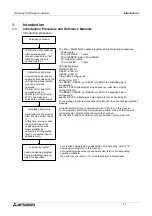
Страница 13: ...r by performing JOG operation from a connected input or peripheral unit Loading of program Load a positioning program from a peripheral unit and adjust the operation Correctly perform wiring in accordance with 3 Wiring in this manual For an operation which may cause danger perform wiring so that the unit conservatively operates when the power is shut down Set interlock to positions which should no...

Страница 14: ...the table method 3 Manual pulse generator Manual feed is enabled when a general purpose manual pulse generator open collector type is connected 4 Absolute position ABS detection Returning to the zero point at every startup can be saved when a servo amplifier equipped with absolute position ABS detection function is connected 5 Connected PLC Positioning data can be read written when an FX2N 2NC Ser...

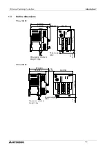
Страница 15: ...74 2 91 13 0 51 87 3 43 Power supply cable Dimensions mm inch Weight 0 3kg SVRDY X LSR LSF CLR RP FP PG0 SVEND SVRDY Y Y6 Y7 X0 X2 X3 X4 X5 X6 Y0 Y1 Y2 Y3 X1 Y5 X7 Y4 AUTO MANU POWER ERROR y CPU E PG0 FP RP CLR SVEND LSR LSF DOG RVS FWD ZRN STOP START Y 6 7 X0 2 3 X4 5 6 Y0 1 2 3 1 5 7 Y4 BATT READY x ERROR x READY y DOG RVS START X STOP ZRN FWD 90 3 54 86 3 39 13 0 51 74 2 91 13 0 51 87 3 43 FX 2...

Страница 16: ... purpose I O display o Connector for input equipment CON2 f Display for equipment inputs p Connector for power supply g x axis status display q Connector for general purpose I O CON1 h Lock to fix extension block of FX2N 20GM r Connector for memory board i y axis status display s Connector for PLC j Connector for FX2N 20GM extension block ZRN FWD Y4 Y5 RP STOP FP X2 X3 Y0 Y1 Y2 START Y3 CLR AUTO M...

Страница 17: ...en attaching it to the DIN rail An extension block cannot be connected to the FX2N 10GM 1 4 3 MANU AUTO selector switch Set this switch to MANU for manual operation or to AUTO for automatic operation Select the MANU mode when writing programs or setting parameters In the MANU mode positioning programs and subtask programs stop When this switch is changed over from AUTO to MANU during automatic ope...

Страница 18: ...it during installation e g cut wires shavings etc Once installation is complete remove the protective paper band to prevent overheating General notes Always ensure that mounted units and blocks are kept as far as possible from high volt age cables high voltage equipment and power equipment Wiring cautions Do not run input signals in the same multicore cable as output signals or allow them to share...

Страница 19: ... on the right side of the FX2N 20GM I O points cannot be extended to the FX2N 10GM Securely connect cables such as extension cables and memory cassettes to specified connectors Imperfect contact may cause malfunction Turn off the power at first then connect disconnect the cable such as an extension cable If you connect disconnect a cable while the power is supplied the unit may fail or mal functio...

Страница 20: ...one nearest to the PLC the special unit Nos 0 to 7 are automatically assigned to the connected special units This special unit No is used the by FROM TO instructions Separate from I O points in the PLC and general purpose I O points in the FX2N 10GM are controlled as I O points in the FX2N 10GM One PLC occupies eight I O points For the details of assignment of I O points in the PLC refer to the FX...

Страница 21: ...LC main unit make sure that the simultaneous ON ratio is 50 or less in the I O extension area of the FX2N 20GM I O assignment shown inside indicates I O points in the FX2N 10GM X010 to X027 X00 to X07 Y00 to Y07 Y010 to Y027 SVRDY X LSR LSF CLR RP FP PG0 SVEND SVRDY Y Y6 Y7 X0 X2 X3 X4 X5 X6 Y0 Y1 Y2 Y3 X1 Y5 X7 Y4 AUTO MANU POWER ERROR y CPU E PG0 FP RP CLR SVEND LSR LSF DOG RVS FWD ZRN STOP STAR...

Страница 22: ...2N 20GM are con trolled as I O points in the FX2N 20GM One PLC occupies eight I O points For the details of assignment of I O points in the PLC refer to the FX2N 2NC Series Hardware manuals I O extension connector The FX2N 20GM can be connected to an FX2NC Series extension block excluding the relay output type to extend general purpose I O points Or the FX2N 20GM can be connected to an FX2N Series...

Страница 23: ...ile pulses are being output or an error is present READY Y Lit while Y axis of FX2N 20GM is ready for receiving diversified operation commands Extinguished while positioning is per formed by Y axis that is while pulses are being output or an error is present ERROR Lit or flashing when an error has occurred during positioning operation You can read error code on a peripheral unit to check contents ...

Страница 24: ...ay rigid attention to the positions of and notches Perform Class 3 grounding with an electric wire of 2 mm2 or more to the ground terminal in the positioning unit However never perform common grounding with a strong power system CON1 X1 X0 X2 X3 Y0 Y1 Y2 Y3 COM1 COM2 SVRDY CLR COM3 FP VIN VIN COM5 ST1 CON2 COM2 SVEND PG0 COM4 RP VIN VIN COM5 ST2 STOP START ZRN FWD RVS DOG LSF LSR COM1 Y4 Y5 Notch ...

Страница 25: ...hanical zero point return start input manual When ZRN signal turns ON from OFF zero point return command is set and machine starts to return to zero point ZRN signal is reset when return to zero point is fin ished or stop command is given 4 4 Y 14 X FWD Normal rotation input manual When FWD signal turns ON positioning unit generates a forward pulse of minimum command unit When FWD sig nal remains ...

Страница 26: ... CON3 2 12 COM2 Common of SVRDY and SVEND signals X axis 3 CON3 CON4 3 CLR Outputs deviation counter clear signal 4 CON3 4 COM3 Common of CLR signal X axis 6 CON3 CON4 6 FP Normal rotation pulse output 7 8 17 18 7 8 17 18 VIN Input 5 V 24 V for power for FP and RP 9 19 CON3 9 19 COM5 Common of FP and RP signals X axis 10 10 ST1 Short circuit ST1 and ST2 when connecting PG0 to 5 V power supply 11 C...

Страница 27: ... dedicated to I O CON3 Connector to connect a drive unit for the X axis CON4 Connector to connect a drive unit for the Y axis Description of two or more pin Nos shown in the Pin No column such as COM1 COM2 and VIN indicates that such pins are short circuited inside While the FX2N 20GM is performing simultaneous 2 axis operation step mode command start command stop command and m code OFF command ar...

Страница 28: ...ins sold separately e RS 422 cable to connect personal computer packed together with FX PCS KIT GM EE FX 422CAB0 f Cable to connect servo amplifier drive unit sold separately Cable to connect MR C E GMC 200CAB 2 m Cable to connect MR J E GMJ 200CAB 2 m Cable to connect MR J2 E GMJ2 200CAB1A 2 m Cable to connect MR H E GMH 200CAB 2 m Cable to connect general purpose drive unit E GM 200CAB 2 m relay...

Страница 29: ...ith connector on each end 5 0 m FX 16E 150CAB R Round multi core cable with connector on each end 1 5 m FX 16E 300CAB R Round multi core cable with connector on each end 3 0 m FX 16E 500CAB R Round multi core cable with connector on each end 5 0 m FX 16E 500CAB S Cable with connector on only one end 5 0 m h Terminal block sold separately For positioning unit extension block FX 16E TB FX 32E TB For...

Страница 30: ...DIN 8 pin male connector c d e f g h i j MINI DIN 8 pin male connector 1 2 3 4 5 6 7 8 1 2 3 4 5 6 7 8 c d e f g h i j 1 13 14 25 MINI DIN 25 pin male connector 1 13 14 25 MINI DIN 25 pin male connector c d e g h i 20 c d e g h i 20 D SUB 9 pin female connector d e i j f g h 1 5 6 9 1 13 14 25 MINI DIN 25 pin male connector c d e g h i 20 f c k d f d e g h i Half pitch 14 pin connector 1 13 14 25 ...

Страница 31: ... CAB0 1M FX 50DU CAB0 10M FX 50DU CAB0 20M FX 50DU CAB0 30M and FX 50DU CAB0L d e i d i e g c f h g j j MINI DIN 25 pin male connector 1 13 14 25 MINI DIN 8 pin male connector 1 2 3 4 5 6 7 8 12 15 16 20 24 21 18 25 c d f g h i k d i h e c f g 1 2 3 4 5 6 7 8 MINI DIN 9 pin male connector MINI DIN 8 pin male connector 1 5 6 9 ...

Страница 32: ...B 11 1 20 10 Connected to FX 16E TB 11 1 20 10 Pin assignment Connected to CON2 in FX2N 10GM or CON3 CON4 in FX2N 20GM 11 13 15 17 19 12 14 16 18 20 1 3 5 7 9 2 4 6 8 10 Pin assignment Pin assignment COM3 COM7 SVRDY COM2 COM6 COM2 COM6 SVEND COM4 COM8 PG0 VIN VIN COM5 COM9 COM5 COM9 RP CLR FP 24 23 18 22 1 2 12 11 14 12 SD CR NP SG PP VDD OPC OP P15R PF VDD RD 7 6 9 3 13 17 19 35 25 1 12 20 13 32 ...

Страница 33: ...FX2N 20GM Pin assignment Connected to CN1A in servo amplifier MR J2A Cable to connect MR J E GMJ 200CAB Pin assignment COM3 COM7 SVRDY COM2 COM6 COM2 COM6 SVEND COM4 COM8 PG0 VIN VIN COM5 COM9 COM5 COM9 RP CLR FP 49 22 20 19 1 2 12 11 14 14 VIN CR NP0 SG PP0 VDD OP P15R PF VDD RD 7 6 9 3 13 17 19 22 24 1 33 18 47 37 4 17 SG VDD 12 ZSG 48 ALM 1 EMG 2 SON 3 RES 16 15 11 21 23 46 12 11 1 20 10 11 1 2...

Страница 34: ...3 COM5 COM9 1 6 4 1 2 12 11 14 6 19 16 10 13 9 3 2 11 14 13 19 16 10 20 20 4 Connected to drive unit of general purpose servo motor or stepping motor via FX 16E TB 11 1 20 10 Green 0 5 mm VIN VIN 7 7 17 17 VIN VIN 8 8 18 18 5 5 15 15 12 9 3 Shielded cable Class 3 grounding 2 Never use them Connected to CON2 in FX2N 10GM or CON3 CON4 in FX2N 20GM Pin assignment 1 2 3 4 5 6 7 8 9 10 11 12 13 14 15 1...

Страница 35: ...del name and configuration of I O connector Applicable electric wire and tool 1 Model name in Mitsubishi Included parts manufactured by Daiichi Denshi Electric wire size Crimp tool manufactured by Daiichi Denshi FX2C I O CON for flat cable 10 connectors Crimp connector FRC2 A020 30S AWG28 0 1 mm2 1 27 pitch 20 core Main body 357J 4674D Attachment 357J 4664N FX2C I O CON S for unbound wire 5 sets H...

Страница 36: ...t 16 points can be connected to extension block cannot be connected to positioning unit You can use a terminal block for only AC input or for only output to convert a connector type extension block connected to the FX2N 20GM into a terminal block Have in mind that you can not connect such a terminal block to the I O area of the positioning unit For the details of terminal blocks refer to an instru...

Страница 37: ...sistor output Load voltage 250V AC 30V DC or less 85V AC to 242V AC 5V DC to 30V DC 5V DC to 30V DC Circuit insulation Mechanical insula tion Photothyristor insulation Photocoupler insu lation Photocoupler insu lation Operation indica tion While power is supplied to relay coil LED is lit While power is supplied to photo thyristor LED is lit While power is sup plied to photocou pler LED is lit Whil...

Страница 38: ...on 1 1 26 1 7 4 Internal connection diagram of terminal block FX 16E TB 2 4 9 6 8 9 12 14 9 16 18 9 10 20 10 19 9 18 8 17 7 16 6 15 5 14 4 13 3 12 2 11 1 Connector pin No 20 3 9 5 7 9 11 13 9 15 17 9 1 Notch 11 12 13 14 15 16 17 18 Terminal block ...

Страница 39: ...18 8 17 7 16 6 15 5 14 4 13 3 12 2 11 1 20 3 9 5 7 9 11 13 9 15 17 9 1 11 12 13 14 15 16 17 18 2 4 9 6 8 9 12 14 9 16 18 9 10 20 10 19 9 18 8 17 7 16 6 15 5 14 4 13 3 12 2 11 1 20 3 9 5 7 9 11 13 9 15 17 9 1 11 12 13 14 15 16 17 18 Connector pin No Notch Terminal block Connector pin No Notch Terminal block ...

Страница 40: ...1 Photocoupler power supply 1kΩ DC24V 10 15 Service power supply in PC can be used 1 4 5 8 11 14 15 18 Connector pin No Terminal block 2 4 COM 1 6 8 COM 2 12 14 COM 3 16 18 COM 4 24 20 10 19 9 18 8 17 7 16 6 15 5 14 4 13 3 12 2 11 1 24 3 COM 1 5 7 COM 2 11 13 COM 3 15 17 COM 4 1 Power supply for relay DC24V 10 15 3 4 2 1 7 8 6 5 13 14 12 11 17 18 16 15 Service power supply in PC can be used Connec...

Страница 41: ...2 11 17 18 16 15 Surge absorber is connected to each output point Connector pin No Notch Terminal block Service power supply in PC can be used 2 4 COM 1 6 8 COM 2 12 14 COM 3 16 18 COM 4 24 20 10 19 9 18 8 17 7 16 6 15 5 14 4 13 3 12 2 11 1 24 3 COM 1 5 7 COM 2 11 13 COM 3 15 17 COM 4 1 DC24V 10 15 3 4 2 1 7 8 6 5 13 14 12 11 17 18 16 15 Surge absorber is connected to each output point Photocou pl...

Страница 42: ...dy Manual and the FX2NC Handy Manual 2 4 COM 1 6 8 COM 2 12 14 COM 3 16 18 COM 4 24 20 10 19 9 18 8 17 7 16 6 15 5 14 4 13 3 12 2 11 1 24 3 COM 1 5 7 COM 2 11 13 COM 3 15 17 COM 4 1 DC24 V 10 15 3 4 2 1 7 8 6 5 13 14 12 11 17 18 16 15 Surge absorber is connected to each output point Photocou pler power supply Connector pin No Terminal block Service power supply in PC can be used ...

Страница 43: ...in FX2N 10GM or CON3 in FX2N 20GM FX 16E TB connected with E GM 200CAB CON4 in FX2N 20GM FX 16E TB connected with E GM 200CAB Protrusion Protrusion Protrusion Protrusion Y05 COM1 STOP FWD COM1 DOG LSR COM1 X01 X03 COM1 Y01 Y03 Y04 COM1 START ZRN COM1 RVS LSF COM1 X00 X02 COM1 Y00 Y02 COM1 Y01 Y03 COM1 Y05 Y07 COM1 X01 X03 COM1 X05 X07 COM1 Y00 Y02 COM1 Y04 Y06 COM1 X00 X02 COM1 X04 X06 y x START C...

Страница 44: ...E TB connected with E GMC 200CAB X11 X13 X15 X17 X21 X23 X25 X27 X10 X12 X14 X16 X20 X22 X24 X26 COM COM COM COM COM COM COM COM X31 X33 X35 X37 X41 X43 X45 X47 X30 X32 X34 X36 X40 X42 X44 X46 COM COM COM COM COM COM COM COM X51 X53 X55 X57 X61 X63 X65 X67 X50 X52 X54 X56 X60 X62 X64 X66 COM COM COM COM COM COM COM COM Y11 Y13 COM Y17 COM Y23 COM COM Y10 Y12 COM Y16 COM Y22 COM COM Y14 Y15 Y20 Y21...

Страница 45: ... of the MR JA servo amplifier FX 16E TB connected with E GMH 200CAB CN1 of the MR HA servo amplifier FX 16E TB connected with E GMH 200CAB SG VDD SG SON ZSP SG SG LSN RES LSP ALM SG SG SG SG SG VDD SG DI4 LSN SG EMG SG ZSP SG ALM SG DI3 SG LSP SON SG RES TLC ...

Страница 46: ...FX Series Positioning Controllers Introduction 1 1 34 MEMO ...

Страница 47: ...d between all points terminal and ground Insulation resistance 5MΩ 500V DC tested between all points terminal and ground Ground Class 3 100Ω or less Use atmosphere Ambient conditions to be free of corrosive gases Dust should be mini mal Table 2 3 Performance Specifications Item FX2N 10GM FX2N 20GM Number of control axes One axes Two axes two axes or two independent axes simultaneously Application ...

Страница 48: ...ation pulse CLR counter clear General purpose The main body has Y0 to Y5 General purpose The main body has Y0 to Y7 Y10 to Y67 can be output by using the extension block max I O point 48 points Control method Program method The program is writ ten in the FX2N 10GM by a special pro gramming tool and the positioning control is done Table method When the PLC is used together the positioning control i...

Страница 49: ... to D9599 special Index V0 to V7 16 bits Z0 to Z7 32 bits Inputs X0 to X67 X372 to X377 Out puts Y0 to Y67 Supplementary relay M0 to M99 gen eral purpose M100 to M511 general purpose and battery backup area M9000 to M9175 special Pointer P0 to P255 Data register D0 to D99 gen eral purpose D100 to D3999 general purpose and battery backup area 16 bits D4000 to D6999 file register and battery backup ...

Страница 50: ... 3 General purpose input X00 to X03 FX2N 10GM X00 to X07 FX2N 20GM Interruption input X00 to X03 FX2N 10GM Group 4 Manual pulse generator FX2N 10GM FX2N 20GM Interruption input X00 to X07 FX2N 20GM Output circuit configuration Circuit insulation By photocoupler By photocoupler Operation indication LED is lit while input is ON LED is lit while input is ON Signal voltage 24V DC 10 internal power sup...

Страница 51: ...n DOG Before zero return drive During zero return operation Before zero return drive During zero return operation START During READY status STOP Continuously monitored ZRN Continuously mon itored During standby after END step FWD RVS JOG JOG Continuously monitored During standby after END step LSF LSR Before drive Continuously mon itored Before drive Continuously mon itored X00 to X07 When the man...

Страница 52: ... period becomes equivalent to the OFF period at 200 kHz When the operation frequency in the FX2N 20GM is 100 kHz to 1 Hz the ON OFF ratio is 50 50 When the operation frequency in the FX2N 10GM is 200 kHz to 1 Hz the ON OFF ratio is 50 50 Table 2 6 Output Specification Item General purpose output Output to drive unit Signal name Y00 to Y07 FP RP CLR Output circuit configuration Circuit isolation By...

Страница 53: ... of Power Supply When independently using the positioning unit Perform common grounding to in the positioning unit and in the drive unit When power is supplied from another power supply to the FX 30DU GM perform common grounding to in the FX 30DU GM and in the positioning unit and connect 24 in the power supply FX 30DU GM FX2N 10GM FX2N 20GM Extension block for input only in FX2N 20GM 1 Class 3 gr...

Страница 54: ...0GM 20GM Such wiring may damage the unit Perform Class 3 grounding with an electric wire of 2 mm2 or more to the ground terminal in the positioning unit However never perform common grounding with a strong power system Never touch any terminals while the power is supplied If you touch a terminal while the power is supplied you may get electrical shock or the unit may malfunction Turn off the power...

Страница 55: ...ect 24 in each power supply At this time connect an input common terminal in the AC type PLC or connect 24 in the DC type PLC FX 30DU GM FX2N 10GM FX2N 20GM FX2N PC AC power supply L N COM Input COM 24V DC 15 10 100V 240V AC 15 10 24V DC 15 10 FX 30DU GM FX2N 10GM FX2N 20GM FX2N PC DC power supply FX2NC PC L N 24V DC 15 10 24V DC 15 10 24V DC 15 10 1 Drive unit 1 Drive unit Extension block for inp...

Страница 56: ...t wiring When the 24V DC of the FX2N 10GM is not supplied from the programmable controller refer to When the FX2N 10GM operates independently on the previous page For the number of extension blocks connected after the FX 10GM refer to Section 1 4 5 Never touch any terminals while the power is supplied If you touch a terminal while the power is supplied you may get electrical shock or the unit may ...

Страница 57: ...onverter DC24V 15 10 Class 3 grounding Correctly treat the power circuit a spare terminal and a COM terminal in accordance with 3 1 Wiring of Power Supply Input terminal X000 Three wire type proximity switch photoelectric switch Photocoupler 0 5 V Two wire type Extension block In an input equipment equipped with parallel resistors or in a two wire type proximity switch bleeder resistance may be re...

Страница 58: ...tation and interlock circuit to prevent damages of a machine for upper limit lower limit etc outside the PLC 2 When the CPU in the positioning unit detects an abnormality such as a watch dog timer error by the self diagnosis circuit all outputs turn off When an abnormality occurs in the I O control area which cannot be detected by the CPU in the PLC output control may be disabled Design external c...

Страница 59: ...e of a lead switch with LEDs connected in series two or less LEDs can be connected in series Input device with resistors connected in parallel or two wired proximity switches Make sure that the parallel resistance Rp is 15 kΩ or more When Rp is less than 15 kΩ connect a bleeder resistor Rb satisfying the following formula between the 24 and IN terminals Make sure that the leak current I is 1 5 mA ...

Страница 60: ...ed Never touch any terminals while the power is supplied If you touch a terminal while the power is supplied you may get electrical shock or the unit may malfunction Turn off the power at first then start cleaning or tighten terminals If you perform cleaning or tightening while the power is supplied you may get electrical shock Y004 Y007 Y006 Y005 COM1 Y003 Y002 Y001 Y000 MC1 MC1 MC 0 5A 0 5A 0 5A...

Страница 61: ...lock is isolated from the others Operation indication When a photocoupler is driven the LED is lit and the output transistor is turned ON Output current Refer to Section 2 5 The ON voltage of an output transistor is approximately 1 5 V When driving semiconductors etc make sure that the input voltage of the device does not exceed this value Response time For the response time between activation or ...

Страница 62: ... 1 2 3 STEP START STOP RVS FWD ZRN 3 1 2 5 4 13 3 11 1 12 15 5 14 4 2 2 2 X axis Pins 11 to 15 A M A A A M A M A M A 1 1 2 Operation panel Manual machine zero return command Stop operation Resets error occurrence Starts automatic operation Single step operation Input No is specified by parameters Program No Input No is specified by parameters Setting for other various interval specification data F...

Страница 63: ...other general I O points can be connected Positioning unit ready M code signal 2 digit BCD M code ON signal M code OFF comand The auxiliary unit operation is completed Subtask start Subtask stop Subtask single step cyclic Subtask error These operation inputs vary depending on parameter settings Mechanical system Forward rotation limit Reverse rotation limit Near point DOG Forward rotation pulse ar...

Страница 64: ...nly generated in the number of pulses output from the manual pulse generator and the numbers of pulses which FX2N 10GM con ted pattern 2 However the difference is not generated in the current value of the servo amplifier and FX2N 10GM Use the manual pulse generator of the NPN open collector type 11 11 X00 CON1 CON1 X01 13 X02 14 X03 y EN x EN 12 12 X axis Manual pulse generator Phase A Y axis Manu...

Страница 65: ...d when the absolute position is detected using extension blocks connected to CON5 of the FX2N 20GM PARA 50 Set to 1 PARA 51 Set to 10 X10 PARA 52 Set to 10 Y10 SVEND CON3 CON2 18 CON1 CON1 11 11 12 12 19 19 1 15 2 16 3 17 COM2 12 12 19 6 10 8 9 5 9 11 11 24 CN1 23 25 16 44 45 12 22 CN1A CN1B X axis Positioning unit MR J2A Servo amplifier In the case of FX2N 20GM In the case of FX2N 10GM MR HA Serv...

Страница 66: ...Start Stop Zero return Manual forward rotation Manual reverse rotation Near point signal Forward rotation limit Reverse rotation limit Notes Short circuit STI and ST2 when connecting PG0 to a 5 V power supply When home position sensor is not provided the zero point signal count PARA 17 must be set to 0 The wiring for the SVRDY and SVEND signals is not required when PARA 22 is set to 1 servo ready ...

Страница 67: ...gle phase 200V AC Single phase 100V AC Connect so that MC is turned OFF by alarm or emergency stop Regenerative option HA FE Servo motor Automatic Start Stop Zero return Manual forward rotation Manual reverse rotation Near point signal Forward rotation limit Reverse rotation limit 5 to 24V General purpose inputs General purpose outputs Cable length 2m max The optional cable E GMC 200CAB is provide...

Страница 68: ... V U CN2 AC200 230V MFB MC M 9 19 P15R 1 14 DC24V CON1 24 24 CON2 5V 5 to 24V Connect so that MC is turned OFF by alarm or emergency stop Regenerative option HA FE Servo motor 31 ZRN X375 FWD X376 X377 A 72 x B 72 x 71 x RVS Manual Automatic Table Assignment of X00 to X03 Enable Manual pulse generator Interrupt input 3 3kW Automatic Start Stop Zero return Manual forward rotation Manual reverse rot...

Страница 69: ...gency stop Regenerative option 3 3kW 3 3kW Automatic Start Stop Zero return Manual forward rotation Manual reverse rotation Near point signal Forward rotation limit Reverse rotation limit 5 to 24V General purpose inputs General purpose outputs Optional cable 3 3kW 3 3kW 2kW 3 3kW 150W Cable length 2m max The optional cable E GMJ2 200CAB1A is provided for the positioning unit MR J2 A servo amplifie...

Страница 70: ...4V 24 24 to 230V Optional cable Connect so that MC is turned OFF by alarm or emergency stop Regenerative option 3 3kW 3 3kW Optional cable Monitor 1 Monitor 2 Parameter unit HA H Servo motor Automatic Start Stop Zero return Manual forward rotation Manual reverse rotation Near point signal Forward rotation limit Reverse rotation limit 5 to 24V General purpose inputs General purpose outputs 31 ZRN X...

Страница 71: ...rotation limit Reverse rotation limit 5 to 24V General purpose inputs General purpose outputs The optional cable E GM 200CAB is provided for the positioning unit Home position sensor 2 Notes Short circuit STI and ST2 when connecting PG0 to a 5 V power supply When home position sensor is not provided the zero point signal count PARA 17 must be set to 0 The wiring for the SVRDY and SVEND signals is ...

Страница 72: ...ion Near point signal Forward rotation limit Reverse rotation limit 5 to 24V General purpose inputs Y axis X axis The EN and x y entries ars examples 31 ZRN X372 FWD X373 X374 A 72 x B 72 x 71 y RVS Manual Table Assignment of X00 to X07 EN Automatic X375 X376 X377 72 y 72 y 71 x x y x A x B y A y B x EN y EN Manual pulse generator Interrupt input 3 3kW 3 3kW 3 3kW 3 3kW 3 3kW 2kW 150W Power supply...

Страница 73: ...200 MFB MC M P15R 1 Zero speed DC24V 5 24V ST2 4 ST1 3 10 20 10 20 CON4 y axis CON3 x axis 24 24 Automatic Start Stop Zero return Manual forward rotation Manual reverse rotation Near point signal Forward rotation limit Reverse rotation limit 230V Regenerative option HA H Servo motor 5 to 24V General purpose inputs General purpose outputs Cable length 2m max COM2 6 The optional cable E GMJ 200CAB i...

Страница 74: ...s 31 ZRN X372 FWD X373 X374 A 72 x B 72 x 71 y RVS Manual Table Assignment of X00 to X07 EN Automatic X375 X376 X377 72 y 72 y 71 x x y x A x B y A y B x EN y EN Manual pulse generator Interrupt input Optional cable Regenerative option Optional cable Automatic Start Stop Zero return Manual forward rotation Manual reverse rotation Near point signal Forward rotation limit Reverse rotation limit Gene...

Страница 75: ...10 20 10 20 5 to 24V 24 24 x axis y axis 3 3kW 3 3kW 3 3kW 2kW 150kW 3 3kW 3 3kW Automatic Start Stop Zero return Manual forward rotation Manual reverse rotation Near point signal Forward rotation limit Reverse rotation limit 5 to 24V General purpose inputs General purpose outputs Cable length 2m max Y axis X axis The EN and x y entries ars examples 31 ZRN X372 FWD X373 X374 A 72 x B 72 x 71 y RVS...

Страница 76: ...FX Series Positioning Controllers Wiring 3 3 24 MEMO ...

Страница 77: ...pecifying the program No the destination of the m code etc System parameters PARA 100 Determine the memory size of the program the number of file registers etc In the FX2N 20GM the positioning parameters and the I O control parameters for independent 2 axis operation must be set for each of the X and Y axes The parameters for simultaneous 2 axis operation need only be set for the X axis The settin...

Страница 78: ...en a value beyond the allowed range of a parameter is entered the positioning unit performs the following operation Parameter written using a peripheral unit A parameter set error Error code 2000 to 2056 occurs and the positioning unit stops When this error occurs the ERROR x and or ERROR y LEDs provided on the panel of the positioning unit are lit A correct value must be written to the parameter ...

Страница 79: ... inch min 1 to 20 000 Hz 0 7 Backlash correction 0 to 65 535 PLS 0 8 Acceleration time 1 to 5 000 ms 200 9 Deceleration time 1 to 5 000 ms 200 10 Interpolation time constant 0 to 5 000 ms 100 11 Pulse output type 0 FP normal rotation pulse RP reverse rotation pulse 0 1 FP rotation pulse RP direction specification 12 Rotation direction 0 Increases current value by normal rotation pulse FP 0 1 Decre...

Страница 80: ...ing interpolation operation 2 Ignores remaining distance Jumps to END instruction during interpolation operation 3 7 Ignores remaining distance and jumps to END instruction 5 Performs remaining distance drive including inter polation operation 6 Ignores remaining distance Jumps to NEXT instruction during interpolation operation 24 Electrical zero point address 999 999 to 999 999 PLS 0 25 Software ...

Страница 81: ... are occupied 38 m code OFF com mand input No FX2N 20GM X0 to X67 X372 to X377 0 FX2N 10GM X0 to X3 X375 to X377 39 Manual pulse gener ator validness 0 Invalid 1 Valid 1 pulse generator 2 Valid 2 pulse generators In FX2N 10GM only 0 or 1 is available 0 40 Magnification per pulse of manual pulse generator 1 to 255 1 41 Dividing ratio of magnification result FX2N 20GM 2n n 0 to 7 0 FX2N 10GM Not ava...

Страница 82: ...en eral purpose input 0 Disables general purpose inputs 0 1 Enables general purpose inputs in AUTO mode Commands by special M are invalid 2 Always enables general purpose inputs Commands by special M are invalid 3 Enables general purpose inputs in AUTO mode Comma nds by special M are valid 4 Always enables general purpose inputs Commands by special M are valid Table 4 1 Parameter List PARA No Item...

Страница 83: ...on in AUTO mode 2 When mode is changed over from MANU to AUTO or when input specified by PARA 105 turns on in AUTO mode 105 Subtask start input FX2N 20GM X0 to X67 X372 to X377 0 FX2N 10GM X0 to X3 X375 to X377 0 106 Subtask stop 0 When mode is changed over from MANU to AUTO 0 1 When input specified by PARA 107 turns on or When mode is changed over from MANU to AUTO 107 Subtask stop input FX2N 20G...

Страница 84: ... gear its magnification should be taken into account The relationship between the pulse rate and the electronic gear is as follows Pulse rate PARA 1 Resolution of encoder positioning feedback pulse Electronic gear CMX CDV Table 4 2 System of units FX2N 10GM FX2N 20GM Setting 0 Controls the position based on mm deg 1 10 inch etc which is called the mechani cal system of units Setting 1 Controls the...

Страница 85: ...s set to 20 mm When PARA 0 is set to 1 PARA 3 is set to 2 and x101 PLS is selected In the case of cod 00 DRV x1000 y2000 x is set to 10 000 PLS and y is set to 20 000 PLS Table 4 5 Feed rate FX2N 10GM FX2N 20GM 1 to 999 999 µm REV 1 to 999 999 mdeg REV 1 to 999 999 10 1minch REV Table 4 6 Minimum command unit Setting in FX2N 20GM and FX2N 10GM PARA No 0 Set value 0 Mechanical system of units Set v...

Страница 86: ...0 3 mm 100 µm REV x 4 000 PLS REV 4 000 PLS Pulse frequency Operation speed 1 Feed rate 1 Pulse rate 6 cm min 104 60 100 µm REV 4 000 PLS REV 40 000 Hz 1 The unit is aligned during calculation 1 mm 103 µm 1 cm 104 µm 1 min 60 s When you set values in deg In a positioning operation with the movement quantity of 100 10 3 deg and the operation speed of 6 deg min the following pulse output is given Ge...

Страница 87: ...sible In such a case you should change the electronic gear in the servo amplifier The electronic gear can be obtained as follows f0 Pt 60 N0 CMX CDV f0 8 192 60 3 000 1 f0 409 600 Hz f0 Command pulse frequency Hz open collector type CMX Electronic gear numerator of command pulse magnification CDV Electronic gear denominator of command pulse magnification N0 Rotation speed of servo motor rev min Pt...

Страница 88: ...the servo amplifier then set proper values in accordance with the required application Table 4 7 Setting of major electronic gears and pulse rates Rated rotation speed of servo motor Servo amplifier Command pulse frequency 200 kHz Command pulse frequency 100 kHz during interpolation operation Maximum input pulse frequency Encoder resolution feedback pulse Electronic gear Pulse rate PARA 1 Electron...

Страница 89: ...l unit Set a value equivalent to or less than the value set to PARA 4 above 1 200 kHz or less when converted into pulses PARA 6 Bias speed Invalid during interpolation Set the speed adopted when the system is started 1 20 kHz or less when converted into pulses Table 4 8 Maximum speed FX2N 10GM FX2N 20GM Mechanical system 0 to 153 000 cm min 10deg min inch min 1 Motor system 0 to 200 000 Hz Table 4...

Страница 90: ... operation instruction for returning to the zero point or the cod00 instruction immediately after turning on the power the machine corrects the backlash for an operation just before the cod00 DRV instruction when reversing the rotation direction Other compensations as follows can be performed in the positioning program Cod73 MOVC Travel compensation cod74 CNTC Center point compensation cod75 RADC ...

Страница 91: ...tion varies depending on change in the command speed If the speed is not specified 100 kHz is automatically set to the FX2N 20GM and 200 kHz to the FX2N 10GM In the FX2N 10GM multistep speed operation is performed The parameters explained on the previous page have the relationship shown in the figure below Table 4 14 Interpolation time constant FX2N 10GM FX2N 20GM 0 to 5 000 ms 1 0 to 5 000 ms Cod...

Страница 92: ...FX2N 20GM Setting 0 Forward rotation pulses and reverse rotation pulses Setting 1 Rotation pulses and direction specification Interpolation operations are not possible Refer to figures below for the pulse format Table 4 16 Pulse output chart Setting 0 FP forward rotation pulses RP reverse rotation pulses Setting 1 FP rotation pulses RP direction specification Table 4 17 Rotation direction FX2N 10G...

Страница 93: ...the machine drastically stops from the zero point return speed PARA 13 If the machine may be damaged by drastic stop set parameters so that the machine safely decelerates to the creep speed PARA 14 then stops PARA 18 Zero signal count start timing Set the point at which the zero signal count is started PARA 19 DOG switch input logic Set the DOG switch input logic Table 4 20 Zero return direction F...

Страница 94: ...rn command 3 Sending the machine zero return command from a peripheral unit 4 Turning ON the special auxiliary relay M9008 for the X axis and M9024 for the Y axis Table 4 25 Limit switch logic FX2N 10GM FX2N 20GM Setting 0 Normally open The limit switch is closed at the limit Setting 1 Normally closed The limit switch is opened at the limit 1 Switch that is turned ON at the reverse limit PARA 19 D...

Страница 95: ...t PARA 21 to 0 For the wiring refer to Paragraph 3 2 7 PARA 22 Servo ready check Set whether or not to confirm the ready signal to notify preparation completion of the servo motor If the used motor is not equipped with the servo ready signal set the wiring so that it always gives the servo ready signal by always turning on the SVRDY signal or set PARA 22 to 1 For the wiring refer to Paragraph 3 2 ...

Страница 96: ...eration from the next step when the START command is given The remaining dis tance is ignored and program execution jumps to NEXT Program execution jumps to END while interpolation or interrupt positioning is performed When the STOP com mand is given while the cod 04 TIM instruction is executed program execution imme diately proceeds to the next step while ignoring the remaining time Setting 3 or ...

Страница 97: ...cal zero return executed by the cod 30 DRVR instruction The unit is determined by PARA 0 and PARA 3 The address set by PARA 24 represents an absolute value PARA 25 Software limit upper When the present value becomes equal to or more than the set value a limit error occurs Table 4 29 Operation caused by STOP command Setting FX2N 10GM FX2N 20GM Operation caused by STOP command Remaining distance Tim...

Страница 98: ...operation is performed the present value establish flags M9144 for the X axis and M9145 for the Y axis are turned ON The M9144 only is turned ON in the FX2N 10GM When the value set to PARA 25 is equal to or less than the value set to PARA 26 the soft ware limit function is invalid When a limit error occurs the error code 4004 is actuated Jog operation in the opposing direction is possible even in ...

Страница 99: ...output point is occupied When PARA 30 is set to 2 two output points are occupied PARA 33 DSW reading interval Set the interval during which the DSW data is read ON time of the output set by PARA 32 Table 4 33 Program No specification method FX2N 10GM FX2N 20GM Setting 0 The program No is fixed to 0 Setting 1 The program No consisting of one digit is specified in a range 00 to 09 by an exter nal di...

Страница 100: ... connection Extension block 1 Destination specified by PARA 31 2 Destination specified by PARA 32 Diode When PARA 30 is set to 1 When PARA 30 is set to 2 1 digit 2 digits Internal circuit of DSW 2 X2 X1 X0 Y3 Y2 Y1 Y0 C C 8 4 2 1 START command The output point set in PARA 32 is turned ON first digit ON for the period set to PARA 33 The data from the input source specified by PARA 31 is read When P...

Страница 101: ... m code from the positioning unit This parameter occupies 6 points in the FX2N 10GM and 9 points in the FX2N 20GM 1 Y1 to Y4 output one digit Y5 turns on when the second digit is 1 3 5 7 or 9 In the FX2N 10GM the number of output points is fixed to 6 Accordingly it outputs only one bit of the second digit PARA 38 m code OFF command input No Specify the input No of the positioning unit to which the...

Страница 102: ...ecified auxiliary equipment control output in accordance with the decoded output 3 In this example when the m code m 00 to 99 is executed in the FX2N 20GM the auxiliary relay M 00 to 99 equivalent to the m code in the programmable controller is turned ON 4 The programmable controller confirms the operation of the auxiliary equipment then drives the m code OFF command output Y00 5 When receiving th...

Страница 103: ...rated by manual pulse generator The input pulses are multiplied by a value set here then output Table 4 42 Manual pulse generator FX2N 10GM FX2N 20GM Setting 0 Invalid Setting 0 Invalid Setting 1 Valid one pulse generator Setting 1 Valid one pulse generator Setting 2 Valid two pulse generators Table 4 43 Multiplying factor per pulse generated by manual pulse generator FX2N 10GM FX2N 20GM 1 to 255 ...

Страница 104: ...ut is ON Operation by manual pulse generators is available in the MANU mode or while the position ing unit is waiting for END m02 in the AUTO mode While the enable signal is ON in the status in which manual pulse generators are available any other inputs is ignored except the MANU AUTO changeover input Table 4 44 Division rate for multiplied result FX2N 10GM FX2N 20GM 2n n 0 to 7 Table 4 45 Head i...

Страница 105: ... for Y axis PARA 50 ABS interface Set whether or not the absolute position is detected When the absolute position is detected the current value is automatically read from a servo motor equipped with the absolute position detection function As a result return to the zero point can be saved when the power is turned on again Only when the system starts up for the first time the machine should return ...

Страница 106: ...s set to 1 and the input No set to PARA 54 is ON When the START signal is turned ON in the single step mode the specified program is executed one line at a time The single step mode can be made available by turning ON the M9000 for the X axis M9001 for the Y axis or M9002 for subtask instead of using PARA 53 and PARA 54 If special aux iliary relays are used the setting of PARA 53 and PARA 54 is no...

Страница 107: ... the dedicated inputs are used as general purpose inputs Those for the X axis only are available in the FX2N 10GM Table 4 52 General purpose input declaration for FWD RVS ZRN Setting FX2N 10GM FX2N 20GM Use X372 to X377 as general purpose input FWD RVS ZRN signal valid Special M signal valid 0 Never Always Always 1 In Auto mode Manu mode only not Auto mode Manu mode only not Auto mode 2 Always Nev...

Страница 108: ...ing 1 3 8K steps Table 4 56 File registers FX2N 10GM FX2N 20GM Setting 0 to 3000 Initial value 0 D4000 to D6999 Table 4 57 Battery status FX2N 10GM FX2N 20GM Setting LED GM output M9127 0 ON No output OFF 1 OFF No output ON 2 ON Output set in PARA 103 set ON OFF FX2N 10GM Parameters Positioning parameters PARA 0 or more I O control parameters PARA 30 or more System parameters PARA 100 or more Prog...

Страница 109: ...t specified by PARA 105 is turned ON Setting 2 Starts a subtask when the mode is changed from MANU to AUTO or when the input specified by PARA 105 is turned ON Table 4 60 Subtask start input No FX2N 10GM FX2N 20GM X0 to X3 X375 to X377 X0 to X67 X372 to X377 Table 4 61 Subtask stop FX2N 10GM FX2N 20GM Setting 0 Stops a subtask when the mode is changed from AUTO to MANU initial value Setting 1 Stop...

Страница 110: ... single step cyclic operation input Enter the input device No when PARA 110 is set to 1 Single step operation is performed when the input device specified by this parameter is turned ON The positioning controllers can be stopped during the Automatic Operation by the stop input PARA 107 the special auxiliary relay stop command M9114 or by switching the mode from AUTO to MANU In every case the progr...

Страница 111: ... on the instruction word The line No is not included in the number of steps d Program No The program No is assigned to each positioning program A different No is assigned to a program for different operation O is attached to the program No The program No format is classified into that for simultaneous 2 axis operation in the FX2N 20GM that for independent 2 axis operation 1 axis operation in the F...

Страница 112: ... error error code 3010 occurs The program No to be executed can be specified from a digital switch or programmable controller depending on the setting of PARA 30 program No specification method e Program When the START input is entered the positioning program whose program No is speci fied is executed step by step from the top Specified program No Ox20 N0 N0000 cod28 DRVZ N0001 cod00 DRV x1000 f20...

Страница 113: ...executed simultaneously Rules for subtasks Specifying the subtask The program No of any subtask is O100 which must be included in the first line Add m102 END at the end of a program Use m100 WAIT for a temporary stop m102 and m100 are fixed Subtask program position A subtask can be created in any position in the program area Steps 0 to 3799 or 0 to 7799 of the positioning unit It is recommended fo...

Страница 114: ...ne It is recommended to restrict the number of lines to approximately 100 when the subtask is processed repeatedly so that the operation time does not become too long Program examples Two examples of subtask programs are shown below Note that processes which would take a long time if performed in a positioning program and controls other than positioning control are best handled by the subtask Fetc...

Страница 115: ...nce is ignored 9 9 cod71 SINT Interrupt stop at 1 step speed 9 9 cod72 DINT Interrupt stop at 2 step speed 9 9 cod73 MOVC Movement quantity correction 9 9 cod74 CNTC Center position correction 9 cod75 RADC Radius correction 9 cod76 CANC Correction cancel 9 9 cod90 ABS Absolute address specification 9 9 cod91 INC Incremental address specification 9 9 cod92 SET Current value setting 9 9 Sequence bas...

Страница 116: ...18 BCD Conversion from binary into binary coded decimal 9 9 FNC19 BIN Conversion from binary coded decimal into binary 9 9 FNC20 ADD Binary addition 9 9 FNC21 SUB Binary subtraction 9 9 FNC22 MUL Binary multiplication 9 9 FNC23 DIV Binary division 9 9 FNC24 INC Binary increment 9 9 FNC25 DEC Binary decrement 9 9 FNC26 WAND Logical product AND 9 9 FNC27 WOR Logical sum OR 9 9 FNC28 WXOR Exclusive l...

Страница 117: ...20 0 6 1 6 FNC02 CALL 0 7 2 0 FNC21 SUB 0 6 1 6 FNC03 RET 0 4 1 0 DFNC21 0 6 1 6 FNC04 JMP 0 7 2 0 FNC22 MUL 0 6 1 6 FNC05 BRET 0 4 1 0 DFNC22 0 7 1 9 FNC08 RPT 0 5 1 3 FNC23 DIV 0 7 1 7 FNC09 RPE 0 6 1 7 DFNC23 1 6 3 7 FNC10 CMP 0 8 1 7 FNC24 INC 0 5 1 5 DFNC10 0 8 1 7 DFNC24 0 5 1 5 FNC11 ZCP 0 9 1 9 FNC25 DEC 0 5 1 5 DFNC11 0 9 1 9 DFNC25 0 5 1 5 FNC12 MOV 0 7 1 8 FNC26 WANT 0 8 2 3 DFNC12 0 7 ...

Страница 118: ...filter time 3 ms should be subtracted from and the execution time of a started instruction TO instruction 94 1 556 7n µs D TO instruction 96 3 1098 6n µs n number of transfer points should be added to the value shown above Table 5 4 Positioning instructions Unit ms FX2N 10GM FX2N 20GM Motor system Mechanical system Motor system Mechanical system cod29 SETR 1 0 1 9 1 8 1 8 cod73 MOVC 0 5 0 5 1 8 1 ...

Страница 119: ...0ms N3 m11 Other auxiliary equipment is driven imme diately afterwards WITH mode cod01 LIN X400 Y300 f200 m10 When an m code is added as the final operand in any type of positioning control instruction the WITH mode is established as shown below The program execution pro ceeds to the next line after execution of the instruction is completed and the m code OFF signal is turned ON In either case abo...

Страница 120: ... cod 02 and the cod 03 is executed continuous path operation is not performed The machine is temporarily stopped then proceeds to the next operation The machine is stopped in the following cases When another cod instruction is executed When a sequence instruction is executed When an m code of the AFTER mode is executed When the cod 09 CHK servo end check instruction is executed that is when PARA 2...

Страница 121: ...me path Path whose travel time is 50 ms or less Path whose travel time is the interpolation time constant or less When the M9015 is ON For up to 30 continuous paths preparation for interpolation control is preliminarily performed before the continuous paths are started Accordingly the machine never stops its operation if any short time path is present However at the 31st path the machine stops its...

Страница 122: ... when a travel of 1 µm per pulse is supposed it corresponds to the incremental travel of 268 m Stepping motor and continuous paths When a stepping motor is used to perform continuous path control the motor may be out of order depending on the motor characteristics Interpolation control and pulse output format In interpolation control PARA 11 pulse output format must be set to 0 Remarks on circular...

Страница 123: ... continue operation but is stopped temporarily The number of multi steps number of continuous paths is not restricted at all The opera tions using m codes are performed in the same way as described for continuous paths on the previous page In the FX2N 20GM also multistep operation is possible by specifying only one axis X axis or Y axis for operation In this case however only programs for simultan...

Страница 124: ...rrent operation is located in the deceleration range the machine posi tions the target address of the current instruction then moves to the next instruction Use example 1 M9160 is ON Operation by a program example is described below N0000 Ox0 N0 x x x N0010 SET M9160 N0011 cod01 xC f100 000 m10 N0012 cod01 xD f200 000 N0013 RST M9160 x x x N0020 m02 END By the program above the machine operates as...

Страница 125: ...int C and waits for the m code OFF command When the m code OFF command is given the machine moves to the point D 3 When the m code OFF command is given in the range between the points B and C the machine stops at the point C then immediately moves to the point D Note Have in mind that in operation at multi step speed cod01 the machine may not oper ate continuously depending on the combination of t...

Страница 126: ...ecification Omission of operand x X axis coordinates travel incremental absolute 9 9 Setby para meter Possible using data register D The axis whose operand is omitted maintains its present status and does not move y Y axis coordinates travel incremental absolute 9 i X axis coordinates arc center incremental 9 If omitted the incremental travel is regarded as 0 i Y axis coordinates arc center increm...

Страница 127: ...ed D20 When the set value exceeds 16 bits specify xDD10 for example By this specification 32 bit data D11 D10 can be handled The data register No used for indirect specification can be modified with index registers V and Z The data can be selected by modification Example When V2 10 D20V2 indicates D30 When the contents of D30 is 500 xD20V2 becomes equivalent to xD30 that is x500 Sixteen index regi...

Страница 128: ...avel is compensated by 20 Group D An instruction in this group remains valid once executed until another instruction in this group is executed Instruction names cod90 ABS cod91 INC Example N300 cod91 INC The travel is indicated by the incremental drive method Incremental addresses are indicated in this area N400 cod92 ABS The travel is indicated by the absolute drive method E Servo end check When ...

Страница 129: ...the position is incremental distance from the present position or absolute distance from the zero point is specified by the cod 91 INC or cod 90 ABS instruction 1 D2000 to D3999 are not available in the FX2N 10GM e Y axis target position Same as for the X axis Table 5 8 Specification method Specification method Set range Direct specification x0 to x 999 999 Indirect specification 16 bit xD0 to xD6...

Страница 130: ...tor system of units PARA 3 Minimum command unit Setting 2 101 cod91 INC Incremental drive method cod00 DRV x1000 f2000 Table 5 9 Specification method Specification method Set range Direct specification f0 to f200 000 Indirect specification 16 bit fD0 to fD6999 2 Indirect specification 32 bit fDD0 to fDD6998 2 PARA4 x Maximum speed X axis speed PARA8 x Acceleration time PARA9 x Deceleration time Ti...

Страница 131: ...000 to D3999 are not available in the FX2N 10GM Table 5 10 Specification method Specification method Set range Direct specification x0 to x999 999 Indirect specification 16 bit xD0 to xD6999 1 Indirect specification 32 bit xDD0 to xDD6998 1 Table 5 11 Specification method Specification method Set range Direct specification f0 to f100 000 2 Indirect specification 16 bit fD0 to fD6999 3 Indirect spe...

Страница 132: ...d When interpolation instructions are consecutively executed path operation is performed In the FX2N 10GM multistep operation is performed Refer to Section 5 4 3 Program example cod91 INC Incremental drive cod91 LIN x1000 y500 f2 000 Table 5 12 Vector speed f 10GM 20GM 1st time 200kHz 100kHz 2nd time or Later Previous f value Y axis X axis 500 Y axis travel 1000 X axis travel ...

Страница 133: ...cod01 Program example cod90 ABS Absolute drive method cod02 CW x1000 y1000 i250 j250 f1000 When interpolation instructions are executed consecutively path operation is performed Refer to Section 5 4 2 cod 02 CW Applicable models Series name Remarks Basic format FX2N 20GM cod 02 CW x y i j f FX2N 10GM FX2N 20GM Servo end check Instruction group Remarks cod 03 CCW Circular interpolation with center ...

Страница 134: ... as an incremental address from the center point which does not have to be set The unit and the set range are equivalent to those for cod 00 and cod 01 Pro grams for true circles cannot be created using this instruction g Peripheral speed f Set the circular operation speed The acceleration deceleration time constant set to PARA 10 and the unit of peripheral speed are equivalent to those for cod 01...

Страница 135: ...50 f1000 When interpolation instructions are executed consecutively path operation is performed Refer to Section 5 4 2 0 0 500 1000 500 1000 Y axis X axis Peripheral speed f Start point present position 500 500 Target position Absolute ABS position 1000 1000 Radius r 500 incremental specification Center Does not have to be specified ...

Страница 136: ...ot available in the FX2N 10GM Table 5 13 Specification method Specification method Set range Direct specification k0 to k165 535 Indirect specification 16 bit D0 to D6999 1 Indirect specification 32 bit DD0 to DD6998 1 cod 04 T I M Applicable models Series name Remarks Basic format FX2N 10GM FX2N 20GM cod 04 TIM K Stabilization time cod 04 TIM K Stabilization time FX2N 10GM FX2N 20GM Servo end che...

Страница 137: ...etion signal exceeds the period of time set in PARA 21 the positioning unit regards it as a positioning error While interpolation operation continues the machine performs non stop operation and inflection points make a smooth curve When you would like to move the machine to the target position B or C shown in the figure on the right use the cod09 instruction after the cod01 to cod03 instructions i...

Страница 138: ... return operation of the X axis These settings are valid in the FX2N 20GM Ver 3 or later manufactured in May 1995 or later M9024 Prohibits the machine zero return operation of the Y axis Program example Only X axis is returned to the zero point first then the Y axis is returned to the zero point O0 N0 simultaneous 2 axis program SET M9024 Prohibits zero return operation of Y axis cod 28 DRVZ Retur...

Страница 139: ...a high speed and the servo end check is performed The acceleration deceleration time is determined by PARA 8 and PARA 9 and the opera tion speed is determined by PARA 4 maximum speed cod 29 SETR Applicable models Series name Remarks Basic format FX2N 10GM cod 29 SETR FX2N 10GM FX2N 20GM Servo end check Instruction group Remarks Electrical zero point setting SET RETURN ADDRESS No B cod 29 SETR FX2N...

Страница 140: ...rrupt input X06 fixed is turned ON positioning is aborted the machine is decelerated and stopped then the next instruction is executed This instruction is available only in the simulta neous 2 axis mode O00 to O99 deX Y axis target position The position can be specified by either the incremental address or the absolute address The unit and the set range are equivalent to those for the cod 01 f Spe...

Страница 141: ...0 y1500 f2000 1 When the interrupt input X06 is turned ON the machine is decelerated and stopped Then the machine proceeds to the next positioning while ignoring the remaining distance indi cated in dotted line 2 The machine moves to the target position if input X06 is not turned ON X06 1500 1000 2000 1500 x1500 y1000 1 2 X axis Y axis ...

Страница 142: ...in the program the travel is treated as incremental address after the cod 71 is executed 2 When the incremental travel is small and the specified speed is high the servo motor dras tically decelerates and the machine is stopped at the specified position If the machine has gone too far the travel direction is reversed Be careful if using a stepping motor as it may become out of order cod 71 SINT Ap...

Страница 143: ...nstruction group Remarks Interrupt jog feed two step speed INTERRUPT STOP Yes B FX2N 20GM cod 72 DINT X fx cod 72 DINT y fy X axis one step speed Y axis one step speed fx fy FX2N 10GM cod 72 DINT fx X axis incremental distance First step speed Second step speed X axis incremental distance First step speed Second step speed X axis incremental distance First step speed Second step speed X fx PARA 9 ...

Страница 144: ...lso be used with a man ual pulse generator they may not be available Refer to PARA 39 manual pulse generator described in Section 4 4 3 Table 5 15 Interrupt Drive Instructions Input FX2N 10GM FX2N 20GM X00 cod 72 x axis speed change input cod 72 x axis speed change input X01 cod 72 x axis stop input cod 72 x axis stop input X02 cod 71 x axis cod 72 y axis speed change input X03 cod 31 cod 72 y axi...

Страница 145: ...73 cod74 and cod75 during incremental drive performed when cod91 is executed Because the correction value is added to both normal rotation and reverse rotation displacement occurs if correction is performed to a reciprocating motion in incremental drive M9163 For the X axis M9164 For the Y axis Applicable models Series name Remarks Basic format FX2N 10GM FX2N 20GM Servo end check Instruction group...

Страница 146: ...uxiliary relays turn on the machine operates while ignoring the correction values set in cod73 cod74 and cod75 during incremental drive performed when cod91 is executed Because the correction value is added to both normal rotation and reverse rotation displacement occurs if correction is performed to a reciprocating motion in incremental drive M9163 For the X axis M9164 For the Y axis Applicable m...

Страница 147: ...o 10 cod00 DRV Moves the machine to Point B x1500 cod76 CANC Cancels compensation Acceleration is determined by PARA 8 and PARA 9 The operation speed is determined by PARA 4 maximum speed Applicable models Series name Remarks Basic format FX2N 20GM FX2N 10GM FX2N 10GM FX2N 20GM Servo end check Instruction group Remarks Travel compensation Center point compensation Radius compensation Compensation ...

Страница 148: ...on are regarded as incremen tal values from the present position Correction disabling function during incre mental drive While special auxiliary relays M9163 for the X axis and M9164 for the Y axis are ON the correction data set in cod73 cod74 and cod75 are ignored during incremental drive performed when cod91 is executed and the machine operates without correction cod 90 ABS Applicable models Ser...

Страница 149: ...The figure on the right indicates the new and old origin before and after cod 92 SET x400 y200 is executed in the present position 300 100 absolute coordinates cod 92 SET Applicable models Series name Remarks Basic format FX2N 10GM FX2N 20GM Servo end check Instruction group Remarks Present value change SET No B FX2N 20GM cod 92 SET X y FX2N 10GM cod 92 SET X X axis present value X axis present va...

Страница 150: ...peration in the PLC is that sequence con trol instructions are step type so do not perform cyclic arithmetic opera tion For example in the program shown on the right if X00 is OFF when the line N100 is executed Y00 is not output When cyclic arithmetic operation is required use jump instructions described later Refer to Paragraph 5 10 Contact instructions have nothing to do with positioning control...

Страница 151: ... 72 are used a part or the whole of these cannot be used for general purpose inputs Refer to Section 5 6 11 Table 5 16 Applicable devices FX2N 10GM FX2N 20GM Main unit Main unit Extension Input relays X 5 X00 to X03 4 points X375 to X377 3 points 1 X00 to X07 8 points X372 to X377 6 points 1 X10 to X67 48 points 2 Output relays Y Y00 to Y05 6 points Y00 to Y07 8 points Y10 to Y67 48 points 2 Auxil...

Страница 152: ...d for a 32 bit data operation the upper 16 bits are regarded as 0 If 32 bit data with the sign is required K8Y00 must be specified Any bit device No can be used However it is recommended to use 0 in the lowest digit place of the X and Y No X00 X10 X20 Y00 Y10 Y20 etc For M it is ideal to use multiples of 8 However because the use of such No may lead to con fusion in assigning device No it is recom...

Страница 153: ...devices The index data registers V and Z are 16 bit or 32 bit data registers which allow writing and reading of numeric data in the same way as general registers The registers V are used as 16 bit operand and the reg isters Z are used as 32 bit operands Changing of a device No in accordance with the con tents of V or Z as shown in the figure on the left is called indexing of the device No The regi...

Страница 154: ...s detected and the next step is immediately executed This is true for all contact instruc tions LDI Load inverse Operation start Normaly close contact AND And Series connection Normaly open contact ANI And inverse Series connection Normaly close contact OR Or inverse Parallel connection Normaly open contact ORI Or inverse Operation start Normaly close contact ANB And block Series connection betwee...

Страница 155: ... called sources and are identified by the symbol S If a source operand can be indexed as described later it is followed by x and indicated as S x When there are two or more sources they are indicted as S1 x S2 x etc D Destination The operands whose contents are changed by execution of the instruction are called desti nations and are identified by the symbol D If a destination operand can be indexe...

Страница 156: ...32 bit numbers are indicated by prefix ing the symbol D Refer to 5 6 4 Data length and instruction execution format h Description The basic contents such as what the instruction can do how the operands must be set etc are described here Application instruction drive input An application instruction can either be driven via some contact or directly driven without regard to any contact The instructi...

Страница 157: ...he line marked with label P10 equivalent to the pointer No specified in this instruction The part of the program skipped by the FNC 00 instruction is not executed FNC 01 CJN Applicable models Series name 16 bit operation 3 steps Remarks Applicable devices and basic format FNC 01 CJN S S Pointers Pointers used for CALL instructions should not be used for JUMP instructions FX2N 10GM FX2N 20GM CONDIT...

Страница 158: ...T Progam end Subroutine program When FNC 02 CALL instruction is driven program execution jumps to the line marked with label P100 Operation The subroutine program that starts at P100 is executed then program execution returns to the former line No N300 by FNC 03 RET instruction Operation The program from label P after m02 m102 for a subtask to FNC 03 instruction is regarded as a subroutine program...

Страница 159: ...not used with drive contacts 4 When FNC 00 CJ or FNC 01 CJN instruction is executed FNC 05 BRET Applicable models Series name 16 bit operation 1 steps Remarks Applicable devices and basic format FX2N 10GM FX2N 20GM BUS RETURN Bus return BRET No applicable devices FNC 05 BRET When FNC 05 BUS RETURN instruction is executed the instructions after that are treated as those connected to the bus FNC 05 ...

Страница 160: ...number specified in S End of repetition S Z is excluded The program from FNC 08 to FNC 09 is repeatedly execued REPEAT REPEAT END FNC 09 RPE 1 steps RPE FNC 08 RPT K 4 N500 N520 FNC 09 RPE The part of the program from FNC 08 to FNC 09 is repeatedly executed The number of repetitions is specified by S in FNC 08 Do not nest more than 15 levels of RPT instructions in a program that starts with an RPT...

Страница 161: ...h mode to OFF Program example O15 Program No N100 cod28 DRVZ N101 cod90 ABS N102 cod00 DRV N103 FNC08 RPT N104 cod01 LIN N105 cod03 CCW N106 cod01 LIN N107 cod03 CCW N108 cod01 LIN N109 cod03 CCW N110 cod01 LIN N111 cod03 CCW N112 cod01 LIN N113 FNC09 RPE N114 m02 END To point A x 100 K 100 x 100 x 50 x 50 x 100 x 100 x 50 x 50 x 100 x100 y 50 y 100 y100 y 50 y 50 y 100 y 100 y 50 y 0 f 500 i 50 j...

Страница 162: ...ive contact X20 is turned OFF and the comparison instruction is not executed K100 D10 Y0 ON K100 D10 Y1 ON K100 D10 Y2 ON FNC 11 ZCP Applicable models Series name 16 bit operation 9 steps Remarks X Y M K H KnX KnY KnM D V Z Applicable devices and basic format Word devices Bit devices FNC 11 ZCP FX2N 10GM FX2N 20GM ZONE COMPARE ZCP D ZCP S1 S2 Zone comparison Comparison source 1 D S1 S2 D S S Two c...

Страница 163: ...put S D S D S 32 bit operation 8 steps FNC 12 MOV K100 D11 X22 When the X22 is turned ON K100 is transmitted to the D11 FNC 13 MMOV Applicable models Series name 16 bit operation 5 steps Remarks K H KnX KnY KnM D V Z Applicable devices and basic format Word devices FNC 13 MMOV FX2N 10GM FX2N 20GM MAGNIFY MOVE MMOV D MMOV Magnification transfer The data in the 16 bit device is transmitted to the 32...

Страница 164: ... 1 1 0 1 1 1 1 1 1 1 1 1 1 1 1 1 1 1 1 1 D4 D7 D6 b0 b15 b0 b30 b15 b16 b31 FNC 14 RMOV Applicable models Series name Remarks K H KnX KnY KnM D V Z Applicable devices and basic format Word devices FNC 14 RMOV FX2N 10GM FX2N 20GM REDUCE MOVE RMOV Reduction transfer The data in the 32 bit device is transmitted to the 16 bit device retaining the sign bit D Drive input S D S D S not V not Z 16 bit ope...

Страница 165: ...tion FNC 18 BCD Applicable models Series name Remarks K H KnX KnY KnM D V Z Applicable devices and basic format Word devices FNC 18 BCD FX2N 10GM FX2N 20GM BINARY CODED TO DECIMAL BCD BCD conversion BIN BCD The binary data is converted into BCD data and transmitted to D Drive input S D S D S D BCD 16 bit operation 5 steps 32 bit operation 8 steps FNC 18 BCD D 12 K2Y00 X26 BIN When X26 is turned ON...

Страница 166: ...S2 FNC 21 SUB Minuend D Drive input D S1 S2 Subtrahend Result A negative value is treated as two s complement S1 S2 Zero Borrow Carry X axis simultaneous 2 axis Y axis Not 10GM Subtask M9061 M9133 M9062 M9063 M9093 M9094 M9095 M9134 M9135 Flags Described below 16 bit operation 7 steps 32 bit operation 11 steps X30 FNC 20 ADD D 10 D 12 D 14 FNC 20 D ADD D 20 D 22 D 24 X31 FNC 21 SUB D 30 D 32 D 34 ...

Страница 167: ... FX2N 20GM MUL Multiplication Multiplicand D Drive input D D MUL S1 S2 S1 S2 S1 S2 Multiplier Result Pay careful attention to the operation result Refer to the example below S1 S2 MULTIPLI CATION 16 bit operation 7 steps 32 bit operation 11 steps D X32 FNC 22 MUL D 0 D 2 D 4 FNC 22 D MUL D 10 D 12 D 14 D0 D2 D5 D4 16 bits 16 bits 32 bits D11 D10 D13 D12 D17 D16 D15 D14 32 bits 32 bits 64 bits FNC ...

Страница 168: ...7 0 1 INC 1 DEC INCREMENT DECREMENT 16 bit operation 3 steps 32 bit operation 5 steps D FNC 26 WAND Applicable models Series name Remarks K H KnX KnY KnM D V Z Applicable devices and basic format Word devices FNC 26 WAND FX2N 10GM FX2N 20GM Logical product AND Logical sum OR Logical equivalence XOR D Drive input D D S1 S2 S1 S2 Logical multiplication operation is executed between each pair of bits...

Страница 169: ... 0 0 0 0 0 0 0 0 0 0 0 0 1 0 0 0 0 0 0 0 0 0 0 0 0 0 0 0 0 0 0 0 0 0 0 0 0 0 0 0 0 0 0 1 1 1 1 1 1 1 1 1 1 1 1 1 1 1 1 1 0 1 0 0 0 0 0 0 0 0 0 0 0 0 0 1 1 0 0 0 0 0 0 0 0 0 0 0 0 0 0 D 10 1 32 768 D 10 2 D 10 1 D 10 0 D 10 1 1 D 10 1 2 D 10 1 3 D 10 1 32 766 D 10 1 32 767 D 10 32 768 D 10 32 767 D 10 32 766 D 10 3 D 10 2 D 10 1 The miximum absolte value is 32 767 for 16 bit operation 1 0 1 1 1 1 1...

Страница 170: ... D0 Upper 4 digits Lower 4 digits 4 Number of digits K1 to K4 are used with 16 bit instructions and K5 to K8 are used with 32 bit instructions Refer to the right page The same number of digit switching output points as the specified number of digits is required In the FX2N 10GM K1 to K6 6 digits are available FNC 72 EXT Applicable models Series name Remarks X Y M K H KnX KnY KnM D V Z Applicable d...

Страница 171: ...n of number of digits The I Os shown in the table below are required for the EXT instruction in accordance with the number of digits to be read To read DSW settings the digit switching time Initial value 20 msec set to PARA 33 is required When a DSW is connected to the positioning unit PARA 33 can be set to approximately 7 msec If programmable controller outputs are used instead of a DSW take the ...

Страница 172: ...ed with 32 bit instructions The same number of strobe signal outputs as the specified number of digits is required Because in the FX2N 10GM there are only up to 2 digits K2 available for display use this instruction to display the program No being executed etc The 7 segment display with a latch function is controlled using the time sharing method FNC 74 SEGL Applicable models Series name Remarks X...

Страница 173: ... Y27 Same with the previous page I Os are octal so Y18 and Y19 are not available 3 Number of digits K17 H11 to K24 H18 are used in accordance with the number of digits from 1 to 8 16 is added to the number of digits to determine the K value 4 Logic parameters Refer to the table below 7 segment display logic Data input Positive logic indicates that the input data is expressed as BCD at the high lev...

Страница 174: ...2 can be set when a positive value is output and only K17 can be set when a negative and positive values are output Table 5 20 List of specification of number of digits Number of digits to be read Reading a positive value Reading a negative value Number of data registers occupied Number of outputs n1 set value Number of outputs n1 set value 1 5 K1 6 K17 1 2 6 K2 7 K18 3 7 K3 8 K19 4 8 K4 9 K20 5 9...

Страница 175: ...FNC 90 OUT Applicable models Series name Remarks Applicable devices and basic format FNC 90 OUT FX2N 10GM FX2N 20GM OUT OUT Output D Drive input D X Y M Bit devices 16 bit operation 3 steps FNC 90 OUT Y00 X00 Y00 is output if X00 is ON when the program shown on the left is executed Y00 is turned OFF when X00 is OFF If there is no contact instruction for drive input before the FNC 90 OUT instructio...

Страница 176: ...e FX2N 10GM X ABSOLUTE Y ABSOLUTE ABS sensing is automatically performed when the power is turned ON However this instruction allows it to be performed at any other time Each time this instruction is executed the present value is read from the servo amplifier and saved in the present value register This instruction is only available when ABS sensing is enabled by PARAs 50 to 52 Applicable devices ...

Страница 177: ...n by turning ON the special Ms such as start stop and FWD RVS ZRN and can be controlled by programs without using external input terminals Some special Ms are turned ON when a command is entered from an external input termi nal so can also be used for reading Status information reading These special Ms are read and used to indicate the status of the positioning unit Special data registers D9000 or...

Страница 178: ... program N40 FNC12 D MOV Transfer instruction 32 bits D9208 PARA 4 Maximum speed m102 END K20 000 O100 N0 O100 N0 xxxxxxx Special Ms are treated as contacts when reading In the example shown on the left a general pur pose output Y0 is used to give an output to the outside when an error occurs in the X axis For subtasks refer to Section 5 2 The present value 3 digits of the X axis is displayed on t...

Страница 179: ...Table 6 1 Special auxiliary relays list X axis Y axis Subtask Attribute Description M9000 M9016 M9112 R W Single step mode command When these special Ms are driven by a main task program simultaneous 2 axis program or X Y axis program or subtask pro gram they function as substitute commands for input terminal commands of the positioning unit M9001 M9017 M9113 Start command M9002 M9018 M9114 Stop c...

Страница 180: ... M9089 Zero return completed 2 It is clear in interception of the power supply or machine zero return command M9058 M9090 Not defined M9059 M9091 Not defined M9060 M9092 M9118 Operation error 1 M9061 M9093 M9133 Zero flag 1 M9062 M9094 M9134 Borrow flag 1 M9063 M9095 M9135 Carry flag 1 M9064 M9096 DOG input These special Ms are turned ON OFF in accor dance with the ON OFF status of the positioning...

Страница 181: ... is finished When you would like to use a flag to indicate that absolute position detection is finished use the current value establishment flags M9144 and M9145 The current value establish ment flags are not reset by return to the zero point 3 Not defined in the FX2N 10GM M9144 M9145 R W Present value establish flag 2 This is set when zero return or absolute position detection is performed once a...

Страница 182: ...002 D9012 D9100 Line No being exe cuted 2 D9003 D9013 m code binary 2 D9005 D9004 D9015 D9014 R W D Present position Refer to the bottom on the next page D9007 D9006 D9017 D9016 Not defined D9009 D9008 D9019 D9018 Not defined D9020 R S Memory capacity D9021 Memory type D9022 Battery voltage 3 D9023 Low battery voltage detection level Initial value 3 0V 3 D9024 Number of momentary power interruptio...

Страница 183: ...9111 D9110 Number of repeats present value 2 D9073 D9072 D9093 D9092 Not defined D9075 D9074 D9095 D9094 R D Present position con verted into pulses D9077 D9076 D9097 D9096 D9113 D9112 R S Step No in which operation error has occurred 2 D9079 D9078 D9099 D9098 D9114 to D9119 Not defined D9121 D9120 D9123 D9122 R W D X Y axis compensation data D9125 D9124 Arc center point i compensation data 3 D912...

Страница 184: ... can write numeric data to these data registers while the positioning unit is ready in the AUTO or MANU mode and is not waiting for remaining distance drive When writing data use 32 bit instructions On the other hand special data registers D9075 and D9074 and D9095 and D9094 indi cating the current position converted into pulses can be used only for read and their data auto matically changes in ac...

Страница 185: ...ed D9213 D9212 D9413 D9412 PARA 6 Bias speed D9215 D9214 D9415 D9414 PARA 7 Backlash compensation D9217 D9216 D9417 D9416 PARA 8 Acceleration time D9219 D9218 D9419 D9418 PARA 9 Deceleration time D9221 D9220 D9421 D9420 PARA 10 Interpolation time constant 1 D9223 D9222 D9423 D9422 PARA 11 Pulse output format D9225 D9224 D9425 D9424 PARA 12 Rotation direction D9227 D9226 D9427 D9426 PARA 13 Zero re...

Страница 186: ... No for DSW time sharing reading 1 D9267 D9266 D9467 D9466 PARA 33 DSW reading interval 1 D9269 D9268 D9469 D9468 PARA 34 RDY output valid 1 D9271 D9270 D9471 D9470 PARA 35 RDY output No 1 D9273 D9272 D9473 D9472 PARA 36 m code external output valid 1 D9275 D9274 D9475 D9474 PARA 37 m code external output No 1 D9277 D9276 D9477 D9476 PARA 38 m code OFF command input No 1 D9279 D9278 D9479 D9478 PA...

Страница 187: ...e controller TO instruction Writes the contents of the programmable controller to the BFM Between the programmable controller and the buffer memories in the positioning unit com munication is performed when the FROM or TO instruction in the sequence program is exe cuted At this time the positioning unit may be in the MANU or AUTO mode The buffer memories interlock with the special M s and the spec...

Страница 188: ... The figure above shows the buffer memory 20 The special auxiliary relays M9000 to M9015 are assigned to 20 For example M9001 X axis start command is assigned to Bit 1 of 20 When a sequence program is created so that this bit is turned ON by the TO instruction writing to the buffer memories the start command is given The buffer memory to which a word device is assigned expresses a single value in ...

Страница 189: ...he special auxiliary relay M9014 BFM 20 b14 Then you can use it as 16 bits in the FROM TO instruction without D in a program However you cannot treat special data registers D9000 and later as the 16 bit type FNC 79 D TO K 0 K 100 D 0 K 1 FNC 79 TO K 0 K 20 K4M0 K 1 FNC 79 TO K 0 K 102 D 2 K 1 Normal operation M9014 OFF Transfer D1 D0 32 bit to BFM 101 100 32 bit 16 bit data sent is automatically c...

Страница 190: ...ters are assigned These buffer memories overlap BFM 9000 to 9019 20 M9015 to M9000 R W S Special auxiliary relays are assigned 21 M9031 to M9016 22 M9047 to M9032 23 M9063 to M9048 R 24 M9079 to M9064 25 M9095 to M9080 26 M9111 to M9096 27 M9127 to M9112 28 M9143 to M9128 29 M9159 to M9144 R W 30 M9175 to M9160 31 Not defined 32 X07 to X00 R S Input relays are assigned However X10 to X357 are not ...

Страница 191: ...t the absolute position use a peripheral unit dedicated to positioning Have in mind that a peripheral unit dedicated to positioning is also required when the table method described later is used in the FX2N 10GM The execution time of a transfer instruction FROM TO to the buffer memory 32 or later is approximately twice the regular execution time File registers 4000 to 6999 are valid only for D FRO...

Страница 192: ...ller set PARA 30 program No spec ification method to 3 Program example Write the program No to be executed to D200 and D201 The program No can be directly specified using data registers other than D200 and D201 or using K constant Data change timing The positioning unit tries to read the program No to be executed when the start command is given Accordingly the values set before the start command i...

Страница 193: ...ent in 20 simultaneous 2 axis X axis 21 Y axis and 27 subtask b15 b14 b8 b7 b6 b5 b4 b3 b2 b1 b0 M100 Simultaneous 2 axis or X axis M120 Y axis M140 Subtask Single step M101 M121 M141 Start M102 M122 M142 Stop M103 M123 Error reset M104 M124 Zero return command M105 M125 FWD M106 M126 RVS M107 M127 M147 m code OFF Refer to Section 7 3 5 M108 M128 Zero return axis control Select a suitable contact ...

Страница 194: ...ition can be read without regard to the mode AUTO or MANU or the status BUSY or READY of the positioning unit M8000 FNC 78 D FROM K 0 K 4 K9004 D300 K 1 FNC 78 D FROM K 0 K 14 K9014 D302 K 1 Special unit No 0 BFM Programmable controller transfer destination Number of transfers Present position monitor No 0 X axis Present position monitor No 0 Y axis Programmable controller D303 D302 Positioning un...

Страница 195: ...t can be specified indirectly can be set from the programmable controller Data change timing The data can be written to the buffer memories without regard to the mode AUTO or MANU or the status BUSY or READY of the positioning unit However because the positioning unit reads the travel and the speed set when the program is executed when the cod instruction is executed in the example above the set d...

Страница 196: ...e OFF command 20 b3 M9003 21 b3 M9019 m code No 9003 D9003 9013 D9013 Buffer memories Executes the sequence program Reads the m code ON signal Reads the m code and executes the auxiliary equipment drive program when the m code ON signal is turned ON Finishes driving the auxiliary equipment Sets the M code OFF signal Resets the m code OFF signal when the m code ON signal is turned OFF Saves data in...

Страница 197: ... 3 D 0 M 315 to M 300 M 303 M9015 to M9000 M9003 M03 M01 Y13 When an m code is executed in the positioning unit D9003 m code No 0 to 99 and M9051 m code ON signal are set and transmitted to D0 and M203 in the programmable controller The programmable controller decodes them and turns ON the specified auxiliary drive output In this example when the m code m 00 to 99 is executed the auxiliary relay M...

Страница 198: ...buffer memories without regard to the mode AUTO or MANU of the positioning unit However if some parameters are changed during operation correct posi tioning may not be realized Make sure to change the parameters before starting operation that is before entering the start input The contents of the parameters are reset to those set by a peripheral unit when the power of the positioning unit is turne...

Страница 199: ...ypes of information com mand code corresponding to the instruction position data address speed data and m code value The information is saved in the general purpose registers of the positioning unit Two data registers 32 bits are used to save one piece of information The data register No and the table entry No described later are fixed D1000 is assigned to entry No 0 One hundred entries No 0 to 99...

Страница 200: ...9 are available For a full table list refer to 12 4 The data registers are changed in accordance with the M9165 state as shown in the table below Table 7 3 Assignment of table data Entry No Command code Position data Speed data m code No 0 D1000 D1001 D1002 D1003 D1004 D1005 D1006 D1007 No 1 D1010 D1011 D1012 D1013 D1014 D1015 D1016 D1017 No 2 D1020 D1021 D1022 D1023 D1024 D1025 D1026 D1027 xxx No...

Страница 201: ...itioning as the speed data The setting range is equivalent to that for the cod instructions Refer to Section 5 Table 7 5 Setting of positioning data Command code Description Command code Description 0 High speed positioning DRV 71 Interrupt jog feed at one step speed One entries are used SINT 1 Multi speed operation LIN 72 Interrupt jog feed at two step speed Two entries are used DINT 4 Timer TIM ...

Страница 202: ...o entries because two speeds are required to be set Refer to the next page 1 When the speed data is set to 0 the command code 0 is ignored and the next entry is executed Table 7 6 Positioning data list Command code Position data Speed data m code Remarks 0 9 9 1 9 High speed positioning DRV 1 9 9 9 Multi speed operation LIN 4 9 Undefined 9 Timer TIM 9 Undefined Undefined 9 Servo end check CHK 28 U...

Страница 203: ...The system parameters cannot be changed When the power is turned ON the initial values default values are set to the parameters When the parameter data is changed from the PLC the corresponding parameters are changed When the power is turned OFF the parameters are returned to the initial values Make sure to set the parameters as necessary after the power is turned ON Do with peripherals only for t...

Страница 204: ...ory BFM Start M9001 20 b1 or external start input Stop M9002 20 b2 or external stop input Start entry No D9000 0 or 9000 Activated start entry No D9001 1 or 9001 Entry No being executed D9002 2 or 9002 Start input Start table D9000 is confirmed Positioning is driven Operation is finished by END instruction or table No 99 When an external start terminal or M9001 start command turns on the positioni...

Страница 205: ... 1 Disconnect all the I O wiring and the power line of the positioning unit 2 Connect all the terminals except the ground terminal of the positioning unit with a jumper wire while the positioning unit is not connected to any other unit 3 Measure the voltage and the resistance between the jumper wire and the ground terminal Withstand voltage 500V AC 1 minute FX2N 10GM FX2N 20GM Insulation resistanc...

Страница 206: ...ves in the minus direction but the travel is indicated as 1500 A program example is given Incremental drive method The distance of travel from the present position is specified Program example Ox00 cod91 INC cod00 DRV x1000 cod00 DRV x1500 cod00 DRV x 1000 m02 END In the example above the operation equivalent to that explained in the absolute drive method is indicated Here Point A is placed at 100...

Страница 207: ...nd y instructions generate forward rotation pulses FP x and y instructions generate reverse rotation pulses RP x and y instructions generate reverse rotation pulses RP x and y instructions generate forward rotation pulses FP FWD input JOG input Generate forward rotation pulses FP Generate reverse rotation pulses RP RVS input JOG input Generate reverse rotation pulses RP Generate forward rotation p...

Страница 208: ...wever in this connection status even if LSF or LSR is actuated and the drive unit stops automatically the positioning unit will not detect that the drive unit has stopped Therefore it is best to install preliminary limit switches LSF and LSR that are actuated before LSF and LSR and connect these to the positioning unit To avoid this double use connect LSF and LSR to the positioning unit and set th...

Страница 209: ...er drive After drive PGO After near point DOG actuation After near point DOG actuation DOG Before zero return drive During zero return operation Before zero return drive During zero return operation START During READY status STOP Continuously monitored MANU Continuously monitored ZRN Continuously monitored During standby after END step FWD RVS JOG JOG Continuously monitored During standby after EN...

Страница 210: ... FX2N 20GM When a simultaneous 2 axis drive instruction cod01 02 03 31 is given the following wave form is acquired at the operation frequency of 1 Hz to 100 kHz 2 In the case of other drive instructions When the operation frequency in the FX2N 10GM is 200 kHz to 1 Hz the ON OFF ratio is 50 50 When the operation frequency in the FX2N 20GM is 200 kHz to 101 kHz the ON period is fixed to 2 5 µs Acco...

Страница 211: ...that the zero return operation need only be performed once Refer to Section 4 3 2 The machine zero return operation is performed as follows 1 The machine zero return command is given 2 The machine travels toward the machine zero return direction specified by PARA 15 at the zero return speed specified by PARA 13 3 When the near point signal DOG is turned ON the machine decelerates to the creep spee...

Страница 212: ... MANU mode Always valid AUTO mode Valid during m02 END standby During execution of cod28 DRVZ Refer to Section 5 4 for the FX2N 20GM MANU mode Invalid AUTO mode During execution of instruction Commands sent from a subtask Turn ON M9004 X axis and M9020 Y axis while the subtask is in the AUTO mode MANU mode Invalid Commands sent from the programmable controller Turn ON the buffer memories 20 b4 X a...

Страница 213: ...ss X axis Y axis Special data registers X axis D9233 D9232 Y axis D9433 D9432 Special data registers X axis D9249 D9248 Y axis D9449 D9448 Special data registers 1 X axis D9005 D9004 Y axis D9015 D9014 Forward rotation pulse Reverse rotation pulse Valid only for the X axis in the FX2N 10GM Writes parameters Does not require writing especially Transmits when the power is turned ON or when the mode ...

Страница 214: ...motor deceleration to creep distance Operation example 3 Deceleration is started when the front end of the DOG reaches the DOG switch and the zero point signal count is started when the rear end of the DOG reaches the DOG switch Since the zero point signal count starts after the creep speed has been attained this method makes adjustment of the DOG switch actuation point easier The DOG search func ...

Страница 215: ...witch and is stopped the machine first travels until the limit switch is actuated and then reverses the direction and executes the zero return operation again The limit switches and the DOG switch used can be either the normally open type or the normally closed type The type can be set by parameters If the limit switches LSR and LSF are not connected to the positioning unit the escape operation mu...

Страница 216: ...he DOG switch When the PG0 count value reaches the specified value set to PARA 17 travel is stopped the clear output CLR is issued and the zero point address set to PARA 16 is written to the present value register Dog search function The DOG search is performed in the same way as described on the previous page using a limit switch PARA 9 Deceleration time PARA 13 Zero return speed PARA 15 Zero ret...

Страница 217: ...on If the DOG is in contact with the DOG switch even after completion of a zero return operation the system will automatically escape from this situation before perform ing the zero return operation Automatic escape is also possible when the limit switches are connected to the servo amplifier and not to the positioning unit PARA 9 Deceleration time PARA 13 Zero return speed PARA 15 Zero return dir...

Страница 218: ...X axis RVS and M9022 Y axis RVS MANU mode Always valid AUTO mode Valid during m02 END standby Commands sent from the programmable controller Valid only for the X axis in the FX2N 10GM Turn ON 20 b5 X axis FWD and 21 b5 Y axis FWD or 20 b6 X axis FWD and 21 b6 Y axis FWD MANU mode Always valid AUTO mode Valid during m02 END standby Operation example Both the external inputs and the commands sent fr...

Страница 219: ...For the teaching operation refer to p 5 14 in the E 20TP Operation Manual Special auxiliary relay M9161 In order to perform teaching in the AUTO mode the special auxiliary relay M9161 should be ON While M9161 is ON you can perform teaching from the E 20TP while the positioning unit is in the AUTO mode You can turn on M9161 using the forced ON OFF function of the teaching panel or using a program a...

Страница 220: ...id only for the X axis in the FX2N 10GM Turn ON M9000 X axis and M9001 Y axis Commands sent from the programmable controller Turn ON 20 b0 X axis 21 b0 Y axis and 27 b0 subtask MANU mode Invalid AUTO mode Always valid Operation example The following operations are performed in response to the commands entered Program example Ox00 N0000 cod28 DRVZ N0100 cod01 DRV x1000 m10 N0200 m02 END While the s...

Страница 221: ...9017 Y axis Commands sent from the programmable controller Turn ON 20 b1 X axis and 21 b1 Y axis The subtask start timing is determined by the setting of PARA 104 subtask start Operation example The following operations are performed in response to the command inputs Start command mentioned above Reading of program No to be executed Execution of specified program The start command is entered The p...

Страница 222: ...FX Series Positioning Controllers Operation Maintenance and Inspection 8 8 18 MEMO ...

Страница 223: ...plifier parameter No 3 CDV Electronic gear denominator of command pulse magnification Servo amplifier parameter No 4 Pf Number of feedback pulses positioning feedback pulse pls rev PB Ball screw pitch Positioning unit FX2N 10GM 20GM f0 Servo amplifier MR J2 A Electronic gear CMX CDV Encoder Pf 8192 pls rev M Table Ball screw Speed reducer 1 1 Servo motor HC MF PB 5mm Peripheral unit Teaching panel...

Страница 224: ...ause the command pulse frequency f0 becomes equivalent to the feedback pulse fre quency at a certain rotation speed due to the characteristics of the servo motor the following equation is obtained f0 Pf c N0 Rotation speed of servo motor r min When supposing that the electronic gear ratio is 1 1 which is the initial value of a parameter in the servo amplifier and obtaining f0 from the equation c f...

Страница 225: ... and the unit of parameters related to the speed and the unit of the operation speed in the pulse quantity Hz In addition you have to set the pulse rate and the feed rate In program examples shown in this section the composite system of units 2 is adopted When using the composite or mechanical system of units set the pulse rate and the feed rate as described below 9 2 3 Pulse rate and feed rate Ob...

Страница 226: ...30 cm min can be converted into the pulse quantity as follows Pulse quantity Hz 4000 pls rev 4000 4000 Hz Caution When adopting the mechanical system of units make sure that the set value of the parame ter No 4 maximum speed converted into pulse quantity does not exceed 200 kHz If it exceeds 200 kHz the operation speed corresponding to 200 kHz is automatically set If the operation speed is set to ...

Страница 227: ...tput type 0 Initial value Normal rotation pulse Reverse rotation pulse No 12 Rotation direction 0 Initial value The current value increases by normal rota tion pulse No 13 Zero position return speed 100 000 Initial value Hz No 14 Creep speed 1 000 Initial value Hz No 15 Zero position return direction 1 Initial value Direction in which the current value decreases No 16 Mechanical zero point address...

Страница 228: ...de dWhen movement is completed the output Y0 turns on 3 Operation chart 4 Program Line No Instruction Description Ox0 N0 RST Y0 Turns off the output Y0 N1 cod91 INC Specifies the incremental address N2 cod92 SET x0 Sets the current value to 0 N3 cod00 DRV x900 Moves the machine to the target address x900 N4 SET Y0 Turns on the output Y0 5 Parameter Set the positioning parameter No 16 mechanical ze...

Страница 229: ...1 5 seconds the move down solenoid Y0 turns off and the machine moves up fWhen the upper limit X1 turns on the machine moves to the right table gWhen the machine reaches the right table the move down solenoid Y0 turns on When the lower limit X0 turns on the clamp solenoid Y1 turns off and the machine unclamps releases the workpiece hAfter the unclamp wait period of time 1 5 seconds the move down s...

Страница 230: ...od04 TIM K150 Sets the clamp wait time to 1 5 sec N12 RST Y0 Turns off the move down solenoid and moves up the machine N13 P2 Confirms that the machine has moved up N14 LD X1 Repeated until X1 turns on N15 FNC01 CJN P2 N16 cod00 DRV x2000 Moves the machine to the address 2000 N17 SET Y0 Turns on the move down solenoid N18 P3 Confirms that the machine has moved down N19 LD X0 May be made into a sub...

Страница 231: ... subroutine for return to the zero point N1 cod91 INC Specifies the incremental address N2 FNC08 RPT K10 Sets the number of times of repetition to 10 N3 cod00 DRV x100 Moves the machine to the target position 100 N4 SET Y0 Turns on Y0 N5 cod04 TMR K150 Sets the wait time to 1 5 sec N6 RST Y0 Turns off Y0 N7 cod04 TMR K150 Sets the OFF wait time to 1 5 sec N8 FNC09 RPE Finishes repetitious motion N...

Страница 232: ...by PARA 33 When a digital switch is connected to the FX2N 10GM 20GM main body this changeover time is fixed to 7 ms As a result the operation time is reduced 5 Parameter Set the positioning parameter No 16 mechanical zero point address to 0 For other parameters refer to Paragraph 9 2 4 Speed The output Y5 turns on The X axis start input turns on One short 10 msec or more turns on Movement distance...

Страница 233: ...M change this portion to O0 N0 5 Parameter Set the positioning parameter No 16 mechanical zero point address to 0 For other parameters refer to Paragraph 9 2 4 Caution If this program is executed in the FX2N 20GM the Y axis which is not controlled in this pro gram cannot be controlled because instructions for simultaneous 2 axis operation are actually used Mechanical zero point Speed Distance Targ...

Страница 234: ...X4 X2 in the FX2N 10GM for the X axis is turned on from the outside the machine moves by the specified incremental quantity from that point then stops 3 Operation chart 4 Program 5 Parameter Set the positioning parameter No 16 mechanical zero point address to 0 For other parameters refer to Paragraph 9 2 4 0 X4 ON Specified quantity 2 000 Movement distance Speed Line No Instruction Description Ox0...

Страница 235: ...e first step is turned ON from the outside the operation speed decreases When the interrupt signal X1 for the X axis for the second step is turned ON the machine moves by the specified incremental quantity from that point then stops 3 Operation chart 4 Program 5 Parameter Set the positioning parameter No 16 mechanical zero point address to 0 For other parameters refer to Paragraph 9 2 4 0 X1 ON X0...

Страница 236: ... by the start command only at the first time d The machine stops in the address 40 mm stops in the address 230 mm then moves to the address 0 mm eWhile moving from the address 40 mm to 230 mm the machine changes the speed in accordance with the specification in the positions 90 mm 170 mm and 200 mm 3 Operation chart 10000 4000 8000 15000 10000 0 130 40 90 170 200 230 Speed Hz 10000 Movement distan...

Страница 237: ...rn to the zero point N1 cod00 DRV x400 f10000 N2 cod01 LIN x900 f15000 Specifies continuous passes and adopts operation at multi step speed N3 cod01 LIN x1700 f8000 N4 cod01 LIN x2000 f4000 N5 cod01 LIN x2300 f10000 N6 cod09 CHK Confirms completion of positioning by the servo end check then proceeds to the next operation N7 cod00 DRV x0 f10000 N8 m02 END N9 P127 Subroutine for return to the zero p...

Страница 238: ... 3 Operation chart 4 Program Electrical zero point 0 Y1 ON Clamp Clamp solenoid Y1 OFF Unclamp h d g e j i c f 130 130 Y1 ON 0 2000 1000 y x Move down Y1 OFF d Mechanical zero point Electrical zero point h g e j i c f Line No Instruction Description O0 N0 LD M9057 N1 FNC00 CJ P0 Jumps to P0 if the zero point return completion flag M9057 is ON N2 cod28 DRVZ Returns the machine to the zero point mec...

Страница 239: ...ies Positioning Controllers Program Examples 9 9 17 5 Parameter Set the positioning parameter No 16 mechanical zero point address to 130 for both the X and Y axes For other parameters refer to Paragraph 9 2 4 ...

Страница 240: ... 16 mechanical zero point address to 0 for both the X and Y axes For other parameters refer to Paragraph 9 2 4 Mechanical zero point Y axis X axis Target address 1000 800 The output Y0 turns on and off Line No Instruction Description O0 N0 LD M9057 N1 FNC00 CJ P254 Jumps to P254 if the zero point return completion flag M9057 is ON N2 cod28 DRVZ Returns the machine to the zero point mechanical zero...

Страница 241: ...h 9 2 4 200 200 300 200 X axis Mechanical zero point Y axis Line No Instruction Description O0 N0 LD M9057 N1 FNC00 CJ P254 Jumps to P254 if the zero point return completion flag M9057 is ON N2 cod28 DRVZ Returns the machine to the zero point mechanical zero point address 0 0 N3 P254 N4 cod01 LIN x300 y200 f1200 Moves the machine to the target address 300 200 N5 SET Y0 Turns on Y0 N6 cod04 TMR K15...

Страница 242: ... and proceeds to the next step eAfter the output Y0 turns on and off the machine returns to the address 0 3 Operation chart 4 Program 5 Parameter Set the positioning parameter No 16 mechanical zero point address to 0 for both the X and Y axes For other parameters refer to Paragraph 9 2 4 Target address 1000 800 Zero point X6 ON Speed y axis x axis Line No Instruction Description O0 N0 LD M9057 N1 ...

Страница 243: ... cThe machine returns to the zero point by the start command only at the first time dThe machine moves to the target address in a linear route eThe output Y0 turns on and the machine repeats locus operation 10 times fThe output Y0 turns off and the machine returns to the zero point 3 Operation chart 0 A 300 400 E F 400 300 H I D C J G 300 400 400 300 400 300 300 400 300 400 400 300 400 0 B Zero po...

Страница 244: ...d03 CCW x300 y400 i 100 The center coordinate j is omitted because it is incremental address f is omitted because it is equivalent to that in the cod01 N10 cod01 LIN x 300 Moves the machine from the point D to the point E N11 cod03 CCW x 400 y300 j 100 Moves the machine from the point E to the point F N12 cod01 LIN y 300 Moves the machine from the point F to the point G N13 cod03 CCW x 300 y 400 i...

Страница 245: ...ng unit turns off the m code and the machine moves to the second point B When the machine reaches the point B the positioning unit transfers the m11 code to the PLC When receiving the m11 code the PLC makes the auxiliary unit No 2 Y011 operate When operation of the auxiliary unit No 2 is finished the PLC turns off Y011 and transfers the m code OFF command to the positioning unit fWhen receiving th...

Страница 246: ...TO K 0 K 20 K2M0 K 1 M51 m code ON signal FNC 41 DECO D 3 M100 K 6 M 1 Start command M 2 Stop command START PB STOP PB M110 m code 10 X002 Auxiliary unit No 1 operation completion Y010 Auxiliary unit No 1 M111 m code 11 X003 Auxiliary unit No 2 operation completion Y011 Auxiliary unit No 2 m code 10 M110 Auxiliary unit No 1 operation completion M 3 m code OFF command m code ON signal m code 11 M11...

Страница 247: ...machine returns to the zero point only at the first time then moves to the specified position 3 Operation chart 4 Program 5 Parameter Set the positioning parameter No 16 mechanical zero point address to 0 For other parameters refer to Paragraph 9 2 4 Speed Set value Zero point Distance Return to the zero point Line No Instruction Description Ox0 N0 LD M9057 N1 FNC00 CJ P0 Jumps to P0 if the zero p...

Страница 248: ... 0 Y 0 D 0 K 2 SET M100 RST M100 FNC 22 MUL P D 1 K10000 D 3 RST D 1 FNC 20 D ADD P D 0 D 3 D 5 X11 STOP PB M 1 M 2 M 1 FNC 79 D TO P K 0 K100 D 5 K 1 M8000 FNC 79 TO K 0 K 20 K2M0 K 1 END Digital switch read X000 to X007 Changeover output Y000 to Y003 Data register D1 and D0 D1 x 10 000 D4 D3 Clears D1 D1 D0 D4 D3 D6 D5 Start command Stop command Transfers the movement quantity from D6 and D5 to ...

Страница 249: ...nected to the FX2N 2NC Series PLC and the FX2N 2NC Series PLC gives instructions on the movement quantity etc to the FX2N 10GM 20GM 1 2 4 8 1 2 4 8 1 2 4 8 1 2 4 8 1 2 4 8 1 2 4 8 DSW 1 Y0 DSW 2 Y1 DSW 3 Y2 DSW 4 Y3 DSW 5 Y4 DSW 6 Y5 X0 1 COM1 24V Photocoupler for input X1 2 X2 4 X3 8 X0 X1 X2 X3 COM3 Y010Y011Y012 Input of first set X013 X012 X010X011 Y013 FX2N 2NC Series PC 10 3 2 4 8 1 10 3 10 1...

Страница 250: ...ecuted Return to mechanical zero point should be done by manual operation External ZRN terminal input ON before the table program is executed Profile 1 Operation in the incremental drive method FX2N or FX2NC Series Stop Start Changeover of positioning profile Returning to machanical zero point FX2N 10GM FX2NC CNV IF is necessary when connection to the FX2NC Programmable controller Start Stop Chang...

Страница 251: ...ss 1000 K2000 Speed 2000 K0 Not required to be set 2 Data register D1021 D1020 D1023 D1022 D1025 D1024 D1027 D1026 Set value K4 TIM K1000 Waiting time 10 s K0 Undefined K110 m code 10 is out put simulta neously 3 Data register D1031 D1030 D1033 D1032 D1035 D1034 D1037 D1036 Set value K0 DRV K 1000 Address 1000 K2000 Speed 2000 K0 Not required to be set 4 Data register D1041 D1040 D1043 D1042 D1045...

Страница 252: ...red to be set 11 Data register D1111 D1110 D1113 D1012 D1115 D1114 D1117 D1116 Set value K1 LIN K1500 Address 1500 K3000 Speed 3000 K0 Not required to be set 12 Data register D1121 D1120 D1123 D1122 D1125 D1124 D1127 D1126 Set value K1 LIN K2500 Address 2500 K2000 Speed 2000 K0 Not required to be set 13 Data register D1131 D1130 D1133 D1132 D1135 D1134 D1137 D1136 Set value K201 LIN The operation ...

Страница 253: ...NC 79 D TO K 0 K9200 K 2 K 1 9201 9200 PARA 0 FNC 79 D TO K 0 K9202 K4000 K 1 FNC 79 D TO K 0 K9204 K2000 K 1 Specification of 32 bits Only parameters to be changed need to be written Programmable controller K 2 Programmable controller K4000 9203 9202 PARA 1 Programmable controller K2000 9205 9204 PARA 2 M8000 T0 K2 When the table method is declared datas are initialized Retard 200ms or more to wr...

Страница 254: ...M Both the commands from the program and the commands from the input terminal are pro cessed in parallel and become valid inside the FX2N 10GM X000 M101 Start X001 M102 Stop M100 Single step mode M103 m code OFF command M104 Return to the mechanical zero point ZRN M105 Manual backward movement FWD M106 Manual backward movement RVS M107 Error reset To be programmed upon necessity Not used in this e...

Страница 255: ... 1001 1000 D1001 D1000 Setting of the command code for entry No 0 FNC79 D TO K 0 K1002 K 0 K 1 Setting of the position data for entry No 0 FNC79 D TO K 0 K1004 K 0 K 1 Setting of the speed data for entry No 0 FNC79 D TO K 0 K1006 K 0 K 1 Setting of the M code for entry No 0 FNC79 D TO K 0 K1010 K 0 K 1 Setting of the command code for entry No 1 FNC79 D TO K 0 K1012 K1000 K 1 Setting of the positio...

Страница 256: ...FX Series Positioning Controllers Program Examples 9 9 34 MEMO ...

Страница 257: ...tus READY LED OFF The READY LED is lit without regard to the mode MANU or AUTO while the positioning unit is ready for accepting various operation commands Refer to Section 8 1 7 If the READY LED is OFF 1 While positioning is performed pulses are being output Enter the stop command or change over the mode from AUTO to MANU to stop the operation and light this LED 2 When an error has occurred Check...

Страница 258: ...xecuted 4 External error Error code 4004 limit switch actuation Check PARA 20 limit switch logic CPU error CPU E LED lit If the CPU E LED is lit when the power of the positioning unit is turned ON in MANU mode a watchdog timer error has occurred In this case check whether the battery voltage is low whether abnormal noise sources are present or whether inductive foreign objects are present It is re...

Страница 259: ...for Various I O indication If an I O indicator LED does not flash when the input switch is turned ON and OFF check the input wiring of the positioning unit Especially check if the input switch connections are secure if the input switch cannot be turned OFF because the input switch is in parallel with another line etc If the load does not turn ON or OFF when an output indicator LED flashes check th...

Страница 260: ...ntroller by reading the buffer memory BFM with the FROM instruction 10 2 2 Error resetting method The error can be reset by removing the cause of the error and performing the following operation Perform an error reset operation with a peripheral unit such as the E 20TP the personal computer software etc For details refer to the appropriate manual Set the operation mode to MANU and give the STOP co...

Страница 261: ...am No or create the program Global error Local error 3001 m02 END is not pro vided in the program The m02 END command is not provided at the end of the specified program Add m02 END at the end of the speci fied program 3003 Set value register overflow When the set value exceeds 32 bits Change the set value to the value of 32 bits or less Local error Local error 3004 The set value is defective When...

Страница 262: ...same num ber 3010 Axis set defect Two axes exist together to the program of two inde pendent axes simulta neously Unite programs Global error External errors LED flashes 4002 Servo end error The positioning comple tion signal is not received from the motor amplifier Check PARA 21 and the wiring Local error Local error 4003 Servo ready error The preparation comple tion signal is not received from t...

Страница 263: ...of battery If the battery voltage is low the BATT V LED on the front panel is lit when the power is turned ON Although memory data will be retained for approximately 1 month after this LED is lit for the first time the battery should be replaced as soon as possible and power should be kept ON as much as possible until it is replaced Note that even if an EEPROM cassette is used as the program memor...

Страница 264: ...tact may cause malfunction Make sure to turn off the power then connect disconnect a memory cassette in the FX2N 20GM If you connect disconnect a memory cassette while the power is turned on the data saved the memory cassette or the memory cassette itself may be damaged Installation Removal Turn off the power of the FX2N 20GM Remove the cover from the memory board mounting area Securely connect th...

Страница 265: ... Interrupt stop at 2 step speed 9 9 123 cod73 MOVC Movement quantity correction 9 9 125 cod74 CNTC Center position correction 9 125 cod75 RADC Radius correction 9 125 cod76 CANC Correction cancel 9 9 126 cod90 ABS Absolute address specification 9 9 127 cod91 INC Incremental address specificationIncremental address specification 9 9 127 cod92 SET Current value setting 9 9 127 Sequence basic instruc...

Страница 266: ...on from binary into binary coded deci mal 9 9 143 FNC19 BIN Conversion from binary coded decimal into binary 9 143 FNC20 ADD Binary addition 9 144 FNC21 SUB Binary subtraction 9 9 144 FNC22 MUL Binary multiplication 9 9 145 FNC23 DIV Binary division 9 9 145 FNC24 INC Binary increment 9 9 146 FNC25 DEC Binary decrement 9 9 146 FNC26 WAND Logical product AND 9 9 146 FNC27 WOR Logical sum OR 9 9 146 ...

Страница 267: ...sh compensation 8 Acceleration time 9 Deceleration time 10 Interpolation time constant 11 Pulse output format 12 Rotation direction 13 Zero return direction 14 Creep speed 15 Zero return direction 16 Machine zero point address 17 Zero point signal count 18 Zero point signal count start timing 19 DOG switch input logic 20 Limit switch logic 21 Error evaluation time 22 Servo ready check 23 Stop mode...

Страница 268: ...rated by man ual pulse generator 41 Division rate for multiplied result 42 Head input No for manual pulse generator enable 43 to 49 Vacant 50 ABS interface 51 Head input No for ABS 52 Head output No for ABS control 53 Single step operation 54 Single step mode input No 55 Vacant 56 General purpose input declaration for FWD RVS ZRN Table 12 4 System parameters PARA No Description Value 100 Memory si...

Страница 269: ...endix 12 12 5 12 3 Program recording Program No Line No Instruction Line No Instruction N N N N N N N N N N N N N N N N N N N N N N N N N N N N N N N N N N N N N N N N N N N N N N N N N N N N N N N N N N N N N N N N N N N N N N N N N N N N ...

Страница 270: ... 16 D1161 D1160 D1163 D1162 D1165 D1164 D1167 D1166 17 D1171 D1170 D1173 D1172 D1175 D1174 D1177 D1176 18 D1181 D1180 D1183 D1182 D1185 D1184 D1187 D1186 19 D1191 D1190 D1193 D1192 D1195 D1194 D1197 D1196 20 D1201 D1200 D1203 D1202 D1205 D1204 D1207 D1206 21 D1211 D1210 D1213 D1212 D1215 D1214 D1217 D1216 22 D1221 D1220 D1223 D1222 D1225 D1224 D1227 D1226 23 D1231 D1230 D1233 D1232 D1235 D1234 D12...

Страница 271: ...D1576 58 D1581 D1580 D1583 D1582 D1585 D1584 D1587 D1586 59 D1591 D1590 D1593 D1592 D1595 D1594 D1597 D1596 60 D1601 D1600 D1603 D1602 D1605 D1604 D1607 D1606 61 D1611 D1610 D1613 D1612 D1615 D1614 D1617 D1616 62 D1621 D1620 D1623 D1622 D1625 D1624 D1627 D1626 63 D1631 D1630 D1633 D1632 D1635 D1634 D1637 D1636 64 D1641 D1640 D1643 D1642 D1645 D1644 D1647 D1646 65 D1651 D1650 D1653 D1652 D1655 D165...

Страница 272: ...3 D1882 D1885 D1884 D1887 D1886 89 D1891 D1890 D1893 D1892 D1895 D1894 D1897 D1896 90 D1901 D1900 D1903 D1902 D1905 D1904 D1907 D1906 91 D1911 D1910 D1913 D1912 D1915 D1914 D1917 D1916 92 D1921 D1920 D1923 D1922 D1925 D1924 D1927 D1926 93 D1931 D1930 D1933 D1932 D1935 D1934 D1937 D1936 94 D1941 D1940 D1943 D1942 D1945 D1944 D1947 D1946 95 D1951 D1950 D1953 D1952 D1955 D1954 D1957 D1956 96 D1961 D1...

Страница 273: ...ed with this manual All examples and diagrams shown in this manual are intended as an aid to understanding the text not to guarantee operation Mitsubishi Electric will accept no responsibility for actual use of the product based on these illustrative examples Owing to the very great variety of possible applications users must satisfy themselves as to the suitability of each specific application ...

Страница 274: ... MARUNOUCHI TOKYO 100 8310 TELEX J24532 CABLE MELCO TOKYO HIMEJI WORKS 840 CHIYODA CHO HIMEJI JAPAN JY992D77801B MEE Effective Feb 2000 Specification are subject to change without notice HARDWARE PROGRAMMING MANUAL FX2N 10GM FX2N 20GM ...

Отзывы: