Mitsubishi Electric Q172CPU Скачать руководство пользователя страница 92


3 - 15 

3   COMMUNICATION BETWEEN THE PLC CPU AND THE MOTION CPU IN 

THE MULTIPLE CPU SYSTEM 


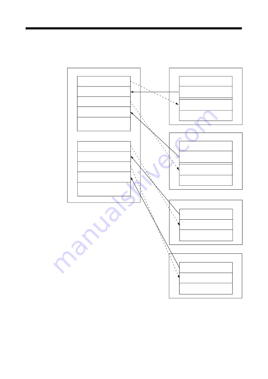
1)   PLC CPU (1 module) + Motion CPU (2 modules) 

The outline operation and the automatic refresh setting are as follows. 
 

Command device for 
the Motion CPU No.2

 (768 points)

CPU No.1 (PLC CPU)

Data registers

CPU No.2 (Motion CPU)

M0

M768

M1824

M2592

M3648

M8191

Monitor device for 
the Motion CPU No.2

(1056 points)

Internal relays

M0

M2000

M3055

M3072

M3839
M3840

M8191

Monitor device

(1056 points)

Command device 

 (768 points)

Internal relays

Command device for 
the Motion CPU No.3

 (768 points)

Monitor device for 
the Motion CPU No.3

(1056 points)

Command device for 
the Motion CPU No.2

 (118 points)

D0

D118

D758

D876

D1516

D8191

Monitor device for 
the Motion CPU No.2

(640 points)

Command device for 
the Motion CPU No.3

 (118 points)

Monitor device for 
the Motion CPU No.3

(640 points)

CPU No.2 (Motion CPU)

Data registers

D0

D640

D758

D8191

Monitor device

(640 points)

Command device


 (118 points)

CPU No.3 (Motion CPU)

M0

M2000

M3055

M3072

M3839
M3840

M8191

Monitor device

(1056 points)

Command device 

 (768 points)

Internal relays

CPU No.3 (Motion CPU)

Data registers

D0

D640

D758

D8191

Monitor device

(640 points)

Command device


 (118 points)


Содержание Q172CPU

Страница 1: ...Q173CPU N Q172CPU N Motion Controller SV43 Programming Manual Q172CPU Q173CPU Q172CPUN Q173CPUN ...

Страница 2: ...TIONS classify the safety precautions into two categories DANGER and CAUTION DANGER CAUTION Indicates that incorrect handling may cause hazardous conditions resulting in death or severe injury Indicates that incorrect handling may cause hazardous conditions resulting in medium or slight personal injury or physical damage Depending on circumstances procedures indicated by CAUTION may also be linked...

Страница 3: ...s or damage Never operate the switches with wet hands as this may lead to electric shocks Do not damage apply excessive stress place heavy things on or sandwich the cables as this may lead to electric shocks Do not touch the Motion controller servo amplifier or servomotor terminal blocks while the power is ON as this may lead to electric shocks Do not touch the built in power supply built in groun...

Страница 4: ...d in the instruction manual for the servo amplifier etc always install the electromagnetic contactor Install the emergency stop circuit externally so that the operation can be stopped immediately and the power shut off Use the Motion controller servo amplifier servomotor and regenerative resistor with the combi nations listed in the instruction manual Other combinations may lead to fire or faults ...

Страница 5: ...tive resistor model and the system application The protective functions may not function if the settings are incorrect The regenerative resistor model and capacity parameters must be set to values that conform to the operation mode servo amplifier and servo power supply module The protective functions may not function if the settings are incorrect Set the mechanical brake output and dynamic brake ...

Страница 6: ...t stack products past the limit When transporting the Motion controller or servo amplifier never hold the connected wires or cables When transporting the servomotor never hold the cables shaft or detector When transporting the Motion controller or servo amplifier never hold the front case as it may fall off When transporting installing or removing the Motion controller or servo amplifier never hol...

Страница 7: ...ure According to each instruction manual 20 C to 65 C 4 F to 149 F Atmosphere Indoors where not subject to direct sunlight No corrosive gases flammable gases oil mist or dust must exist Altitude 1000m 3280 84ft or less above sea level Vibration According to each instruction manual When coupling with the synchronization encoder or servomotor shaft end do not apply impact such as by hitting with a h...

Страница 8: ...gnal output of brake signals etc Incorrect installation may lead to signals not being output when trouble occurs or the protective functions not functioning Do not connect or disconnect the connection cables between each unit the encoder cable or PLC expansion cable while the power is ON Servo amplifier VIN 24VDC Control output signal RA Securely tighten the cable connector fixing screws and fixin...

Страница 9: ...verters and other equipment Use the units with the following conditions Conditions Item Q61P A1 Q61P A2 Q62P Q63P Q64P 10 10 10 30 10 100 to 120VAC 15 200 to 240VAC 15 100 to 240VAC 15 24VDC 35 100 to 120VAC 15 10 200 to 240VAC 15 Input power 85 to 132VAC 170 to 264VAC 85 to 264VAC 15 6 to 31 2VDC 85 to 132VAC 170 to 264VAC Input frequency 50 60Hz 5 Tolerable momentary power failure 20ms or less 7...

Страница 10: ...ricity buildup Do not perform a megger test insulation resistance measurement during inspection When replacing the Motion controller or servo amplifier always set the new module settings correctly When the Motion controller or absolute value motor has been replaced carry out a home position return operation using one of the following methods otherwise position displacement could occur 1 After writ...

Страница 11: ...lectric power or submarine repeating applications please contact your nearest Mitsubishi sales representative Although this product was manufactured under conditions of strict quality control you are strongly advised to install safety devices to forestall serious accidents when it is used in facilities where a breakdown in the product is likely to cause a serious accident 10 General cautions CAUTI...

Страница 12: ...autions Warranty Model code change 1CT784 1XB784 etc Japanese Manual Number IB NA 0300064 This manual confers no industrial property rights or any rights of any other kind nor does it confer any patent licenses Mitsubishi Electric Corporation cannot be held responsible for any problems involving industrial property rights which may occur as a result of using the contents noted in this manual 2004 ...

Страница 13: ... System overall configuration 1 25 1 3 4 Software packages 1 27 1 3 5 Restrictions on motion systems 1 30 1 4 Multiple CPU System 1 31 1 4 1 Overview 1 31 1 4 2 Installation of PLC CPU and Motion CPU 1 32 1 4 3 Precautions for using Q series I O modules and intelligent function modules 1 33 1 4 4 Modules subject to installation restrictions 1 34 1 4 5 Processing time of the Multiple CPU system 1 3...

Страница 14: ...n from The PLC CPU to The Motion CPU S P CHGT PLC instruction S P CHGT 4 32 4 7 Write from The PLC CPU to The Motion CPU S P DDWR PLC instruction S P DDWR 4 35 4 8 Read from The Devices of The Motion CPU S P DDRD PLC instruction S P DDRD 4 39 5 POSITIONING DEDICATED SIGNALS 5 1 to 5 88 5 1 Internal Relays 5 2 5 1 1 Axis statuses 5 13 5 1 2 Axis command signals 5 25 5 1 3 Axis statuses 2 5 32 5 1 4...

Страница 15: ...g position droop 6 23 6 3 21 Torque control compensation factor 6 23 6 3 22 Speed differential compensation 6 23 6 3 23 Servo parameters of vector inverter FR V500 6 24 6 4 Parameter Block 6 25 6 4 1 Relationships between the speed limit value acceleration time deceleration time and rapid stop deceleration time 6 28 6 4 2 S curve ratio 6 30 6 4 3 Allowable error range for circular interpolation 6 ...

Страница 16: ...rt invalid 7 79 7 13 14 G24 Cancel cancel start 7 80 7 13 15 G25 High speed oscillation 7 83 7 13 16 G26 High speed oscillation stop 7 85 7 13 17 G28 Home position return 7 86 7 13 18 G30 Second home position return 7 88 7 13 19 G32 Skip 7 90 7 13 20 G43 Tool length offset 7 94 7 13 21 G44 Tool length offset 7 96 7 13 22 G49 Tool length offset cancel 7 98 7 13 23 G53 Mechanical coordinate system s...

Страница 17: ...24 Control program end CLEAR 7 167 7 16 25 Time to wait TIME 7 169 7 16 26 Block transfers BMOV 16 bit unit 7 170 7 16 27 Block transfer BDMOV 32 bit unit 7 172 7 16 28 Identical data block transfers FMOV 7 174 7 16 29 Write device data to shared CPU memory MULTW 7 176 7 16 30 Read device data from shared CPU memory of the other CPU MULTR 7 178 7 16 31 Write words data to intelligent function modu...

Страница 18: ...7 8 11 Single Block Operation 8 81 8 12 High Speed Reading of Specified Data 8 86 8 13 Control Program Stop Function from The PLC CPU 8 87 9 USER FILES 9 1 to 9 2 9 1 Projects 9 1 9 2 User File List 9 2 10 ROM OPERATION FUNCTION 10 1 to 10 10 10 1 About the ROM Operating Function 10 1 10 2 Specifications of LED Switch 10 3 10 3 ROM Operation Function Details 10 5 10 4 Operating Procedure of ROM wr...

Страница 19: ...elf diagnosis error APP 6 APPENDIX 2 Error Codes Stored Using The Motion CPU APP 7 APPENDIX 2 1 Motion program setting errors Stored in D9190 APP 9 APPENDIX 2 2 Minor errors APP 10 APPENDIX 2 3 Major errors APP 26 APPENDIX 2 4 Servo errors APP 30 APPENDIX 2 5 PC link communication errors APP 45 APPENDIX 3 Motion dedicated signal APP 46 APPENDIX 3 1 Internal relay M APP 46 APPENDIX 3 2 Data Registe...

Страница 20: ...PU N Q172CPU N Motion controller SV13 SV22 Programming Manual Motion SFC This manual explains the Multiple CPU system configuration performance specifications functions programming error codes and others of the Motion SFC Optional IB 0300042 1XB781 Q173CPU N Q172CPU N Motion controller SV13 SV22 Programming Manual REAL MODE This manual explains the servo parameters positioning instructions device ...

Страница 21: ... system with the QCPU Optional SH 080485ENG 13JR75 QCPU Q Mode QnACPU Programming Manual Common Instructions This manual explains how to use the sequence instructions basic instructions application instructions and micro computer program Optional SH 080039 13JF58 QCPU Q Mode QnACPU Programming Manual PID Control Instructions This manual explains the dedicated instructions used to exercise PID cont...

Страница 22: ... Abbreviation for CPU No n n 1 to 4 of the CPU module for the Multiple CPU system Programming software package General name for MT Developer and GX Developer Operating system software General name for SW RN SV Q SV43 Operating system software for machine tool peripheral use SW5RN SV43Q MT Developer Abbreviation for Integrated start up support software package MT Developer GX Developer Abbreviation...

Страница 23: ...f each software CAUTION When designing the system provide external protective and safety circuits to ensure safety in the event of trouble with the Motion controller There are electronic components which are susceptible to the effects of static electricity mounted on the printed circuit board When handling printed circuit boards with bare hands you must ground your body or the work bench Do not to...

Страница 24: ... used can be selected One or more PLC CPU is necessary with the Multiple CPU system Q00CPU 8k steps Q01CPU 14k steps Q02CPU Q02HCPU 28k steps Q06HCPU 60k steps Q12HCPU 124k steps Q25HCPU 252k steps c The device data of other CPU can be used as the device data of self CPU because the Multiple CPU automatic refresh may do automatically data giving and receiving between each CPU of the Multiple CPU s...

Страница 25: ...troller switable for the machine can be realized And it also can correspond with the function improvement of the software package a Conveyor assembly use SV13 Offer liner interpolation circular interpolation helical interpolation constant speed control speed control fixed pitch feed and etc by the dedicated servo instruction Ideal for use in conveyors and assembly machines b Automatic machinery us...

Страница 26: ...am is shown below a Motion program start request S P SVST using the PLC program of PLC CPU or Motion program control program start request S P SFCS b Automatic start setting of Motion program control program c Start by CALL GOSUB GOSUBE instruction using other Motion program 2 JOG operation by the axis command signal of Motion CPU 3 Manual pulse generator operation by the positioning dedicated dev...

Страница 27: ...est of the Motion program J1 Axis 1 Start axis No Point In the above it is explained the start of axis designation program There are following 2 types as the Motion program Control program Only control instruction can be used the travel instruction by G code can not be used It is started by the S P SFCS of PLC CPU automatic start with parameter or CALL GOSUB GOSUBE instruction of other control pro...

Страница 28: ...Note 1 Set and correct using a peripheral device Note 1 PTP positioning instruction by high speed feed speed Linear positioning of the specified axis is executed from the current position to the specified coordinate position by all axes fixed speed CP positioning instruction by the speed specified with F Linear interpolation is executed from the current position to the specified coordinate positio...

Страница 29: ...otion program No 100 Program No specified with the S P SFCS instruction Program control function instruction The flow of execute program is controlled by conditions Create and correct using a peripheral device Note 1 JOG operation by the JOG dedicated device control All axes servo ON command turns on Transfer the JOG operation speed to D640L and D642L 1 axis forward rotation command SET RST Progra...

Страница 30: ...ed servo amplifier Data required for the acceleration deceleration of the positioning control etc Data required for the home position return Data required for the JOG operation ON OFF pattern data required for the limit switch output function REMARK Note 1 The following peripheral devices started by the SW6RN GSV43P can be used The personal computer by which WindowsNTR 4 0 WindowsR 98 WindowsR 200...

Страница 31: ...s 2 manual pulse generator enable flag turn off Program end instruction Program ends Turn off the axis 1 and axis 2 manual pulse generator enable flag for safety not to continue the manual pulse generator operation at the manual pulse generator operation end Note Motion program No 100 Program No specified with the S P SFCS instruction All axes servo ON command turns on Wait until axis 1 and axis 2...

Страница 32: ... the connected servo amplifier Data required for the acceleration deceleration of the positioning control etc Data required for the home position return Data required for the JOG operation ON OFF pattern data required for the limit switch output function REMARK Note 1 The following peripheral devices started by the SW6RN GSV43P can be used The personal computer by which WindowsNTR 4 0 WindowsR 98 ...

Страница 33: ...trol value at the positioning control are set up to 16 parameter blocks They are set with the Motion program JOG operation data and home position return data and it is used to change easily the acceleration deceleration processing acceleration deceleration time and speed limit value at the positioning control Section 6 4 7 Limit switch output data Output device watch data ON section output enable ...

Страница 34: ...3 axes Control modes PTP Point to Point control Constant speed positioning High speed oscillation control Method PTP Select of absolute or incremental data method Constant speed control Both absolute and incremental data method can be used together Selectable for each axis Control unit Command unit Address setting range Travel value setting range mm 10 4 mm inch 10 5 inch 2147483648 to 2147483647 ...

Страница 35: ... connect 3 modules M code function M code output function provided M code completion wait function provided Limit switch output function Number of output points 32 points Watch data Motion control data Word device Skip function Provided Override ratio setting function Override ratio setting 0 to 100 Absolute position system Made compatible by setting battery to servo amplifier Possible to select t...

Страница 36: ...ion SIN COS TAN ASIN ACOS ATAN Functions Numerical function ABS SQR BIN LN EXP BCD RND FIX FUP INT FLT DFLT SFLT Start end CALL CLEAR Home position return CHGA Speed torque setting TL CHGV CHGT Motion control WAITON WAITOFF EXEON EXEOFF Jump repetition processing CALL GOSUB GOSUBE IF GOTO IF THEN ELSE END WHILE DO END Instructions Data operation BMOV BDMOV FMOV BSET BRST SET RST MULTW MULTR TO FRO...

Страница 37: ... Programming tool IBM PC AT PC9800 series IBM PC AT A30TU A31TU Peripheral devices I F USB RS 232 SSCNET RS 422 SSCNET Home position return function Proximity dog type 2 types Count type 3 types Data set type 2 types Dog cradle type Stopper type 2 types Limit switch combined type Home position return retry function provided Home position shift function provided Proximity dog type count type data s...

Страница 38: ...e CPU s The direct data exchange method which made a device memory 2 port memory Number of pulses per revolutions 1 to 2147483647 PLS 1 to 65535 PLS Fixed parameters Amount of pulses per revolutions In the case of the unit setup mm 0 0001 to 214748 3647 mm In the case of the unit setup mm 0 0001 to 6 5535 mm Magnification 1 time 10 times 100 times 1000 times PLC ready flag M2000 M2000 turn it on w...

Страница 39: ...Expression only in the Motion program is the same as D which specified the data register D It is for holding compatibility with Motion controller A series c The positioning dedicated devices in Q173CPU N Q172CPU N are the same level as them in A273UHCPU A173UHCPU However TT TC CT CC cannot be used Also the following contents are added changed 1 DNC status M4320 to M4323 2 Control program monitor d...

Страница 40: ...e Motion CPU A series turns on off by interlock of STOP RUN switch The control using a PLC CPU is possible in the parameter setting b Forced stop signal Although the emergency stop input is executed with the CPU module or PLC base unit of the terminal there is not this terminal input in Q173CPU N Q172CPU N and the forced stop signal is used as the same function The forced stop signal can set an op...

Страница 41: ...ote 1 When using the external battery be sure to set the Battery A6BAT MR BAT to the Dividing unit Q173DV Battery A6BAT MR BAT is optional Note 2 Q172EX cannot be used in SV43 MITSUBISHI SSCNET CN1 Q173CPU MITSUBISHI LITHIUM BATTERY SSCNET CN2 SSCNET CN3 SSCNET CN4 Dividing unit Q173DV Battery A6BAT MR BAT MITSUBISHI LITHIUM BATTERY Note 1 Q173DVCBL M SSCNET cable SSCNET cable for MR H BN MR J2HBU...

Страница 42: ...ction module of the Q series Extension cable QC B Q172HBCBL M B SSCNET cable for MR H BN Motion module Q172LX Q172EX Q173PX Battery A6BAT MR BAT Note1 When using the external battery be sure to use the SSCNET cable Q172J2BCBL M B Q172HBCBL M B and to set the Battery A6BAT MR BAT Also install the Battery A6BAT MR BAT in the Battery unit Q170BAT Battery A6BAT MR BAT is optional Note2 Q172EX cannot b...

Страница 43: ...2CPU N Personal computer Windows 98 2000 XP only USB cable R c SSCNET configuration Motion CPU module Q173CPU N Q172CPU N SSC I F communication cable Q170CDCBL M Q170BDCBL M SSC I F Card Board A30CD PCF A 0BD PCF A30CD PCF SSCNET CARD MITSUBISHI Personal computer Note For information about GPP functions of PLC CPU refer to the operating manual of PLC Also refer to the help of each software for inf...

Страница 44: ... M H Q170ENCCBL M Serial absolute synchronous encoder 2 module RLS Lower stroke limit STOP Stop signal DOG CHANGE Proximity dog Speed position switching I O module of the Q Series or Special function module Analogue input output QY SSC I F Communication cable Extension cable Power supply module Q6 B UP to 7 extensions Note 1 Q172EX cannot be used in SV43 Serial absolute synchronous encoder cannot ...

Страница 45: ...he ratings and characteristics of the parts other than Motion controller servo amplifier and servomotor used in a system must be compatible with the Motion controller servo amplifier and servomotor Set the parameter values to those that are compatible with the Motion controller servo amplifier servomotor and regenerative resistor model and the system application The protective functions may not fu...

Страница 46: ...CPU base unit Serial absolute synchronous encoder cable MR JHSCBL M H Q170ENCCBL M Serial absolute synchronous encoder 2 module RLS Lower stroke limit STOP Stop signal DOG CHANGE Proximity dog Speed position switching I O module of the Q Series or Special function module Analogue input output QY SSC I F Communication cable Extension cable Power supply module Q6 B UP to 7 extensions Q172LX Q172PX Q...

Страница 47: ...he ratings and characteristics of the parts other than Motion controller servo amplifier and servomotor used in a system must be compatible with the Motion controller servo amplifier and servomotor Set the parameter values to those that are compatible with the Motion controller servo amplifier servomotor and regenerative resistor model and the system application The protective functions may not fu...

Страница 48: ...stallation manual SW6RNC GSVPROE A30CD PCF SSC I F card PCMCIA TYPE II 1CH card MT Developer SW6RNC GSVSETE Q170CDCBL3M A30CD PCF cable 3m 9 84ft Note Operating environment of the MT Developer is WindowsNT R 4 0 Windows R 98 Windows R 2000 Windows R XP English version only 2 Operating environment of the personal computer Operating environment is as follows IBM PC AT with which WindowsNT 98 2000 XP...

Страница 49: ... the operation of this software refer to the manual of Windows or guide book from the other supplier 2 The screen might not be correctly displayed depending on the system font size of WindowsNT R 4 0 Windows R 98 Windows R 2000 Windows R XP Be sure to use the small size fonts 3 Operating system type version a Confirmation method in the operating system 1 OS software TYPE 2 Software version 1 3 OS ...

Страница 50: ...on Operating system software version Programming software version Q173CPU Q173CPUN Q172CPU Q172CPUN Section No ROM operation B C M N Chapter 10 ROM operation For additional parameter Home position return parameter etc B C T M U M Vector inverter connectable B B Basic model QCPU Function version B Q00CPU Q01CPU B Home position return functions added D B Section 8 5 There is no restriction by the ve...

Страница 51: ... cable which connects the Motion CPU and servo amplifier which connects the Motion CPU are pulled from the bottom part of unit Make sure to secure sufficient space for pulling out the cable when designing the control panel 8 Motion CPU module is one module element of Q series Multiple CPU system It must be set the parameters of Q series Multiple CPU system for each PLC CPU Motion CPU module must a...

Страница 52: ...system configuration can be realized b You can increase the number of control axes by using a multiple Motion CPUs It is possible to control up to 96 axes by using three Q173CPU N s c You can reduce the PLC scan time of the overall system by using a multiple PLC CPUs and distributing the PLC control load among them 3 Communication among the CPUs in the Multiple CPU system a Transmission of data am...

Страница 53: ... of one or more PLC CPUs PLC CPU cannot be installed to the right of a Motion CPU 1 When the high performance model PLC CPU is used Power supply PLC CPU CPU 0 1 2 CPU 0 1 2 CPU 0 1 2 CPU 0 1 2 CPU 0 1 2 Motion CPU Installation positions of PLC CPUs Motion CPUs Number of CPUs 2 3 4 CPU 0 1 2 I O etc I O etc Motion CPU PLC CPU Power supply PLC CPU I O etc Motion CPU PLC CPU Power supply PLC CPU PLC ...

Страница 54: ... the Multiple CPU system These modules cannot be controlled by the PLC CPU so be sure to use the Motion CPU as a control CPU 3 Access range from a non control CPU a The Motion CPU can access only the modules controlled by the self CPU It cannot access the modules controlled by other CPUs b Access range from a non control CPU for the modules controlled by the Motion CPU are shown below I O setting ...

Страница 55: ... output module Q6 DA Total 256 points 2 Modules controlled by a Motion CPU cannot be installed in the extension base unit QA1S6 B Install them in the CPU base unit Q3 B or extension base unit Q6 B 3 A total of eight base units including one CPU base unit and seven extension base units can be used However the usable slots number of modules are limited to 64 per system including vacant slots If a mo...

Страница 56: ...n the following conditions When a total of 4 PLC CPUs Motion CPUs are used in the Multiple CPU system When the extension base units are used When the intelligent function modules handling large volumes of data are installed in the extension base unit When a total of 4 CPUs are used and the 4 CPUs have simultaneously accessed a module installed in an extension base unit When there are many automati...

Страница 57: ...Q173 CPU N These CPUs must not be reset If one of them is reset all CPU in the Multiple CPU system generate a MULTI CPU DOWN error CPU No 2 CPU No 3 CPU No 4 POINT 1 In a Multiple CPU system the PLC CPUs Motion CPUs of CPU No 2 3 or 4 cannot be reset individually When a PLC CPU or Motion CPU of CPU No 2 3 or 4 is reset while the Multiple CPU system is operating the other CPUs generate a MULTI CPU ...

Страница 58: ...ic function of GX Developer 2 Remove the cause of the error 3 Reset the PLC CPU of CPU No 1 or restart the power Resetting the PLC CPU of CPU No 1 or restarting the power resets all CPUs in the Multiple CPU system and the system is recovered 2 When CPU No 2 to 4 generated a CPU DOWN error If the PLC CPU Q173CPU N or Q172CPU N of CPU No 2 to 4 generated a CPU DOWN error the entire system may or may...

Страница 59: ... 1 When a CPU DOWN error occurs the CPU detecting the error will generate a MULTI CPU DOWN error Therefore the system may enter a MULTI CPU DOWN mode after detecting the CPU DOWN error in the CPU generating a MULTI CPU DOWN error instead of the error in the CPU that generated the CPU DOWN error in the first place In this case the common error data area may store a CPU number different from one cor...

Страница 60: ...ot operate from the beginning does not run All actual output PY points turn OFF No effect on other CPUs WDT error Varies depending on the error Self diagnosis error Stops at a CPU DOWN error All actual output PY points turn OFF Other CPUs may also stop depending on the parameter setting Operation disable errors Other CPU DOWN error Operation corresponding to STOP M2000 OFF Depends on the Operation...

Страница 61: ...rol Operation at STOP to RUN M2000 is turned on with switch STOP to RUN M2000 turns ON by switching STOP to RUN 1 set in setting register M2000 is turned on with switch STOP to RUN Set the condition in which the PLC ready flag M2000 turns on Forced stop Note None X PX 0 to 1FFF M 0 to 8191 None Set the bit device used for forced stop Basic system setting Latch range M 0 to 8191 B 0 to 1FFF F 0 to ...

Страница 62: ...ems in System Settings related to the entire Multiple CPU system must be identical to the parameter settings in the PLC CPU Power supply Parameter write Individual parameter Common system parameters Qn H CPU Qn H CPU Q173 CPU N Q172 CPU N PLC CPU parameters Motion CPU parameters PLC CPU parameters Motion CPU parameters Common system parameters Common system parameters Common system parameters Indi...

Страница 63: ...ters of the other CPUs via Multiple CPU parameter utilization in GX Developer Since Motion CPUs do not have this function however the common parameters must be set for each Motion CPU Type of parameter Name in Motion CPU Name in PLC CPU Verification item Remark Number of Multiple CPUs Number of CPU modules Operation mode Operation mode when a CPU stop error occurred Multiple CPU settings Automatic...

Страница 64: ...tting in GX Developer Number of CPU modules Operation mode when a CPU stop error occurred Number of automatic refresh points Settings 1 to 4 must be the same for all CPUs Number of CPU modules Error operation made at the stop of CPU Number of automatic refresh points Multiple CPU Settings Motion CPU setting in SW6RN GSV43P Multiple PLC Setting PLC CPU setting in GX Developer ...

Страница 65: ...t Settings Motion CPU setting in SW6RN GSV43P In GX Developer set the slot for Motion CPU control as the CPU number of the Motion CPU in I O Assignment Settings PLC CPU setting Control CPU No I O Assignment Setting PLC CPU setting in GX Developer Motion Slot Setting Motion CPU setting in SW6RN GSV43P ...

Страница 66: ... I O Assignment Settings PLC CPU setting in GX Developer In GX Developer the detailed settings may be omitted by setting the base mode Automatic Total number of bases and number of slots in each base I O Assignment Settings PLC CPU setting in GX Developer Base Settings Motion CPU setting in SW6RN GSV43P Note Only the Motion CPU may be set without setting the PLC CPU ...

Страница 67: ...points 10 slots for connection with GOT then set 10 slots as number of extension bases for connection with GOT in the system setting base setting Example When the 2nd stage of extension base is set as connection with GOT Set 10 slot as 2nd stage of extension base in the base setting If the bus connection with GOT is executed without above settings in the base setting of system setting SP UNIT LAY ...

Страница 68: ... exceeded the operation cycle the operation cycle over flag M2054 turns ON Even when Automatic setting is selected the duration of motion operation may exceed the operation cycle depending on the control conditions The actual duration of motion operation unit μs is stored in the D9188 and the current setting of operation cycle unit μs is stored in the D9197 Monitor these special registers and adju...

Страница 69: ...ge from 0 to 1 in the lowest bit in the D704 Condition in which the M2000 turns from ON to OFF With the RUN STOP switch set to the RUN side set 0 in the setting register for PLC ready flag D704 The Motion CPU detects a change from 1 to 0 in the lowest bit in the D704 Change the RUN STOP switch from the RUN side to the STOP side c Forced stop input setting Specify the bit device used for executing ...

Страница 70: ...arentheses 1 5 10 20 70 ms 0 1 0 2 0 4 0 6 1 ms 10ms 0 2ms First I O No 00 to FF0 in units of 16 points 0 QY Output module Number of I O points 0 16 32 64 128 256 16 First I O No 00 to FF0 in units of 16 points 0 Number of I O points 0 16 32 64 128 256 16 Input response time setting 1 5 10 20 70 ms 10ms QH QX Y Input output composite module High speed read setting Used Unused Unused First I O No 0...

Страница 71: ... PARAMETER ERROR 3012 The reference CPU No set in the parameter differ from the setting in a Multiple CPU system PARAMETER ERROR 3013 Multiple CPU automatic refresh setting in any of the followings in a Multiple CPU system When a bit device is set as a refreshed a number except for a multiple of 16 is set as the refresh first device A non specifiable device is specified The number of transmitting ...

Страница 72: ...U 1 0H position of I O No a In the Multiple CPU system the slots corresponding to the number of units set by a multiple CPU parameter are occupied by the PLC CPU Motion CPU b I O modules and intelligent function modules are installed in slots available to the right of those occupied by the PLC CPU Motion CPU c I O No of the control module may be assigned independently for each CPU in the Motion CP...

Страница 73: ...ules controlled by CPU No 1 3 Setting of the Motion CPU control modules by the PLC CPU Follow the table below when the Motion CPU control modules are set in I O Assignment Settings of the PLC CPU The PLC CPU handles the Q172LX and Q173PX as intelligent function modules having 32 occupied points Type and number of points may be left unset Module name Type Number of points Remarks Input module Input...

Страница 74: ... QCPU slot Slot 0 Slot 1 Slot 2 Head I O number 3E00H 3E10H 3E20H 3E30H The I O No of the PLC CPU Motion CPU are used in the following cases When writing data to the shared CPU memory of the self CPU using the S TO instruction When reading data from the shared CPU memory of the other CPU using the FROM instruction When reading data from the shared CPU memory of the other CPU using an intelligent f...

Страница 75: ...V43P for the detailed operating procedure on the system settings screen 1 Double click the slot position display the Motion Slot Settings dialog box 2 Select the I O module 4 Select applicable module type and number of points for the I O module to be used 3 Click Detail Setting 5 Set the first I O No PX No PY No 6 Click OK System Settings Motion Slot Settings I O Module Settings POINT I O No s can...

Страница 76: ...strictions of module install GX developer start Start the GX Developer Ver 6 or later Refer to the GX Developer manual for GX Developer start Parameters etc create Create the parameter setting such as Multiple CPU setting and control CPU setting and the PLC programs Create the parameters for CPU No 1 to 4 and PLC programs Refer to the QCPU User s Manual Function Explanation Program Fundamentals fo...

Страница 77: ...osition Release PLC CPU CPU No 1 reset Set the RUN STOP switch for each CPU CPU No 1 to 4 to RUN position PLC CPU Check of state for all CPUs Check whether all CPUs in the Multiple CPU system become RUN state error by reset release of the PLC CPU CPU No 1 PLC CPU Motion CPU Check and correct the error details Each CPU debug If an error has occurred check and correct the error details using the PC ...

Страница 78: ...sed the data in the device memory of the other CPU is read automatically so the device data of other CPU can be used as the device data of self CPU The diagram below illustrates the automatic refresh operation involving 32 points B0 to B1F for the PLC CPU of CPU No 1 and 32 points B20 to B3F for the Motion CPU of CPU No 2 Self CPU operation data area System area Automatic refresh area CPU No 1 PLC...

Страница 79: ... DOWN error will occur in the PLC CPU or the Motion CPU the automatic refresh function is not executed When one CPU generated a CPU DOWN error the other CPU free from CPU DOWN error retains the data saved immediately before the CPU DOWN error occurred For example if CPU No 2 generated a CPU DOWN error while B20 was ON in the operation block diagram in a B0 of CPU No 1 remains ON If necessary inter...

Страница 80: ... may be refreshed using word device setting 2 The number of points in the shared CPU memory set in units of 2 points 2 words is set in the send range for each CPU 2 points if word device is specified for the CPU side device or 32 points if bit device is specified Data of the CPUs for which 0 is set as the number of points representing the send range of the CPU will not be refreshed Assume that 32 ...

Страница 81: ...ng 1 Send range for CPU No 1 Last address of CPU side device Last address of the shared CPU memory for each CPU 5 Set the same number of transmitting points for all CPUs in the Multiple CPU system If any of the CPUs has a different number of transmitting points a PARAMETER ERROR will be occurred c CPU side device The following devices can be used for automatic refresh Other devices cannot be set i...

Страница 82: ...ng 1 Link relay Setting 2 Link register Settings 1 to 4 may use different devices Setting 3 Link relay The same device may be used for settings 1 to 4 In setting 1 shown to the left 160 points from B0 to B9F are used Therefore setting 3 can use device No after BA0 Device numbers may not overlap even partially such as specifying B0 to B9F in setting 1 and B90 to B10F in setting 3 The first and last...

Страница 83: ...y for each CPU For example you may set link relay for CPU No 1 and internal relay for CPU No 2 Set the same number of points for all CPUs When the CPU side device for CPU No 1 is the same as that for CPU No 2 When the CPU side device for CPU No 1 is different from that for CPU No 2 Refresh settings of CPU No 2 Refresh settings of CPU No 1 ...

Страница 84: ... c e s s i n g W r i t e d u r i n g E N D p r o c e s s i n g Maximum 8k words CPU No 2 receiving data No 2 CPU No 3 receiving data No 2 CPU No 4 receiving data No 2 CPU No 1 transmitting data No 2 CPU No 2 receiving data No 3 CPU No 3 receiving data No 3 CPU No 4 receiving data No 3 CPU No 1 transmitting data No 3 CPU No 2 receiving data No 4 CPU No 3 receiving data No 4 CPU No 4 receiving data ...

Страница 85: ...anation Program Fundamentals about the setting for the PLC CPU The first device can be arbitrarily set up for every CPU DUMMY can be set to the first device except the self CPU The motion device can be set as a first device b Setting selection send range refresh range for each CPU 1 The refresh setting of four ranges can be set by setting selection For example ON OFF data may be refreshed using bi...

Страница 86: ...t be set to the self CPU DUMMY setting should set as the first devise column B The self CPU does not execute the automatic refresh to the other CPU which carried out DUMMY setting B A white portion can be set A 6 Set the same number of transmitting points for all CPUs in the Multiple CPU system If any of the CPUs has a different number of transmitting points a PARAMETER ERROR will be occurred ...

Страница 87: ...sister W Motion resister None Link relay B Internal relay M Output Y Specify 0 or a multiple of 16 as the first No One transmitting point occupies 16 points If the device No does not overlap it is right The device of CPU No 4 at setting 1 is not refreshed by the CPU No 2 If the device No does not overlap it is right The device of CPU No 4 at setting 2 is not refreshed by the CPU No 2 Self CPU CPU ...

Страница 88: ...e can also be shortened Example of the automatic refresh setting using the Dummy setting is as follows Example Motion CPU No 3 This part is not refreshed so that a dummy setting Motion CPU No 4 PLC CPU No 1 Motion CPU No 2 Read data of CPU No 3 Read data of CPU No 3 PLC CPU CPU No 1 Automatic refresh setting 1 Motion CPU CPU No 3 Automatic refresh setting 1 Motion CPU CPU No 2 Automatic refresh se...

Страница 89: ...n device Common signal 54 points M2400 D758 to Axis status 20 points 32 axes to Common device Monitor 42 points M3040 D800 to Unusable 32 points to Axis monitor device 2 20 points 32 axes M3072 D1440 to Common device Command signal 64 points to Control program monitor device 6 points 16 programs M3136 D1536 to Special relay allocated device Command signal 64 points to Control change register 2 Ove...

Страница 90: ...on CPU Internal relays Monitor device 1056 points Command device 768 points Monitor device 320 points Command device 320 points Data registers Command device 118 points Monitor device 640 points Command device 96 points Monitor device 778 points Automatic refresh setting 1 PLC CPU CPU No 1 Motion CPU CPU No 2 Send range for each CPU CPU side device Send range for each CPU CPU side device CPU share...

Страница 91: ...144 M2463 No 2 20 M4000 M4319 No 3 No 3 No 4 No 4 Automatic refresh setting 4 PLC CPU CPU No 1 Motion CPU CPU No 2 Send range for each CPU CPU side device Send range for each CPU CPU side device CPU share memory G Dev starting D0 CPU share memory G Dev starting CPU Point Start End Start End CPU Point Start End Start End No 1 96 D758 D853 No 1 96 D1536 D1631 No 2 778 D854 D1631 No 2 778 D758 D1535 ...

Страница 92: ...ts Internal relays Command device for the Motion CPU No 3 768 points Monitor device for the Motion CPU No 3 1056 points Command device for the Motion CPU No 2 118 points D0 D118 D758 D876 D1516 D8191 Monitor device for the Motion CPU No 2 640 points Command device for the Motion CPU No 3 118 points Monitor device for the Motion CPU No 3 640 points CPU No 2 Motion CPU Data registers D0 D640 D758 D8...

Страница 93: ... 2 640 D118 D757 No 2 640 D0 D639 No 3 0 No 3 0 No 4 No 4 Automatic refresh setting 3 PLC CPU CPU No 1 Motion CPU CPU No 2 Send range for each CPU CPU side device Send range for each CPU CPU side device CPU share memory G Dev Starting M1824 CPU share memory G Dev starting CPU Point Start End Start End CPU Point Start End Start End No 1 48 M1824 M2591 No 1 48 No 2 0 No 2 0 No 3 66 M2592 M3647 No 3 ...

Страница 94: ...ge for each CPU CPU side device CPU share memory G Dev starting CPU Point Start End Start End No 1 118 No 2 640 No 3 0 No 4 Note A dummy setting is made so that an excessive device may not be refreshed in the Motion CPU No 2 Automatic refresh setting 3 Motion CPU CPU No 3 Send range for each CPU CPU side device CPU share memory G Dev starting CPU Point Start End Start End No 1 48 M3072 M3839 No 2 ...

Страница 95: ...CPU IN THE MULTIPLE CPU SYSTEM POINT In the case of the combination PLC CPU 1 module Motion CPU 3 modules with SV43 make all the devices of all the CPUs refresh as mentioned above because the setting that Read Write is made of the PLC CPU can not be executed ...

Страница 96: ... the automatic refresh area and the area after 812H becomes the user defined area The diagram below shows the structure of shared CPU memory and accessibility from a PLC program Self CPU operation data area System area Automatic refresh area User defined area Shared CPU memory 0H 1FFH to 200H 7FFH to 800H FFFH to Self CPU Write Not allowed Allowed Read Write Read Not allowed Not allowed Not allowe...

Страница 97: ... stored D9014 7H to 1CH Not used Not used 1DH Switch status CPU switch status The switch status of the CPU is stored D9200 1EH LED status CPU LED status The bit pattern of the CPU LED is stored D9201 1FH CPU operation status CPU operation status The operation status of the CPU is stored D9015 Note Refer to the corresponding special register for details b The self CPU operation data area is refresh...

Страница 98: ...ing flag Axis17 to 32 The speed changing flag is stored by the 1 to 32 axis each bit As for a bit s actually being set Q173CPU N J1 to J32 Q172CPU N J1 to J8 OFF Start accept usable ON Start accept disable 206H 518 address 207H 519 address J2 J1 b1 b0 b15 J16 J32 J17 208H 520 Synchronous encoder current value changing flag Axis1 to 12 Unusable with SV43 The synchronous encoder current value change...

Страница 99: ... User defined area This area is used for the communication among each CPU in the Multiple CPU system using FROM S TO instructions and the intelligent function module devices of the PLC CPU Among each CPU communicates using MULTR instruction or MULTW instruction of the operating control program in the Motion CPU Refer to the section 7 16 29 to 7 16 30 for MULTR instruction or MULTW instruction Afte...

Страница 100: ...PU Note As for the details of each instruction it explains after the next section 4 1 1 Restriction item of the Motion dedicated PLC instruction 1 To self CPU high speed interrupt accept flag from CPUn Common precautions of the Motion dedicated PLC instruction as shown below a To self CPU high speed interrupt accept flag from CPUn is shown in the following table To self CPU high speed interrupt ac...

Страница 101: ... speed interrupt accept flag from CPUn 2 Execution of the Motion dedicated PLC instruction a Motion dedicated PLC instruction can be executed with fixed cycle execute type PLC and interrupt PLC However as for a complete device the program turned on according to fixed cycle executed type PLC and program type scan or low speed executed interrupt PLC is different b One Motion CPU can be accepted up t...

Страница 102: ...C CPU returns the OPERATION ERROR 4107 f When multiple Motion dedicated PLC instructions are directly executed because one contact point turns on an instruction may not be executed In this case create a program with reference to program example Program example 2 Program example 1 Program which executes multiple instructions to the same shaft of the Motion CPU of same CPU No SP CHGA K0 M3 D2 H3E1 R...

Страница 103: ... SET M21 SET M25 SET M27 RST M1001 Program example 2 To self CPU high speed interrupt accept flag from CPU1 U3E1 G48 0 Start accept flag of the Axis 1 CPU No 2 U3E1 G516 0 Start accept flag of the Axis 2 CPU No 2 U3E1 G516 1 To self CPU high speed interrupt accept flag from CPU1 U3E1 G48 0 Start accept flag of the Axis 4 CPU No 2 U3E1 G516 3 To self CPU high speed interrupt accept flag from CPU1 U...

Страница 104: ...the Motion dedicated PLC instruction is frequently performed from the PLC CPU the scan time of the PLC CPU is not only prolonged but delay will arise in the communication processing of the Motion CPU Perform execution of the Motion dedicated PLC instruction from the PLC CPU by S P DDWR S P DDRD S P CHGV instruction etc only at the time of necessity ...

Страница 105: ...etting by motion register 20000 to 28191 4C04 Axis No set by SVST instruction is injustice 4C05 Axis No set by CHGA instruction is injustice 4C06 Axis No set by CHGV instruction is injustice 4C07 Axis No set by CHGT instruction is injustice 4C08 When using the S P SFCS S P SVST S P CHGA instruction There are 33 or more instruction requests to the Motion CPU from the PLC CPU in S P SFCS S P SVST S ...

Страница 106: ...1 To self CPU high speed interrupt accept flag from CPUn accept disable 5 System area used by Motion dedicated instruction 204H to 20DH The complete status of the each flag is stored in the following address Shared CPU memory address Name Description 204H 516 Start accept flag Axis1 to 16 205H 517 Start accept flag Axis17 to 32 The start accept flag is stored by the 1 to 32 axis each bit As for a ...

Страница 107: ...qualification possible Start request S SFCS n1 SP SFCS n1 SP SFCS S SFCS n2 D1 D2 n2 D1 D2 Instruction Condition Start request Setting data Setting data Description Data type n1 First I O No of the target CPU 16 Value to specify actually is the following Note 1 CPU No 2 3E1H CPU No 3 3E2H CPU No 4 3E3H 16 bit binary n2 Motion program Control program No to start 16 bit binary D1 Complete devices D1...

Страница 108: ... Indirect setting by motion register n2 20000 The control program No stored in the motion register Motion CPU side is started n2 20000 1 The sequence No stored in the motion register Motion CPU side is started n2 usable range 20000 to 28191 Description 1 This instruction is dedicated instruction toward the Motion CPU in the Multiple CPU system Errors occurs when it was executed toward the CPU exce...

Страница 109: ...Un State display device D1 1 at the instruction start accept completion t ON ON S P SFCS instruction OFF ON OFF OFF OFF 1 scan PLC program Instruction accept completion at the Motion CPU side END END END END Motion program Control program Instruction start accept complete device D1 0 S P SFCS execution Motion program execution ON Abnormal completion only ...

Страница 110: ... instruction requests to the Motion CPU from the PLC CPU in S P SFCS S P SVST and S P CHGA sum table simultaneously and the Motion CPU cannot process them 4C09 CPU No of the instruction cause is injustice Confirm a program and correct it to a correct PLC program Note 0000H Normal The error flag SM0 is turned on an operation error in the case shown below and an error code is stored in SD0 Error cod...

Страница 111: ...e program M1 M0 X0 SP SFCS K11000 M0 D0 H3E3 Normal complete program M1 Abnormal complete program M1 Set the data in the data register of No specified with SFCS instruction 10000 Motion program Motion CPU side O0010 D1000 30 Motion program No D1001 200 Sequence No PLC program PLC CPU side 2 This program starts the Motion program Control program No 30 and sequence No 200 of the Motion CPU No 4 by i...

Страница 112: ...n Condition Start request Setting data Setting data Description Data type n1 First I O No of the target CPU 16 Value to specify actually is the following Note 1 CPU No 2 3E1H CPU No 3 3E2H CPU No 4 3E3H 16 bit binary S1 Axis No Jn Note 2 to start Q173CPU N J1 to J32 Q172CPU N J1 to J8 Character sequence S2 Motion program Axis designation program No to start 16 bit binary D1 Complete devices D1 0 D...

Страница 113: ...accept flag from CPUn 4 It is necessary to take an inter lock by the start accept flag of the shared CPU memory so that multiple instructions may not be executed toward the same axis of the same Motion CPU No Operation State display device D1 1 at the instruction start accept completion t ON ON S P SVST instruction OFF ON OFF OFF OFF 1 scan PLC program Instruction accept completion at the Motion C...

Страница 114: ...essing Setting range 1 Setting of the starting axis The starting axis set as S1 sets J Axis No in a character sequence S1 usable range Q173CPU N 1 to 32 Q172CPU N 1 to 8 Up to 8 axes can be set If multiple axes are set it sets without dividing in a space etc The axis No set in the system setting Refer to Section 6 1 is used as the axis No to start And the axis No to start does not need to be a ord...

Страница 115: ...tion program No stored in the motion register Motion CPU side is started S2 20000 1 The sequence No stored in the motion register Motion CPU side is started S2 20000 2 The parameter block No stored in the motion register Motion CPU side is started S2 usable range 20000 to 28191 Start accept flag System area The complete status of the start accept flag is stored in the address of the start accept f...

Страница 116: ...truction is injustice 4C08 There are 33 or more instruction requests to the Motion CPU from the PLC CPU in S P SFCS S P SVST and S P CHGA sum table simultaneously and the Motion CPU cannot process them 4C09 CPU No of the instruction cause is injustice Confirm a program and correct it to a correct PLC program Note 0000H Normal The error flag SM0 is turned on an operation error in the case shown bel...

Страница 117: ... M0 D0 H3E3 RST M100 M100 J1J2 M0 Normal complete program M1 Abnormal complete program M1 To self CPU high speed interrupt accept flag from CPU U3E3 G48 0 Start accept flag of the axis No 1 CPU No 4 U3E3 G516 0 Start accept flag of the axis No 2 CPU No 4 U3E3 G516 1 Set the data in the data register of No specified with SVST instruction 10000 Motion program Motion CPU side O0015 D2000 20 Motion pr...

Страница 118: ...data Setting data Description Data type n1 First I O No of the target CPU 16 Value to specify actually is the following Note 1 CPU No 2 3E1H CPU No 3 3E2H CPU No 4 3E3H 16 bit binary S1 Axis No Jn Note 2 to execute the home position return Q173CPU N J1 to J32 Q172CPU N J1 to J8 Character sequence S2 Dummy Set the any of constant etc 32 bit binary D1 Complete devices D1 0 Device which make turn on ...

Страница 119: ...executed toward the same axis of the same Motion CPU No Operation State display device D1 1 at the instruction start accept completion t ON ON S P CHGA instruction OFF ON OFF OFF OFF 1 scan PLC program Instruction accept completion at the Motion CPU side END END END END Home position return Instruction start accept complete device D1 0 Start accept flag axis OFF ON To self CPU high speed interrupt...

Страница 120: ...le range Q173CPU N 1 to 32 Q172CPU N 1 to 8 The number of axes which can set are only 1 axis The axis No set in the system setting Refer to Section 6 1 is used as the axis No to start Start accept flag System area The complete status of the start accept flag is stored in the address of the start accept flag in the shared CPU memory Shared CPU memory address is decimal address Description 204H 516 ...

Страница 121: ...S P SFCS S P SVST and S P CHGA sum table simultaneously and the Motion CPU cannot process them 4C09 CPU No of the instruction cause is injustice Confirm a program and correct it to a correct PLC program Note 0000H Normal The error flag SM0 is turned on an operation error in the case shown below and an error code is stored in SD0 Error code Note Error factor Corrective action 2110 The CPU No to be ...

Страница 122: ...self CPU high speed interrupt accept flag from CPU U3E3 G48 0 J1 M0 Normal complete program M1 Abnormal complete program M1 Start accept flag of the axis No 1 CPU No 4 U3E3 G516 0 Program which execute the home position return of the axis No 1 of the Motion CPU CPU No 4 from PLC CPU CPU No 1 dummy ...

Страница 123: ...ption Data type n1 First I O No of the target CPU 16 Value to specify actually is the following Note 1 CPU No 2 3E1H CPU No 3 3E2H CPU No 4 3E3H 16 bit binary S1 Axis No Jn Note 2 to execute the speed change Q173CPU N J1 to J32 Q172CPU N J1 to J8 Character sequence S2 Setting of the current value to change 32 bit binary D1 Complete devices D1 0 Device which make turn on for one scan at start accep...

Страница 124: ...ously It is necessary to take an inter lock by the to self CPU high speed interrupt accept flag from CPUn 4 It is necessary to take an inter lock by the speed changing flag of the shared CPU memory so that multiple instructions may not be executed toward the same axis of the same Motion CPU No Operation State display device D1 1 at the instruction start accept completion t ON ON S P CHGV instructi...

Страница 125: ... to change mm 6000000 to 6000000 10 2 mm min inch 6000000 to 6000000 10 3 inch min degree 2147483648 to 2147483647 10 3 degree min Speed changing flag System area The complete status of the start accept flag is stored in the address of the start accept flag in the shared CPU memory Shared CPU memory address is decimal address Description 206H 518 207H 519 The start accept flag is stored by the 1 t...

Страница 126: ...code Note Error factor Corrective action 2110 The CPU No to be set by First I O NO of the target CPU 16 is specified 2114 The self CPU by First I O No of the target CPU 16 is specified 2117 The CPU except the Motion CPU by First I O No of the target CPU 16 is specified 4004 The instruction is composed of devices except usable devices 4100 Since 0 to 3DFH 3E4H by First I O No of the target CPU 16 i...

Страница 127: ...8 Proximity dog count data set dog cradle stopper and limit switch combined type home position return Speed change cannot be made Minor error Error code 301 Note occurs JOG operation Speed change to negative speed is not made Speed is controlled at speed limit value Minor error Error code 305 Note occurs Note Minor error Error code 301 Speed change was made during home position return Minor error ...

Страница 128: ... of CHGV Positioning completion M2401 20n OFF In position M2402 20n ON Command in position M2403 20n OFF Speed change 0 accepting flag M2240 n ON b When re starting make a speed change to positive speed c When positioning is end turn on the stop command d When a negative speed change is executed again after negative speed completion CHGV instruction is ignored 4 When the complete round is set in G...

Страница 129: ...mains ON during the standby in P1 Turn on the stop command to end the positioning at this point 3 A speed change to negative speed is ignored if it is made during stop by the waiting for FIN using the M code FIN signal waiting function in the constant speed control O10 G90 N1 G01 X10000 Y0 F1000 N2 Y10000 N3 X10000 M02 Stat request SVST Start accept M2001 n Speed change request CHGV Change speed C...

Страница 130: ...rogram example SP CHGV K1000 M0 D0 H3E3 RST M100 M100 To self CPU high speed interrupt accept flag from CPU U3E3 G48 0 J1 M0 Normal complete program M1 Abnormal complete program M1 Speed changing flag of the axis No 1 CPU No 4 U3E3 G518 0 Program which changes the positioning speed of the axis No 1 of the Motion CPU CPU No 4 from PLC CPU CPU No 1 to 1000 P1 P2 P3 X axis Y axis Start point ...

Страница 131: ...g data Setting data Description Data type n1 First I O No of the target CPU 16 Value to specify actually is the following Note 1 CPU No 2 3E1H CPU No 3 3E2H CPU No 4 3E3H 16 bit binary S1 Axis No Jn Note 2 to execute the torque limit value change Q173CPU N J1 to J32 Q172CPU N J1 to J8 Character sequence S2 Setting of the torque limit value change to change 16 bit binary D1 Complete devices D1 0 De...

Страница 132: ...m CPUn Operation State display device D1 1 at the instruction start accept completion t ON ON S P CHGT instruction OFF ON OFF OFF OFF 1 scan PLC program Instruction accept completion at the Motion CPU side END END END END Torque limit value change Instruction start accept complete device D1 0 To self CPU high speed interrupt accept flag from CPUn S P CHGT execution Torque limit value change proces...

Страница 133: ...0 is turned on an operation error in the case shown below and an error code is stored in SD0 Error code Note Error factor Corrective action 2110 The CPU No to be set by First I O NO of the target CPU 16 is specified 2114 The self CPU by First I O No of the target CPU 16 is specified 2117 The CPU except the Motion CPU by First I O No of the target CPU 16 is specified 4004 The instruction is compose...

Страница 134: ...Set data Description Data type n1 First I O No of the target CPU 16 Value to specify actually is the following Note 1 CPU No 1 3E0H CPU No 2 3E1H CPU No 3 3E2H CPU No 4 3E3H 16 bit binary S1 First device of the self CPU in which control data is stored S2 First device of the self CPU in which writing data is stored D1 First device of the target Motion CPU which stores the writing data 16 bit binary...

Страница 135: ...ed by data in the shared CPU memory of the target CPU Motion CPU whether the instruction is acceptable or not When the Motion dedicated PLC instruction is started continuously it is must be design to execute next instruction after executing instruction complete device on 4 The target CPU device range check is not executed with self CPU at the S P DDWR instruction execution but it checks by the tar...

Страница 136: ...R instruction accept First S P DDWR instruction completion with response Second S P DDWR instruction completion with response ON Abnormal completion OFF Normal completion ON Abnormal completion OFF Normal completion Errors The abnormal completion in the case shown below and the error code is stored in the control data S1 0 Complete status Complete status Note Error code H Error factor Corrective a...

Страница 137: ...of the target CPU 16 is specified Number of the writing data is except 1 to 16 4101 Number of writing data exceeds range of the storage device of the written data Confirm a program and correct it to a correct PLC program Note 0000H Normal Program example M10 D51 X0 D50 SP DDWR D0 D100 M10 H3E1 SM400 K10 MOV M11 M11 M10 D51 X0 D50 SP DDWR D0 D100 M10 H3E1 SM400 K10 MOV M11 M11 M0 SET M10 M0 M10 M0 ...

Страница 138: ...ng data Set data Description Data type n1 First I O No of the target CPU 16 Value to specify actually is the following Note 1 CPU No 1 3E0H CPU No 2 3E1H CPU No 3 3E2H CPU No 4 3E3H S1 First device of the self CPU in which control data is stored S2 First device of the target CPU in which reading data is stored D1 First device of the self CPU which stores the reading data 16 bit binary D2 Bit devic...

Страница 139: ...d by data in the shared CPU memory of the target CPU Motion CPU whether the instruction is acceptable or not When the Motion dedicated PLC instruction is started continuously it is must be design to execute next instruction after executing instruction complete device on 4 The target CPU device range check is not executed with self CPU at the S P DDRD instruction execution but it checks by the targ...

Страница 140: ...D instruction accept First S P DDRD instruction completion with response Second S P DDRD instruction completion with response ON Abnormal completion OFF Normal completion ON Abnormal completion OFF Normal completion Errors The abnormal completion in the case shown below and the error code is stored in the control data S1 0 Complete status Complete status Note Error code H Error factor Corrective a...

Страница 141: ... I O No of the target CPU 16 is specified Number of the writing data is except 1 to 16 4101 Number of writing data exceeds range of the storage device of the written data Confirm a program and correct it to a correct PLC program Note 0000H Normal Program example M0 D51 X0 D50 SP DDRD D0 D100 M0 H3E1 SM400 K10 MOV Normal complete processing M1 M1 M10 D51 X0 D50 SP DDRD D0 D100 M10 H3E1 SM400 K10 MO...

Страница 142: ...nal signals The external input signals to the Motion CPU are shown below Upper lower limit switch input The upper lower limit of the positioning range is controlled Stop signal This signal makes the starting axis stop Proximity dog signal ON OFF signal from the proximity dog Manual pulse generator input Signal from the manual pulse generator Configuration between modules Sensor solenoid etc DI O M...

Страница 143: ... 8 axes 5 1 Internal Relays 1 Internal relay list Device No Purpose Device No Purpose M0 M3840 to User device 2000 points to User device 160 points M2000 M4000 to Common device Status 320 points to Axis I O signal Axis status 2 10 points 32 axes M2320 M4320 to Special relay allocated device Status 80 points to Unusable 80 points M2400 M4400 to Axis status 20 points 32 axes to Axis I O siganal Axis...

Страница 144: ...3 M2640 to M2659 9 Home position return request Main cycle 14 M2660 to M2679 10 Home position return complete Operation cycle 15 M2680 to M2699 11 FLS 16 M2700 to M2719 12 RLS 17 M2720 to M2739 13 STOP 18 M2740 to M2759 14 External signals DOG CHANGE Main cycle 19 M2760 to M2779 15 Servo ready 20 M2780 to M2799 16 Torque limiting Operation cycle Status signal 21 M2800 to M2819 17 22 M2820 to M2839...

Страница 145: ... 12 M3420 to M3439 8 Servo error reset command Main cycle 13 M3440 to M3459 14 M3460 to M3479 9 External stop input disable at start command At start Command signal 15 M3480 to M3499 10 16 M3500 to M3519 11 17 M3520 to M3539 12 18 M3540 to M3559 13 19 M3560 to M3579 14 Unusable 20 M3580 to M3599 21 M3600 to M3619 15 Servo OFF command Operation cycle Command signal 22 M3620 to M3639 16 23 M3640 to ...

Страница 146: ...19 8 Unusable 13 M4120 to M4129 9 Unusable note 1 14 M4130 to M4139 M4009 Single block processing signal 15 M4140 to M4149 16 M4150 to M4159 17 M4160 to M4169 18 M4170 to M4179 19 M4180 to M4189 20 M4190 to M4199 21 M4200 to M4209 22 M4210 to M4219 23 M4220 to M4229 24 M4230 to M4239 25 M4240 to M4249 26 M4250 to M4259 27 M4260 to M4269 28 M4270 to M4279 29 M4280 to M4289 30 M4290 to M4299 31 M430...

Страница 147: ... 8 13 M4520 to M4529 9 Unusable Note 1 14 M4530 to M4539 M4408 Single block mode signal 15 M4540 to M4549 M4409 Single block start signal 16 M4550 to M4559 M4418 Axis interlock valid invalid 17 M4560 to M4569 18 M4570 to M4579 19 M4580 to M4589 20 M4590 to M4599 21 M4600 to M4609 22 M4610 to M4619 23 M4620 to M4629 24 M4630 to M4639 25 M4640 to M4649 26 M4650 to M4659 27 M4660 to M4669 28 M4670 to...

Страница 148: ...M2028 Axis 28 M2083 Axis 23 M2029 Axis 29 M2084 Axis 24 M2030 Axis 30 M2085 Axis 25 M2031 Axis 31 M2086 Axis 26 M2032 Axis 32 Start accept flag Operation cycle Status signal Note 1 Note 2 M2087 Axis 27 M2033 Unusable M2088 Axis 28 M2089 Axis 29 M2034 Personal computer link communication error flag Operation cycle Status signal M2090 Axis 30 M2035 M2091 Axis 31 M2036 M2092 Axis 32 Speed changing fl...

Страница 149: ...99 M2139 Axis 12 M2200 M2140 Axis 13 M2201 M2141 Axis 14 M2202 M2142 Axis 15 M2203 M2143 Axis 16 M2204 M2144 Axis 17 M2205 M2145 Axis 18 M2206 M2146 Axis 19 M2207 M2147 Axis 20 M2208 M2148 Axis 21 M2209 M2149 Axis 22 M2210 M2150 Axis 23 M2211 M2151 Axis 24 M2212 M2152 Axis 25 M2213 M2153 Axis 26 M2214 M2154 Axis 27 M2215 M2155 Axis 28 M2216 M2156 Axis 29 M2217 M2157 Axis 30 M2218 M2158 Axis 31 M22...

Страница 150: ...1 M2290 M2251 Axis 12 M2291 M2252 Axis 13 M2292 M2253 Axis 14 M2293 M2254 Axis 15 M2294 M2255 Axis 16 M2295 M2256 Axis 17 M2296 M2257 Axis 18 M2297 M2258 Axis 19 M2298 M2259 Axis 20 M2299 M2260 Axis 21 M2300 M2261 Axis 22 M2301 M2262 Axis 23 M2302 M2263 Axis 24 M2303 M2264 Axis 25 M2304 M2265 Axis 26 M2305 M2266 Axis 27 M2306 M2267 Axis 28 M2307 M2268 Axis 29 M2308 M2269 Axis 30 M2309 M2270 Axis 3...

Страница 151: ... N Note 2 Device area of 9 axes or more is unusable in the Q172CPU N Note 3 Handling of D704 to D708 and D755 to D757 registers Because cannot be turn on off for every bit from the PLC CPU the above bit devices are assigned to D register and each bit device becomes on with the lowest rank bit 0 1 of each register and each bit device becomes off with 1 0 Use it when the above functions are requeste...

Страница 152: ...op input flag Operation cycle M9076 M2333 Manual pulse generator axis setting error flag M9077 M2334 TEST mode request error flag M9078 M2335 Motion program setting error flag Error occurrence M9079 M2336 CPU No 1 reset flag M9240 M2337 CPU No 2 reset flag M9241 M2338 CPU No 3 reset flag M9242 M2339 CPU No 4 reset flag M9243 M2340 CPU No 1 error flag M9244 M2341 CPU No 2 error flag M9245 M2342 CPU...

Страница 153: ...hen the device of a remarks column is turned on directly In addition when the request from a data register and the request from the above device are performed simultaneously the request from the above device becomes effective Note 2 It can also be ordered the device of a remark column 9 Special relay allocated device list Command signal Device No Signal name Refresh cycle Fetch cycle Signal direct...

Страница 154: ... operation or manual pulse generator operation b This signal turns off at turning the complete signal OFF command M3204 20n off to on or positioning completion When the complete signal OFF command M3204 20n turns off to on Motion program Axis designation program start Start accept flag M2001 n Note 1 Positioning start complete signal M2400 20n Note 1 Complete signal OFF command M3204 20n Note 1 Dw...

Страница 155: ... Axis No n 1 0 9 8 17 16 25 24 2 1 10 9 18 17 26 25 3 2 11 10 19 18 27 26 4 3 12 11 20 19 28 27 5 4 13 12 21 20 29 28 6 5 14 13 22 21 30 29 7 6 15 14 23 22 31 30 8 7 16 15 24 23 32 31 Calculate as follows for the device No corresponding to each axis Example M3200 20n Stop command M3200 20 31 M3820 M3215 20n Servo OFF M3215 20 31 M3835 The range n 0 to 7 of axis No 1 to 8 is valid in the Q172CPU N ...

Страница 156: ...n or manual pulse generator operation It does not turn on at the stop on the way during positioning b This signal turns off at turning the complete signal OFF command M3204 20n off to on or positioning start completion Motion program exapmle O0001 G90 G00 X100 X200 G00 X300 G04 P500 M02 Program No Absolute value command PTP positioning X100 PTP positioning X200 PTP positioning X300 Dwell 500ms Res...

Страница 157: ...es When the servo power supply is turned on After the automatic deceleration is started during positioning control After the deceleration is started with the JOG start signal OFF During the manual pulse generator operation After the proximity dog ON during a home position return After the deceleration is started with the stop command When the speed change to a speed 0 is executed After the deceler...

Страница 158: ... cases Positioning control start Home position return JOG operation Manual pulse generator operation b Command in position check is continually performed during positioning control Motion program example O0001 G90 G00 X100 X200 M02 Program No Absolute value command PTP positioning X100 PTP positioning X200 Reset Start accept flag M2001 n Command in position signal M2403 20n OFF ON Command in posit...

Страница 159: ...0 X100 Y100 M02 Operation timing SP SVST H3E1 J1J2J3 K100 D0 1 The in position signal turns ON by reaching the in position range of servo parameter after deceleration start Since the Z axis is stopped in this case it always turns on immediately after deceleration start Even if the only 2 axes X Y is commanded in the G00 command of Motion program when the 3 axes is started by SVST instruction in th...

Страница 160: ...pt flag of the axis No 1 CPU No 2 U3E1 G516 0 Start accept flag of the axis No 2 CPU No 2 U3D1 G516 1 Start accept flag of the axis No 3 CPU No 2 U3E1 G516 2 Motion program O100 G91 G00 X100 Y100 Z0 M02 Add the travel value 0 of Z axis in the Motion program 1 In position signal is the same as the example 1 2 The command in position check of Z axis is also executed during axis travel by addition of...

Страница 161: ...h detection of a minor error Refer to Section 5 2 1 The applicable error code Note 2 is stored in the major error code storage register with detection of a major error Refer to Section 5 2 1 b This signal turns off when the error reset command M3207 20n turns on Error detection signal M2407 20n Error reset command M3207 20n ON OFF OFF ON Error detection REMARK Note 1 Refer to APPENDIX 2 2 for the ...

Страница 162: ...ing a home position return Backup data reference value sum check error occurrence power supply on 2 This signal turns off by the completion of home position return Operation in G28 of the Motion program changes by the ON OFF of the home position return request signal When home position return request signal is OFF The axis starts from the current position passes through the specified mid point and...

Страница 163: ... of the Q172LX Upper stroke limit switch input OFF FLS signal ON Upper stroke limit switch input ON FLS signal OFF b The state for the upper stroke limit switch input FLS when the FLS signal is ON OFF is shown below FLS signal ON FLS signal OFF Q172LX Q172LX FLS FLS COM FLS FLS COM 11 RLS signal M2412 20n a This signal is controlled by the ON OFF state for the lower stroke limit switch input FLS o...

Страница 164: ...gnal OFF Q172LX DOG DOG COM 14 Servo ready signal M2415 20n a This signal turns on when the servo amplifiers connected to each axis are in the READY state b This signal turns off in the following cases M2042 is off Servo amplifier is not installed Servo parameter is not set It is received the forced stop input from an external source Servo OFF by the servo OFF command M3215 20n on Servo error occu...

Страница 165: ...outputting signal turns on at the start of G code processing c If the miscellaneous function M is executed after completion of position control describe the M code independently d For M00 M01 M02 M30 M98 M99 and M100 the M code outputting signal does not turn on Internal processing only Motion program example O0001 G90 G00 X100 M10 X200 M02 Program No Absolute value command PTP positioning X100 M1...

Страница 166: ...eceleration stop processing Positioning control during the Motion program start JOG operation The axis decelerates to a stop in the deceleration time set in the parameter block or Motion program Note 1 The stop command is ignored and deceleration stop processing is continued Note 1 Manual pulse generator operation An immediate stop is executed without deceleration processing Home position return 1...

Страница 167: ...trol During deceleration stop processing Position control during the Motion program start JOG operation The axis decelerates to a deceleration time set in the parameter block or Motion program Deceleration processing is canceled and rapid stop processing executed instead Note 1 Manual pulse generator operation An immediate stop is executed without deceleration processing Home position return 1 The...

Страница 168: ... in the deceleration time set in the parameter block POINT Take an interlock so that the forward rotation JOG start command M3202 20n and reverse rotation JOG start command M3203 20n may not turn on simultaneously 4 Complete signal OFF command M3204 20n a This command is used to turn off the positioning start complete signal M2400 20n and positioning complete signal M2401 20n Positioning start com...

Страница 169: ...orary stop M4003 10n by the temporary stop command M4400 10n at the automatic start or if an error reset is executed during a block stop by M00 M01 the Motion program operation state is reset The SVST instruction must be executed in the next strat Re start is not possible Automatic start M4002 10n Temporary stop M4003 10n Temporary stop command M4400 10n Block stop by M00 M01 OFF ON Error reset co...

Страница 170: ...he automatic start or if an error reset is executed during a block stop by M00 M01 the Motion program operation state is reset The SVST instruction must be executed in the next strat Re start is not possible Automatic start M4002 10n Temporary stop M4003 10n Temporary stop command M4400 10n Block stop by M00 M01 OFF ON Start accept flag M2001 n Servo error reset command M3208 20n Motion program Ax...

Страница 171: ...ing on the external stop input disable at start command M3209 20n switch the external stop input from OFF ON if external stop input is turning on at the starting switch it from ON OFF ON 2 External STOP input causes a block stop at the automatic start M4002 10n ON 8 Servo OFF command M3215 20n This command is used to execute the servo OFF state free run state M3215 20n OFF Servo ON M3215 20n ON Se...

Страница 172: ...ext block begins after the FIN signal changes as above Motion program example O0001 G90 G00 X100 M10 X200 M02 Program No Absolute value command PTP positioning X100 M10 PTP positioning X200 Reset Start accept flag M2001 n M code D13 20n M code outputting signal M2419 20n FIN signal M3219 20n Command in position M2403 20n OFF 200 100 ON Command in position range setting value M10 Motion program Axi...

Страница 173: ...mand turned on Motion program example O0001 G90 G00 X100 X200 M02 Program No Absolute value command PTP positioning X100 PTP positioning X200 Reset Start accept flag M2001 n Note 1 Automatic start M4002 10n Note 1 Temporary stop M4003 10n Note 1 Temporary stop command M4400 10n Note 1 ON 200 OFF OFF OFF ON OFF 100 ON ON ON Re start command M4404 10n Note 1 Motion program Axis designation program s...

Страница 174: ...00 Reset Start accept flag M2001 n Note 1 Automatic start M4002 10n Note 1 Temporary stop M4003 10n Note 1 Temporary stop command M4400 10n Note 1 ON OFF 200 OFF OFF OFF ON OFF 100 ON ON ON Re start command M4404 10n Note 1 Motion program Axis designation program start Fig 5 4 ON OFF timing of the temporary stop signal 3 Single block processing signal M4009 a The single block is available in two m...

Страница 175: ...N3 X300 N4 X400 M02 Program No Absolute value command constant speed positioning X100 Constant speed positioning X200 Constant speed positioning X300 Constant speed positioning X400 Reset Sequence No Start accept flag M2001 n Note 1 Automatic start M4002 10n Note 1 Command in position M2403 20n Note 1 Single block processing M4009 Single block mode signal M4408 Single block start signal M4409 ON O...

Страница 176: ...top M4003 10n Temporary stop command M4400 10n OFF OFF G90 G00 X100 Temporary stop ON ON Re start command M4404 10n ON OFF OFF OFF OFF ON Temporary stop Motion program Axis designation program start c Note the following instructions among the positioning start instructions 1 A program is stopped by the temporary stop command at the proximity dog count data set dog cradle stopper or limit switch co...

Страница 177: ...001 G90 G00 X100 M01 X200 M02 Program No Absolute value command PTP positioning X100 Optional program stop command PTP positioning X200 Reset When M4401 10n is ON Start accept flag M2001 n ON 200 OFF OFF 100 ON Re start command M4404 10n Automatic start M4002 10n Motion program Axis designation program start When M4401 10n is OFF Start accept flag M2001 n ON 200 OFF OFF 100 Re start command M4404 ...

Страница 178: ... next block OFF The block is executed Motion program example O0001 G90 G00 X100 X200 M02 Program No Absolute value command PTP positioning X100 PTP positioning X200 Reset When M4402 10n is ON Start accept flag M2001 n Automatic start M4002 10n ON OFF 100 Motion program Axis designation program start When M4402 10n is OFF Start accept flag M2001 n Automatic start M4002 10n ON OFF 100 200 Motion pro...

Страница 179: ...block The first start is made by turning on the re start command M4404 10n after execution of the SVST instruction After that a start is made by turning on the re start command M4404 10n OFF All blocks are executed continuously using the SVST instruction Motion program example O0001 G90 G00 X100 X200 M02 Program No Absolute value command PTP positioning X100 PTP positioning X200 Reset When M4403 1...

Страница 180: ...mand M4404 10n Temporary stop Block stop ON M00 X200 X200 Motion program Axis designation program start 6 Override ratio valid invalid M4405 10n This signal is used to set whether the override ratio is valid or invalid ON Valid If M4405 10n turns on during execution Motion program positioning is executed at the specified speed multiplied by the value stored in the override ratio setting register N...

Страница 181: ...uted follows deceleration stop time by the parameter block However a deceleration stop at the manual pulse operation only is a stop without deceleration processing e If the axis interlock of travel direction turns on with at least one axis during interpolation control a deceleration stop is executed in all interpolation axes f When the travel of axis stops by the axis interlock a minor error axis ...

Страница 182: ...M02 Program No Absolute value command PTP positioning X200 Constant speed positioning X300 Reset OFF OFF OFF ON ON OFF V t ON ON Motion program Axis designation program start Start accept flag M2001 n Axis interlock forward M4406 10n Axis interlock reverse M4407 10n Temporary stop Temporary stop ...

Страница 183: ... part for 1 time of the beginning is the slash portion of the following figure V Interpolation processing t Travel value Operation cycle Command speed 50m min Operation cycle 3 5ms Travel value for error detection 50 0 0035 2 60 0 001mm 2 Time fixed acceleration decerelation G100 The travel value shown in a rectangle of following figure is divided into the travel value for every operation cycle Th...

Страница 184: ...ingle block processing signal M4409 is ON and the single block mode signal M4408 is OFF making a single block start stops single block operation and starts continuous operation At this time the single block processing signal M4409 turns off 10 Axis interlock valid invalid M4418 This command is used to validate the axis interlock forward reverse ON Valid If the axis interlock forward reverse comman...

Страница 185: ...ration using the Motion program when the M2000 is ON 2 The above 1 control is not performed even if the M2000 is turned on during the test mode TEST mode ON flag M9075 ON using a peripheral device b The setting data such as the fixed parameters servo parameters and limit switch output data can be changed using a peripheral device when M2000 is OFF only The above data using a peripheral device cann...

Страница 186: ...rn all points of the real output PY off e Operation setting at STOP RUN The condition which the PLC ready flag M2000 turns on is set in the sysytem setting Select the following either 1 M2000 turns on by the switch STOP RUN Default The condition which M2000 turns OFF to ON Move the RUN STOP switch from STOP to RUN Turn the power supply on or release to reset where the RUN STOP switch is moved to R...

Страница 187: ... n Positioning complete M2401 20n Positioning start complete M2400 20n Motion program Axis designation program start Start accept flag M2001 n Positioning complete M2401 20n Positioning start complete M2400 20n Positioning stop during control ON OFF V t OFF OFF ON Positioning start Positioning stop completion Motion program Axis designation program start 2 This flag turns on at the positioning con...

Страница 188: ...nal computer link communication ON Personal computer link communication error occurs OFF No personal computer link communication error It turns off if normal communication is resumed Refer to APPENDIX 2 5 for details on the PC link communication errors 4 System setting error flag M2041 Status signal This flag set the system setting data and performs an adjustment check with a real installation sta...

Страница 189: ...et in the STOP state 6 Motion slot fault detection flag M2047 Status signal This flag is used as judgement which modules installed in the motion slot of the CPU base unit is normal or abnormal ON Installing module is abnormal OFF Installing module is normal The module information at the power supply on and after the power supply injection are always checked and errors are detected a Perform the di...

Страница 190: ...nal This flag set the enabled or disabled state for positioning with the pulse input from the manual pulse generators connected to P1 to P3 Note of the Q173PX ON Positioning control is executed by the input from the manual pulse generators OFF Positioning control cannot be executed by the manual pulse generators because of the input from the manual pulse generators is ignored Defalut value is inva...

Страница 191: ...ge completion ON OFF OFF ON 0 to 16ms Setting speed Motion program Axis designation program start The speed changing flag list is shown below Axis No Device No Axis No Device No Axis No Device No Axis No Device No 1 M2061 9 M2069 17 M2077 25 M2085 2 M2062 10 M2070 18 M2078 26 M2086 3 M2063 11 M2071 19 M2079 27 M2087 4 M2064 12 M2072 20 M2080 28 M2088 5 M2065 13 M2073 21 M2081 29 M2089 6 M2066 14 M...

Страница 192: ...ses this flag does not turn off During deceleration by the JOG signal off During manual pulse generator operation At deceleration on the way due to stop command or stop cause occurrence When travel value is 0 Automatic deceleration flag OFF ON V t Note The automatic deceleration flag list is shown below Axis No Device No Axis No Device No Axis No Device No Axis No Device No 1 M2128 9 M2136 17 M214...

Страница 193: ... 0 accepting flag Positioning complete signal Speed change 0 Speed change V2 Deceleration stop at the speed change 0 accept Thereafter by changing speed to except 0 it starts continuously V1 V2 t The speed change 0 accepting flag list is shown below Axis No Device No Axis No Device No Axis No Device No Axis No Device No 1 M2240 9 M2248 17 M2256 25 M2264 2 M2241 10 M2249 18 M2257 26 M2265 3 M2242 1...

Страница 194: ...leration by the JOG signal off During manual pulse generator operation After positioning automatic deceleration start After deceleration due to stop cause 4 The temporary stop is executed during travel or dwell G04 execution the speed change 0 accepting flag turns on 5 Speed change 0 accepting flag turns on in the following cases The temporary stop command M4400 10n is input during travel to the s...

Страница 195: ...t Speed change 0 Speed change V2 b The flag turns off if a stop cause occurs after speed change 0 accept Start accept flag Speed change 0 accepting flag OFF ON V t Speed change 0 Stop cause c The speed change 0 accepting flag does not turn on if a speed change 0 occurs after an automatic deceleration start Start accept flag Speed change 0 accepting flag V t Speed change 0 OFF Automatic deceleratio...

Страница 196: ... points D758 to Common device Monitor 42 points D800 to Axis monitor device 2 20 points 32 axes D1440 to Control program monitor device 6 points 16 programs D1536 to Control change register 2 Override ratio 3 points 32 axes D1632 to User device 18 points D1650 to Tool length offset data setting register 2 points 20 D1690 to D8191 User device 6502 points Usable in the user device POINT Total number...

Страница 197: ...to D279 9 Home position return re travel value PLS 15 D280 to D299 10 16 D300 to D319 11 Travel value after proximity dog ON Operation cycle Command unit 17 D320 to D339 12 Execute program No At start 18 D340 to D359 13 M code 19 D360 to D379 14 Torque limit value Operation cycle Monitor device 20 D380 to D399 15 21 D400 to D419 16 22 D420 to D439 17 Unusable 23 D440 to D459 18 24 D460 to D479 19 ...

Страница 198: ...ce 6 D650 D651 7 D652 D653 8 D654 D655 9 D656 D657 10 D658 D659 11 D660 D661 12 D662 D663 13 D664 D665 14 D666 D667 15 D668 D669 16 D670 D671 17 D672 D673 18 D674 D675 19 D676 D677 20 D678 D679 21 D680 D681 22 D682 D683 23 D684 D685 24 D686 D687 25 D688 D689 26 D690 D691 27 D692 D693 28 D694 D695 29 D696 D697 30 D698 D699 31 D700 D701 32 D702 D703 Note 1 The range of axis No 1 to 8 is valid in the...

Страница 199: ...e sequence No sub 14 D1060 to D1079 15 D1080 to D1099 6 Execute block No sub Immediate Monitor device 16 D1100 to D1119 7 Unusable 17 D1120 to D1139 8 G43 G44 command 18 D1140 to D1159 19 D1160 to D1179 9 Tool length offset data No 20 D1180 to D1199 10 21 D1200 to D1219 11 Tool length offset data Immediate Command unit Monitor device 22 D1220 to D1239 12 23 D1240 to D1259 13 24 D1260 to D1279 14 2...

Страница 200: ...D1469 1 Sequence No D1470 to D1475 2 Block No D1476 to D1481 D1482 to D1487 3 Error code Minor error code D1488 to D1493 4 Execute status Immediate Monitor device D1494 to D1499 5 Unusable Note 1 D1500to D1505 D1445 CLEAR request status storage register D1506 to D1511 D1512 to D1517 D1518 to D1523 D1524 to D1529 D1530 to D1535 Note 1 D1445 CLEAR request status storage register is used in the contr...

Страница 201: ...1557 to D1559 9 D1560 to D1562 10 D1563 to D1565 11 D1566 to D1568 12 D1569 to D1571 13 D1572 to D1574 14 D1575 to D1577 15 D1578 to D1580 16 D1581 to D1583 17 D1584 to D1586 18 D1587 to D1589 19 D1590 to D1592 20 D1593 to D1595 21 D1596 to D1598 22 D1599 to D1601 23 D1602 to D1604 24 D1605 to D1607 25 D1608 to D1610 26 D1611 to D1613 27 D1614 to D1616 28 D1617 to D1619 29 D1620 to D1622 30 D1623 ...

Страница 202: ...t data 6 D1663 D1662 Tool length offset data 7 D1665 D1664 Tool length offset data 8 D1667 D1666 Tool length offset data 9 D1669 D1668 Tool length offset data 10 D1671 D1670 Tool length offset data 11 D1673 D1672 Tool length offset data 12 D1675 D1674 Tool length offset data 13 D1677 D1676 Tool length offset data 14 D1679 D1678 Tool length offset data 15 D1681 D1680 Tool length offset data 16 D168...

Страница 203: ...D713 JOG operation simultaneous start axis setting register At start D761 D714 D762 D715 Manual pulse generator axis 1 No setting register D763 D716 D764 D717 Manual pulse generator axis 2 No setting register D765 D718 D766 D719 Manual pulse generator axis 3 No setting register D767 D720 Axis 1 D768 D721 Axis 2 D769 D722 Axis 3 D770 D723 Axis 4 D771 D724 Axis 5 D772 D725 Axis 6 D773 D726 Axis 7 D7...

Страница 204: ... motor position machine value deviation counter value b The machine value is equal to the real machine value in the stopped state Some real machine values are changed by the servo lock force at a motor stop 3 Deviation counter value droop pulses storage register D4 20n D5 20n Monitor device This register stores the difference between the machine value and real machine value 4 Minor error code stor...

Страница 205: ...mber of feedback pulses of the motor connected is 131072 PLS the value which divided the re travel value to zero point by 10 is stored Data does not change with the last value in the data setting type 8 Travel value after proximity dog ON storage register D10 20n D11 20n Monitor device This register stores the travel value unsigned from the proximity dog ON to home position return completion after...

Страница 206: ...stored at the power supply of servo amplifier ON POINT When the vector inverter is used set the switable torque limit value for each vector inverter in the following methods Set the parameter block using the Motion program by making the torque limit value of parameter block into a switable setting value Execute the torque limit value change request instruction CHGT TL using the Motion program Exec...

Страница 207: ...25 Axis 26 Axis 27 Axis 28 Axis 29 Axis 30 Axis 31 Axis 32 JOG speed setting register D689 D688 D691 D690 D693 D692 D695 D694 D697 D696 D699 D698 D701 D700 D703 D702 Note The range of axis No 1 to 8 is valid in the Q172CPU N 1 JOG speed setting registers D640 2n Command device a This register stores the JOG speed at the JOG operation b Setting range of the JOG speed is shown below mm inch degree U...

Страница 208: ...000000 10000000 0 Machine value zero position 0 Machine value Current value At the 10000000 position of the machine value the current value is 0 b The current value is shift depending on the work coordinate system selection G54 to G59 and G92 coordinate system setting When G90 G00 X0 G54 selected and G92 X500 are executed in the above state the current value is as follows Work coordinate system G5...

Страница 209: ...his register stores the block No during operation This number changes to 0 using the Motion dedicated instruction S P SVST at the Motion program start When the sequence No N described in the Motion program is executed this number changes to 0 and it is incremented every time a single block is executed Be careful when executing the IF THEN ELSE END or WHILE DO END instruction Refer to Sections 7 16...

Страница 210: ...rogram is called from a subprogram this number changes to the block No of the subprogram called When the subprogram is ended by M99 this number changes to the block No of the subprogram which called c This number changes to 0 using the Motion dedicated instruction S P SVST at the Motion program start 7 G43 G44 command storage register D808 20n Monitor device a This register stores the following va...

Страница 211: ...Applicable registers Higher rank Lower rank Offset value D811 20n D810 20n b The contents of the data registers D1650 to D1689 offset value corresponding to the setting tool length offset data No is stored in the tool length offset area at the tool length offset G43 G44 command Example When the X axis is assigned to axis 3 D1650 D1651 50000 H1 5 0000mm Execute G43 X50 H1 50000 is stored into D850 ...

Страница 212: ... program is stored This number changes to 0 using the Motion dedicated PLC instruction S P SFCS at the Motion program start When the sequence No N described in the Motion program is executed this number changes to 0 and it is incremented every time a single block is executed Be careful when executing the IF THEN ELSE END or WHILE DO END instruction Refer to Sections 7 16 2 and 7 16 3 for details 4...

Страница 213: ...of the clear control program specified in the CLEAR request control program No setting register D707 1 A minor error the program number ended by CLEAR is outside the range of 1 to 1024 Error code 619 2 A minor error the program number ended by CLEAR is nor registered Or the axis designation program is cleared Error code 620 c 0 is set in the CLEAR request control program No setting register D707 0...

Страница 214: ...Name Axis 17 Axis 18 Axis 19 Axis 20 Axis 21 Axis 22 Axis 23 Axis 24 Override ratio setting register D1584 D1587 D1590 D1593 D1596 D1599 D1602 D1605 Unusable D1585 to D1586 D1588 to D1589 D1591 to D1592 D1594 to D1595 D1597 to D1598 D1600 to D1601 D15603to D1604 D1606 to D1607 Name Axis 25 Axis 26 Axis 27 Axis 28 Axis 29 Axis 30 Axis 31 Axis 32 Override ratio setting register D1608 D1611 D1614 D16...

Страница 215: ...er rank H1 D1651 D1650 H2 D1653 D1652 H3 D1655 D1654 H4 D1657 D1656 H5 D1659 D1658 H6 D1661 D1660 H7 D1663 D1662 H8 D1665 D1664 H9 D1667 D1666 H10 D1669 D1668 H11 D1671 D1670 H12 D1673 D1672 H13 D1675 D1674 H14 D1677 D1676 H15 D1679 D1678 H16 D1681 D1680 H17 D1683 D1682 H18 D1685 D1684 H19 D1687 D1686 H20 D1689 D1688 c The setting ranges of the tool length offset data are shown below mm degree Uni...

Страница 216: ...d direction which start simultaneously the JOG operation b15 b14 b13 b12 b11 b10 b9 b8 b7 b6 b5 b4 b3 b2 b1 b0 Axis 16 Axis 15 Axis 14 Axis 13 Axis 12 Axis 11 Axis 10 Axis 9 Axis 8 Axis 7 Axis 6 Axis 5 Axis 4 Axis 3 Axis 2 Axis 1 Axis 32 Axis 31 Axis 30 Axis 29 Axis 28 Axis 27 Axis 26 Axis 25 Axis 24 Axis 23 Axis 22 Axis 21 Axis 20 Axis 19 Axis 18 Axis 17 Axis 16 Axis 15 Axis 14 Axis 13 Axis 12 Ax...

Страница 217: ...D719 P1 P2 P3 Note 1 Make the axis No controlled with the manual pulse generator setting with 1 0 1 Specified axis 0 Unspecified axis Note 2 The range of axis No 1 to 8 is valid in the Q172CPU N b Refer to Section 8 8 for details of the manual pulse generator operation 4 Manual pulse generator 1 pulse input magnification setting registers D720 to D751 Command device a These register set the magnif...

Страница 218: ...ing time constant is as indicated by the following expression Smoothing time constant t smoothing magnification 1 56 8 ms c Operation OFF ON V Manual pulse generator input V1 t t t t Manual pulse generator enable flag M2051 Output speed V1 PLS s Number of input pulses s Manual pulse generator 1 pulse input magnification setting Travel value L Travel value per pulse Number of input pulses Manual pu...

Страница 219: ...ing of the Motion CPU b15 to b12 b11 to b8 b7 to b4 b3 to b0 D792 D793 D794 D795 D796 D797 D798 D799 Axis 4 Axis 3 Axis 2 Axis 1 Axis 8 Axis 7 Axis 6 Axis 5 Axis 12 Axis 11 Axis 10 Axis 9 Axis 16 Axis 15 Axis 14 Axis 13 Axis 20 Axis 19 Axis 18 Axis 17 Axis 24 Axis 23 Axis 22 Axis 21 Axis 28 Axis 27 Axis 26 Axis 25 Axis 32 Axis 31 Axis 30 Axis 29 Servo amplifier type 0 Axis unused 2 Servo amplifier...

Страница 220: ...ignal description Refresh cycle Signal direction 4 8076 to 8079 5 8080 to 8083 6 8084 to 8087 7 8088 to 8091 0 Servo amplifier type 0 Unused 1 MR H BN 2 MR J B 3 MR J2 B 4 MR J2S B 5 MR J2 M 6 MR J2 03B5 65 FR V500 When the servo amplifier power on 8 8092 to 8095 1 Motor current 5000 to 5000 0 1 9 8096 to 8099 2 10 8100 to 8103 3 Motor speed 50000 to 50000 0 1 r min 3 55 ms Monitor device 11 8104 ...

Страница 221: ...is detected of the Motion CPU self diagnosis function When the Motion CPU detects a WDT error it executes an immediate stop without deceleration of the operating axes If the Motion CPU WDT error flag has turn on reset the Motion CPU If M9073 remains on after resetting there is a fault at the Motion CPU side The error cause is stored in the Motion CPU WDT error cause D9184 Refer to Section 5 5 2 PC...

Страница 222: ...axes servo ON command M2042 turns off When the rapid stop deceleration time Note has elapsed after input of the forced stop signal the machine value returns to the value at the point when the emergency stop was initiated 2 If the forced stop is reset before the emergency stop deceleration time has elapsed a servo error occurs Note It is not the rapid stop deceleration time but acceleration time at...

Страница 223: ...2 5 POSITIONING DEDICATED SIGNALS 7 Motion program setting error flag M9079 Status signal This flag is used as judgement of normal or abnormal for the Motion program positioning data OFF Normal ON Abnormal ...

Страница 224: ...lifier loading information At power supply on operation cycle Monitor device D9193 D9194 D9195 Unusable D9196 PC link communication error codes Operation cycle D9197 Operation cycle of the Motion CPU setting At power supply on Monitor device D9198 D9199 Unusable D9200 State of switch Main cycle D9201 State of LED Immediate Monitor device 1 Test mode request error information D9182 D9183 Monitor de...

Страница 225: ... 1 02 Q bus error 2 04 Q bus error 4 08 Q bus error 8 Error code Total of the error contents 200 250 to 253 Servo amplifier MR B interface H W fault 250 Faulty SSCNET No 0 SSCNET 1 1 SSCENT 2 2 SSCNET 3 3 SSCNET 4 Error code Total of the faulty SSCNET No 250 Reset with the reset key If the error reoccurs after resetting the relevant module or the relevant slot base unit is probably faulty replace ...

Страница 226: ... smoothing magnification setting errors of the manual pulse generators connected to P1 to P3 of Q173PX 0 Normal 1 Setting error Axis setting in each digit is except for 1 to 32 Axis setting in each digit is except for 0 to 59 Store the 1 pulse input magnification setting errors of the axes 0 Normal 1 Setting error Input magnification of each axis is except for 1 to 10000 4 Motion operation cycle D...

Страница 227: ...on installation 1 0 a Servo amplifier installation state 1 Installation non installation state Installation state The servo amplifier is normal Communication with the servo amplifier is normal Non installation state No servo amplifier is installed The servo amplifier power is off Normal communication with the servo amplifier is not possible due to a connecting cable fault etc 2 The system settings...

Страница 228: ...even if 0 8 ms is set 10 State of switch D9200 Monitor device The switch state of CPU is stored in the form of the following Switch state of CPU b15 b14 b13 b12 b11 b10 b9 b8 b7 b6 b5 b4 b3 b2 b1 Memory card switch Always OFF All setting of each digit is 0 b0 D9200 No used 0 RUN 1 STOP 2 L CLR 0 OFF 1 ON b8 to b12 corresponds to SW1 to SW5 of the system setting switch b13 to b15 Not used 11 State ...

Страница 229: ...5 88 5 POSITIONING DEDICATED SIGNALS MEMO ...

Страница 230: ...ings Multiple CPU settings and Motion slot settings are set in the common system parameter setting 2 The basic system settings self CPU installation position setting servo amplifier motor setting high speed read setting and battery setting are set in the individual parameter setting 3 The data setting and correction can be performed in dialog form using a peripheral device Refer to the 1 5 System ...

Страница 231: ...on by the backlash compensation amount is executed The expression below shows the setting range 0 backlash compensation amount AP AL 65535 6 2 2 5 Upper stroke limit Note 214748 3648 to 214748 3647 21474 83648 to 21474 83647 0 to 359 99999 214748 3647 Set the upper limit for the machine travel range The expression below shows the setting range 2147483648 upper stroke limit value AP AL 2147483647 6...

Страница 232: ...total incremented value is cleared the error occurs to the feed machine value only a part to have been cleared Number of pulses travel value per rotation are shown below 1 Number of pulses travel value per rotation Number of pulses AP travel value AL per rotation is an item which determines how many rotations number of pulses per rotation of the servomotor in order to make it a machine as the trav...

Страница 233: ...vomotor is HC MFS 131072 PLS rev and direct connection No reduction gear is set Machine Motor Fig 6 2 For ball screw First find how many millimeters the load machine will travel AL when the servomotor runs for one rotation AP AP Number of pulses per motor rotation 131072 PLS AL Travel value of machine per rotation Ball screw pitch Reduction ratio 20 mm Substitute this for the above expression 1 AP...

Страница 234: ... or during operation Operation start Check Remarks Positioning control PTP Constant speed It is checked whether the positioning address is within the stroke limit range or not at the positioning start If it outside the range an error occurs error code 580 and positioning is not executed If the interpolation path exceeds the stroke limit range during circular interpolation start an error occurs err...

Страница 235: ... the positioning control 6 2 4 Command in position range The command in position is the difference between the positioning address command position and current value Once the value for the command in position has been set the command in position signal M2403 20n turns on when the difference between the command position and the current value enters the set range command position current value comma...

Страница 236: ...tion control execution Find the combined travel value 2002 1002 223 6067 mm After the above program execution the reaching time of each axis is as follows X axis 200 mm 20 mm min 10 min Y axis 100 mm 1 mm min 100 min Since the reaching time of the Y axis is longer use the Y axis as the reference axis for the feed rate and find the combined speed Combined travel value 223 6067 mm 1 mm min 100 mm 2 ...

Страница 237: ...own in Tables 6 2 to 6 4 Refer to the Servo amplifier Instruction Manual for details of the servo parameters Instruction Manual list is shown below Servo amplifier type Instruction manual name MR H BN MR H BN4 MR H BN Servo Amplifier Instruction Manual SH 3192 MR J2S B MR J2S B Servo Amplifier Instruction Manual SH 030007 MR J2M B MR J2M B Servo Amplifier Instruction Manual SH 030012 MR J2 B MR J2...

Страница 238: ... friction mode 9 Large friction mode A Large friction mode B Large friction mode C Large friction mode 1 Low response 15HZ 2 Low response 20HZ 3 Low response 25HZ 4 Low response 30HZ 5 Low response 35HZ 6 Low response 45HZ 7 Low response 55HZ 8 Middle response 70HZ 9 High response 85HZ A High response 105HZ B High response 130HZ C High response 160HZ D High response 200HZ E High response 240HZ 10 ...

Страница 239: ...roves 4 to 2000 rad s 6 3 2 20 to 5000 rad s 3 Speed control gain 1 Normally this parameter setting is used with initial value If the gain is increased the responsiveness is improved but vibration or noise becomes more likely 20 to 8000 rad s 6 3 3 1 to 500 rad s 4 Position control gain 2 Set the gain of the position loop Set this parameter to increase position response to load disturbance Higher ...

Страница 240: ...ection Set the notch frequency to match the response frequency of the mechanical system 0 Deep 40db 1 14db 2 8db 3 Shallow 4db 6 3 10 8 Feed forward gain Set the feed forward gain for position control Set 100 to nearly zero the droop pulse value when operation is performed at constant speed Note the rapid acceleration deceleration time will increase overshoot Acceleration deceleration time set in ...

Страница 241: ... output 1 Torque output 2 Servo motor speed output 3 Torque output 4 Current command output output 5 Command F T output 6 Droop pulses 1 1 output 7 Droop pulses 1 16 output 8 Droop pulses 1 64 output 9 Droop pulses 1 256 output A Droop pulses 1 1024 output 12 Note 1 Monitor output mode selection monitor 2 Select the output signal from analog monitor CH1 and CH2 of the servo amplifier 0 Servo motor...

Страница 242: ...ck operation selection 0 Invalid 1 Valid 18 Optional function 2 Electromagnetic brake interlock output timing Set the optional function 2 Select the no motor operation When the no motor operation is made valid output of signal and condition indication can be executed without connecting servomotor 0 It is output with any of the following conditions regardless of the motor rotational speed 1 Servo O...

Страница 243: ...2 6 3 18 8 Optional function 5 PI PID control switch Select the PI PID control switch over 0 PI control is always valid 1 Droop based switching is valid in position control mode 2 PID control is always valid 9 Optional function 5 Servo readout character Used to read the reason after the servo amplifier 0400h why it does not rotate data parameter item and alarm item 0 Japanese 1 English 6 3 19 10 N...

Страница 244: ...er pulse A phase B phase output by the servo amplifier After magnification of 4 Select the pulse setting or output division ratio setting in the parameter The number of A phase and B phase pulse actually output 1 4 times of the current number of pulse The maximum output frequency is 1 3Mpps After magnification of 4 Use this parameter within the range 0 to 65535 Note 1 Only MR J2S B is set with the...

Страница 245: ...t in order to increase position response with respect to load disturbance b This gain is calculated and set with the load inertia ratio and the speed control gain 2 Speed control gain 2 1 Position control gain 2 1 Load inertia ratio 10 POINTS 1 If the position control gain 1 is too low the number of droop pulses will increase and a servo error excessive error will occur at high speed operation 2 T...

Страница 246: ... the setting for speed control gain 1 is too high the overshoot becomes greater and vibration abnormal motor noise occurs on stopping 2 The speed control gain 1 setting can be checked using a peripheral device Refer to the help of each software for the monitoring method of the speed control gain1 using a peripheral device 6 3 4 Speed integral compensation 1 This parameter is used to increase frequ...

Страница 247: ...ertia ratio 1 This parameter sets the load inertia moment ratio for the servomotor The load inertia moment ratio is calculated using the following equation Load inertia moment Load inertia moment ratio Motor inertia moment 2 The result of automatic tuning is automatically set at the automatic tuning setting 6 3 8 Automatic tuning By detecting the current and speed at the start the load inertia mom...

Страница 248: ...r and machine immediately before stopping as you do so If the machine resonates decrease the set value If the load inertia is 5 times the motor inertia make the set value 1 or more 3 The following figure shows the change in motor response in accordance with servo response setting Motor speed Command value 5 4 3 2 1 Response setting Change in motor response based on the response setting At the posi...

Страница 249: ...requency selection When low noise is set the amount of electromagnetic noise of audible frequencies emitted from the motor can be reduced 2 Serial encoder cable selection Set the type of serial encoder cable to be used 0 0 Carrier frequency selection 3 9kHz low noise 0 2 25kHz non low noise Encoder type 1 4 wire type 0 2 wire type POINT Optional function 1 carrier frequency selection When low nois...

Страница 250: ...ion function selection MR J2S B MR J2 B only Set to suppress vibration specific to the servo amplifier at the stop 0 Slight vibration suppression control is invalid 1 Slight vibration suppression control is valid 4 Motor lock function operation selection MR J2S B MR J2 B only Allows test operation with the motor connected but without rotating the motor The operation is the same as no motor operati...

Страница 251: ...l motor is operated 6 3 15 Monitor output 1 2 offset This parameter sets the offset value for the monitor items set at the monitor outputs 1 and 2 setting 6 3 16 Pre alarm data selection This parameter outputs the data state at an alarm occurrence from the servo amplifier in analog form 1 Sampling time selection Set the intervals in which the data state at an alarm occurrence is recorded in the se...

Страница 252: ... of pulses which PI control is switched to PID control during position control The setting becomes valid when switching in accordance with the droop during position control is made valid using the setting for PI PID control switching by optional function 5 6 3 21 Torque control compensation factor This parameter is used to expand the torque control range up to the speed control value at the torque...

Страница 253: ...ation direction 852 1 0 1 1 Basic parameters 17 Thermal relay protector input 876 1 0 0 0 1 1 18 Position loop gain 422 25 0 to 150 1sec 1 19 Position feed forward gain 423 0 0 to 100 1 20 In position width 426 0 01 0 0001 to 3 2767 0 0001mm 21 Excessive level error 427 40 0 to 400 1KPLS 22 Speed control P gain 1 820 60 0 to 1000 1 23 Speed control integral time 821 0 333 0 000 to 20 000 0 001s 24...

Страница 254: ...to make setting changes easy by allowing data such as the acceleration deceleration control to be set for each positioning processing 2 A maximum 64 blocks can be set as parameter blocks 3 Parameter blocks can be set using a peripheral device 4 Parameter block to be set are shown in Table 6 8 ...

Страница 255: ...xed acceleration deceleration method Invalid 1000 ms Setting is ignored Acceleration fixed acceleration deceleration method 1 to 65535 ms Set the time taken to stop from the speed limit value when a rapid stop is executed 5 Rapid stop deceleration time Time fixed acceleration deceleration method Invalid 1000 ms Setting is ignored 6 4 1 Acceleration fixed acceleration deceleration method 0 to 100 S...

Страница 256: ... Refer to Section 7 16 21 7 16 22 and 7 16 23 And the parameter block can be changed by the PB instruction in the Motion program Refer to Section 7 16 14 for details 2 The parameter block No used in the home position return or JOG operation is set at the setting of the home position return data or JOG operation data using a peripheral device Refer to Section 8 5 1 Home position return data 8 7 1 J...

Страница 257: ...luding M code during G101 execution The acceleration deceleration mode of acceleration fixed acceleration deceleration is used The calculation of acceleration for acceleration deceleration is based on the lower speed among the feed speed Refer to Section 6 2 5 from high speed feed rate of fixed parameter and the speed limit value of parameter block At the override of 100 the real acceleration time...

Страница 258: ...ode during G101 execution High speed feed rate Real acceleration time At the override of 100 it is equal to the setting acceleration time Real rapid stop deceleration time At the override of 100 it is equal to the setting rapid stop deceleration time Real deceleration time At the override of 100 it is equal to the setting deceleration time 1 2 3 Speed 1 Real accele ration time Set acceleration tim...

Страница 259: ...es acceleration deceleration processing to be executed gently The graph for S pattern processing is a sine curve as shown below Positioning speed Sine curve 0 Acceleration time Deceleration time Time t V As shown below the S curve ratio setting serves to select the part of the sine curve to be used as the acceleration deceleration curve A B B 2 B 2 Sine curve S curve ratio B A 100 A B Positioning ...

Страница 260: ...of the arc determined by calculation and the end point address If the error is within the allowable range circular interpolation to the set end point address is executed while also executing error compensation by means of spiral interpolation If it exceeds the setting range an error occurs at the start and positioning does not start Such an error are set the applicable axis or minor error code are...

Страница 261: ...Remarks Section 1 G54 2 G55 3 G56 4 G57 5 G58 6 G59 214748 3648 to 214748 3647 mm 21474 83648 to 21474 83647 inch 359 99999 to 359 99999 degree 0 mm Set the work coordinate system 1 to 6 7 12 5 When a home position return is made based on the home position return setting data the mechanical coordinate system and work coordinate system are as shown below Example The X axis home position address of ...

Страница 262: ...ection describes the format and composition of the Motion program A Motion program is called a word address format word and it is combination of a single alphabet address and numbers 1 Word address format word A word is a collection of characters arranged in certain order and this is used as a unit to process that information to perform a specific operation A word is composed of a single alphabet ...

Страница 263: ...ntrol is indicated G code 3 X250 Coordinate position data Note The command for coordinate position of X axis is indicated This word commands 250 mm of X axis 4 Y 123 4 Coordinate position data Note The command for coordinate position of Y axis is indicated This word commands 123 4 mm of Y axis 5 F1500 Feed speed The command of feed speed in linear or circular interpolation is indicated F code This...

Страница 264: ...020 N80 M21 00021 M02 00022 Indicates a program end 3 Line number 1 Motion program No Number specified in a PLC program It can be set alphabet O and any number of 1 to 1024 2 Program block Consists of multiple program blocks necessary for motion operations in control order 3 Line number Automatically displayed in serial number when a Motion program is created by the peripheral device POINT Up to 1...

Страница 265: ...the program execution Axis designation program This program is described by the control instructions and axis travel instructions or only the either 1 Refer to Section 7 3 to 7 5 for details of the instruction which can be described in each program 2 The total number of the control programs and axis designation programs is 1024 3 The method to start and end of the control program differs from the ...

Страница 266: ...cel cancel start G25 00 High speed oscillation G26 00 High speed oscillation stop G28 00 Home position return G30 00 Second home position return G32 00 Skip G43 Tool length offset G44 Tool length offset G49 Note 08 Tool length offset cancel G53 00 Mechanical coordinate system selection G54 Note G55 G56 G57 G58 G59 12 Work coordinate system selection G61 Exact stop check mode G64 Note 13 Cutting mo...

Страница 267: ...power on is as follows Group 01 G00 Point to point positioning at the high speed feed rate Group 02 G23 Cancel cancel start invalid Group 03 G90 Absolute value command Group 08 G49 Tool length offset cancel Group 12 G54 Word coordinate system 1 selection Group 13 G64 Cutting mode Group 20 G100 Time fixed acceleration deceleration switching command Group 21 G99 Pre read enable Unmodal G codes Group...

Страница 268: ... call end Special M code M100 Preread disable General M code Other M codes The special M codes are not output to the device M code outputting signal M2419 20n Use the GOSUB GOSUBE instruction for the subprogram call in the control program A general M code cannot be used in the control program Use the EXEON EXEOFF for the signal wait from external source Because there is no axis designation in the ...

Страница 269: ...integer to real number DFLT 32 bit real number data to 64 bit real number data conversion SFLT 64 bit real number data to 32 bit real number data conversion Standard function SQRT ABS BIN BCD LN EXP RSD FIX FLP Function Logical operation AND OR XOR NOT Logical operator Bit operation BSET BRST Bit set and reset for word devices PB Parameter block change Note 1 TL Torque limit value change CHGA Home...

Страница 270: ...function module Multiple CPU instruction FROM Read words data from intelligent function module special function module Note 1 Because the axis travel instruction cannot be executed in the control program the change of PB parameter block is unnecessary Therefore PB cannot be used Note 2 Do a subprogram call in the axis designation program with M98 Note 3 Control such as a start and end of the contr...

Страница 271: ...gram returns to the call source program with the M02 M30 in the following cases a Started by the GOSUB GOSUBE instruction call in the control program Forced end from other program Control program The program can be ended by executing the CLEAR instruction from other programs Start method 1 Start by the SVST instruction from the PLC CPU 2 Start by the CALL instruction start or the GOSUB GOSUBE inst...

Страница 272: ... Return O12 G0 X10 Y10 G1 X20 Y20 F100 M98 P24 M02 End O13 G0 V10 Z10 G1 V20 Z20 F100 M98 P25 M02 Return Control program O24 G0 X30 Y30 G1 X40 Y40 F100 M99 Return O25 G0 V30 Z30 G1 V40 Z40 F100 M99 Return O20 M02 End O21 M02 Return O22 M02 End O23 M02 Return O1 CALL P10 GOSUB P11 CALL JXJY P12 GOSUB JVJZ P13 M02 Call Start Axis designation program ...

Страница 273: ...ms of the control program is 16 However when it was called by the GOSUB GOSUBE the number of multi executed programs is counted as 2 programs in the call source program and program called 5 The number of maximum multi startable programs of the axis designation program is 32 However when it was called by the M98 the number of multi executed programs is counted as 1 program in the call source progra...

Страница 274: ...ue Remark 1 Program type 1 Control program 2 Axis designation program Control program 2 Start setting Select the automatic start When the control program is selected 1 Automatic start 2 Not automatic start Not automatic start This parameter is input at the turning M2000 off to on after that it is controlled Turn M2000 off at the changing of this parameter ...

Страница 275: ...3 G44 G49 G53 G54 G55 G56 G57 G58 G59 G61 G64 G90 G91 G92 G00 G01 G02 G03 G04 G09 G12 G13 G23 G24 G25 G26 G28 G30 G32 G43 G44 G49 G53 G54 G55 G56 G57 G58 G59 G61 G64 G90 G91 G92 G98 G99 G100 First G codes G101 G code combination is possible How to use the above table a When the G09 is specified as the first G code G01 G02 G03 G12 or G13 can be specified as the second code b When the G90 is specifi...

Страница 276: ...des except the M00 M01 M02 M30 M98 M99 and M100 are specified in one block only the last one is valid 5 When the auxiliary function M is set in continuous G01 blocks If an auxiliary function M is set at any point in continuous G01 blocks operation is performed in either of the following two ways O0100 1 G90 G01 X100 F1000 2 X200 M10 3 X300 Constant speed positioning of X Constant speed positioning...

Страница 277: ...gram start However the M code storage register is not output to the axis in execution of high speed oscillation Also if the FIN signal M3219 20n is set to the axis in execution of high speed oscillation is invalid Program No 1 is started with X axis 1 and Y axis 2 specified SVST J1J2 K1 O0001 N1 G25 X START90 STRK10 F30 N2 G00 Y10 M77 N3 G26 X M02 X axis high speed oscillation start PTP positionin...

Страница 278: ...tion of G09 exact stop check Since a shift by command in position cannot be made it shifts to the next block after command 9 Operation of G28 home position return Home position return of the proximity dog count data set dog cradle stopper and limit switch combined type is executed in the axis whose home position return request signal M2409 20n is ON A high speed feed home position return is execut...

Страница 279: ...h speed oscillation G25 is performed for all axes specified in the SVST Program No 1 is started with X axis 1 and Y axis 2 specified SVST J1J2 K1 O0001 N1 G25 X START90 STRK10 F30 X axis high speed oscillation start N2 G25 Y START90 STRK20 F10 Y axis high speed oscillation start N3 Be careful to program N3 after a The G code instructions except G26 high speed oscillation stop and G04 dwell should ...

Страница 280: ...rdinate position data DU Coordinate position data DV Coordinate position data DW Coordinate position data DX Coordinate position data DY Coordinate position data DZ Coordinate position data EA Coordinate position data EB Coordinate position data EU Coordinate position data EV Coordinate position data EW Coordinate position data EX Coordinate position data EY Coordinate position data EZ Coordinate ...

Страница 281: ...onal block skip is specified for a block which is headed by this symbol Refer to Section 5 1 4 3 MOD Remainder Used in arithmetic operation commands Comment Gives comment in the inside of parentheses Brackets Used in conditional expressions Variable Device designation Symbols used for indirect designation Program end Indicates the end of a program Block separation Indicates separation of blocks IF...

Страница 282: ...vice specification Used in G32 DFLT 32 bit real number data to 64 bit real number data conversion SFLT 64 bit real number data to 32 bit real number data conversion CHGA Home position return CHGV Speed change CHGT Torque limit value change IF THEN SET RST OUT Bit device operation on condition CALL Program start GOSUB Program call 1 GOSUBE Program call 2 CLEAR Control program end BMOV Block travers...

Страница 283: ...character Function Description Subprogram call sequence No Used in M98 Tool length offset data No Used in G43 G44 H Indicates hexadecimal number constant Used in BMOV BDMOV MULTW MULTR TO or FROM Multiple operators cannot be used in one block Refer to Section 7 11 4 for the setting range of instruction symbols ...

Страница 284: ...on 7 11 1 Indirect setting using variable or device W Refer to Section 7 11 2 Direct setting and indirect setting can be used together in one Motion program 7 11 1 Direct setting numerical value Direct setting is a way to set each positioning data using a numerical value and these data are fixed data Data setting and correction can be made using the peripheral device only Example of positioning da...

Страница 285: ...number 2 Usable device range a Word device Q173CPU N Q172CPU N Accessibility Item Points Read Write Data register D 8192 points Link register W 8192 points Special register D 256 points Motion register 8192 points Coasting timer FT 1 point 888μs Usable Unusable b Bit device Q173CPU N Q172CPU N Accessibility Item Points Read Write Input module non installation range X Input output Output module non...

Страница 286: ...nt digit part Bits 52 to 62 Exponent part Bit 63 Sign part 15 0 Higher rank bit is handled as a sign bit 32 bit to 16 bit The 32 bit integer type is converted to 16 bit integer type Note that any value other than 32768 to 32767 results in an error Error 531 31 0 15 0 Higher rank bit is handled as a sign bit 15 Bits 0 to 15 are stored Bits 16 to 31 are discarded 32 bit to 64 bit The 32 bit integer ...

Страница 287: ...iable as 16 bit integer When a n variable is followed by S or S it is handled as a 16 bit integer 32768 to 32767 Example 0 D0 1S D1 2 S D2 Odd numbers may be used as 16 bit specified variables b How to handle variable as 32 bit integer Variables are handled as 32 bits 2147483648 to 2147483647 Example Upper Lower Upper Lower 100 L D101 D100 102 L D103 D102 When a variable is specified as 2 words 32...

Страница 288: ...52 to 62 Exponent part Bits 0 to 51 Significant digit part Example 10 F 20 L 22 L The division result of 32 bit integers 21 20 and 23 22 is stored to a 64 bit real number 13 12 11 10 10 F 20 L A 32 bit integer 21 20 is expanded in sign to a 64 bit real number 13 12 11 10 40 L 30 F A 64 bit integer 33 32 31 30 is expanded in sign to a 32 bit integer 41 40 Restrictions 64 bit double precision real n...

Страница 289: ...he following values if it is 10F 1 64 bit double precision real number mm inch degree 1 mm 0 1 inch 0 1 degree Feed speed F 1 G91 10 L 1 G01 X10 F 10 L The feed speed F of X axis is any of the following values mm inch degree 100 mm min 10 inch min 10 degree min Feed speed F 2 G91 10F 1 G01 X10 F 10F The feed speed F of X axis is equivalent to any of the following values if it is 10F 1 64 bit doubl...

Страница 290: ...ble of M100 for the indirect setting The procedure by start method for setting data to devices and cautions are shown below Starting methods Setting procedure Cautions Start by the Motion program Set the data in indirect setting devices Start the Motion program Automatic start by the cancel start Set the data to the indirect setting devices set in the start program Turn the cancel command device O...

Страница 291: ...the specified axes accept a start for the device data specified for indirect setting When performing positioning control execute the start request of Motion program after setting the data to indirect setting devices If the data is changed before the acceptance of start positioning control may not be executed with normal values 3 Set a variable latch using the peripheral devices 4 Variable setting ...

Страница 292: ...s dropped during conversion Error occurs if conversion result exceeds 16 bit range Error 531 4 n 16 bit No conversion 5 nL n L 32 bit 32 bit data is converted into 16 bit data Error occurs if conversion result exceeds 16 bit range Error 531 6 nL n L 32 bit 32 bit data is converted into 16 bit data Error occurs if conversion result exceeds 16 bit range Error 531 nF n F 64 bit 64 bit data is convert...

Страница 293: ...64 bit 64 bit data is converted into 32 bit data Fractional portion is dropped during conversion Error occurs if conversion result exceeds 32 bit range Error 531 nF n F 64 bit 64 bit data is converted into 32 bit data Fractional portion is dropped during conversion Error occurs if conversion result exceeds 32 bit range Error 531 n Indicates variable number or device number For except MOD No Operat...

Страница 294: ... F 64 bit 64 bit data is converted into 32 bit data Fractional portion is dropped during conversion Error occurs if conversion result exceeds 32 bit range Error 531 34 n 16 bit 16 bit data is converted into 32 bit data 35 nL n L 32 bit No conversion 36 nF n F 64 bit 64 bit Internal operation result 32 bit is converted into 64 bit data nF n F 64 bit 64 bit data is converted into 32 bit data Fractio...

Страница 295: ...d into 16 bit data Error occurs if conversion result exceeds 16 bit range Error 531 nF n F 64 bit Operation cannot be performed Operation disabled 7 n 16 bit Operation cannot be performed Operation disabled 8 nL n L 32 bit Operation cannot be performed Operation disabled 9 n 16 bit No conversion nF n F 64 bit Operation cannot be performed nF n F 64 bit Operation cannot be performed Operation disab...

Страница 296: ... format error No Operation result Data 1 Remarks 1 n 16 bit No conversion 2 nL n L 32 bit 32 bit data is converted into 16 bit data Error occurs if conversion result exceeds 16 bit range Error 531 3 n 16 bit No conversion nF n F 64 bit Operation cannot be performed Operation disabled 4 n 16 bit 16 bit data is converted into 32 bit data 5 nL n L 32 bit No conversion 6 nL n L 32 bit 32 bit No conver...

Страница 297: ...000 and result of multiplication is converted into16 bit data Fractional portion is dropped during conversion Error occurs if operation result exceeds 16 bit range Error 531 nF n F 64 bit Data is divided by 10000 during conversion 4 n 16 bit 16 bit data is converted into 64 bit data Data is divided by 10000 during conversion 5 nL n L 32 bit 32 bit data is converted into 64 bit data Data is divided...

Страница 298: ... operate the 32 bit type only The floating point type real number processing instructions cannot operate data other than the 32 bit type Error 560 Format error INT and FLT cannot be used with other operations Error 560 Format error No Operation result Data 1 1 nL n L 32 bit INT 32 bit floating point type is converted into 32 bit type Fractional portion is dropped during conversion Error occurs if ...

Страница 299: ... 2 nL n L 32 bit 32 bit data is converted into 64 bit data 3 n 16 bit Internal operation result 64 bit is converted into 16 bit data Fractional portion is dropped during conversion Error occurs if operation result exceeds 16 bit range Error 531 nF n F 64 bit No conversion 4 n 16 bit 16 bit data is converted into 64 bit data 5 nL n L 32 bit 32 bit data is converted into 64 bit data 6 nL n L 32 bit ...

Страница 300: ...ns and conversion methods for functions BIN BCD are shown below Operation result function Data 1 Function indicates BIN or BCD Internal operation is performed by making conversion into the 32 bit type Operation including the 64 bit floating point type cannot be performed Error 560 format error BIN and BCD cannot be used with other operations Error 560 format error No Operation result Data 1 1 n 16...

Страница 301: ...nction Data 1 Function denotes RND FIX or FUP Round off RND round down FIX and round up FUP cannot perform operation of other than the 64 bit floating point type Error 560 format error No Operation result Data 1 1 nF n F 64 bit No type conversion RND Rounds off data 1 to one decimal place FIX Rounds down data 1 to the units FUP Rounds up data 1 to the units nF n F 64 bit No type conversion n Indic...

Страница 302: ... CU Coordinate position data CV Coordinate position data CW Coordinate position data CX Coordinate position data CY Coordinate position data CZ Coordinate position data DA Coordinate position data DB Coordinate position data DU Coordinate position data DV Coordinate position data DW Coordinate position data DX Coordinate position data DY Coordinate position data DZ Coordinate position data EA Coor...

Страница 303: ...7 G Preparatory function G code 00 01 02 03 04 09 12 13 23 24 25 26 28 30 32 43 44 49 53 54 55 56 57 58 59 61 64 90 91 92 98 99 100 101 Subprogram call sequence No 1 to 9999 1 to 9999 H Tool length offset data No 1 to 20 1 to 20 L Subprogram repeat count 0 to 9999 0 to 9999 M Auxiliary function M code 0 to 9999 0 to 9999 N Sequence No 1 to 9999 O Motion program No 1 to 1024 Dwell time 1 to 65535 1...

Страница 304: ...ample 10 10mm min 10 0 001mm unit mm 10 0 1mm min unit mm Any value may be specified up to 10 digits Decimal point not included Specifying more than 10 digits will result in an error The numbers of significant decimal places are listed below Digits after the significant decimal places are ignored Note that specifying 10 or more digits will result in an error Unit Command mm inch degree Command add...

Страница 305: ... degree Control starts by the interpolation control unit of parameter block Condition for unit mismatch error error code 40 Control units of the fixed parameter for all axes differ from the interpolation control units specified with parameter block If the control units of axes to be interpolation controlled are the same control starts in the preset control unit If the control units of axes to be i...

Страница 306: ...it matches the interpolation control unit The travel value converted into PLS the speed converted into PLS s and the electronic gear are used to calculate the position command value for positioning If there are two or more axes whose control units are the same as the interpolation control unit in the linear interpolation of three or more axes the electronic gear of the lowest axis No is used to ca...

Страница 307: ...a A Area B 1 If travel range in area A is set the limit values are as follows Lower stroke limit value 315 00000 Upper stroke limit value 90 00000 2 If travel range in area B is set the limit values are as follows Lower stroke limit value 90 00000 Upper stroke limit value 315 00000 b Stroke limit is invalid Set the upper stroke limit value equal to lower stroke limit value to invalidate the stroke...

Страница 308: ...irection by the setting method of stroke limit range positioning in the shortest direction may not be possible Travel from the current value 0 to 315 00000 must be clockwise positioning if the lower stroke limit value is set to 0 and the upper stroke limit value is set to 345 00000 315 00000 0 345 00000 Clockwise positioning 2 Set the positioning address within the range of 0 to 360 Use the increm...

Страница 309: ...cified with an offset value from the basic mechanical coordinate system The offset value is set with a distance from the mechanical coordinate system origin 0 You can specify up to six work coordinate systems work coordinates 1 to 6 Set them by parameter setting or work coordinate system selection G54 to G59 Refer to Section 6 5 and 7 13 24 By setting multiple work coordinates you can easily perfo...

Страница 310: ...that space should be put when the program is input Functional outline of instruction explained easily 5 6 3 4 No Description No Description 1 Name of the instruction code 4 Indicates the parameters related to this instruction 2 Indicates the model name 5 Indicates a program example which uses this instruction 3 Indicates the detailed explanation or precautions 6 Indicates supplementary explanation...

Страница 311: ...d and axis command may be specified up to 2 axes G04 Dwell G09 Only G codes of G01 G02 G03 G12 and G13 are available Note 1 G12 Only G codes of G04 is available Central point command and axis command may be specified up to 3 axes G12 Only G codes of G04 is available Radius command and axis command may be specified up to 3 axes G13 Only G codes of G04 is available Central point command and axis com...

Страница 312: ...nd G92 are available Note 1 G61 Only G codes of G00 G01 G02 G03 G12 and G13 are available Note 1 G64 Only G codes of G00 G01 G02 G03 G12 and G13 are available Note 1 G90 Only G codes of G00 G01 G02 G03 G12 and G13 are available Note 1 G91 Only G codes of G00 G01 G02 G03 G12 and G13 are available Note 1 G92 Only G codes of G00 G01 G02 G03 G12 and G13 are available Note 1 G98 G99 G100 G101 Must be s...

Страница 313: ...eceleration is always executed at the start or end point of a block and it proceeds to the next block in this command 4 The positioning speed is the high speed feed rate of each axis or less Example G00 X100 X150 High speed feed rate 10000 mm min speed limit value in parameter block 12000 mm min Acceleration time High speed feed rate 12000 10000 V t Speed limit value in parameter block Acceleratio...

Страница 314: ... Y100 A point positioning 2 X200 B point positioning 3 Y200 C point positioning 4 G01 Y300 F100 D point positioning 5 X300 E point positioning 300 Y X 200 100 100 200 300 A 2 1 3 4 D 5 E B C Unit mm REMARK 1 To execute the feed rate of G00 the axis whose time to reach the target position is the longest in the travel high speed feed rate fixed parameter of the each axes is used as the reference axi...

Страница 315: ...s used Therefore when the next command is G01 if the feed rate is not changed it is possible by specifying only the axis name 2 The command unit of feed rate is specified in the interpolation control unit of parameter block 3 The maximum command value of feed rate is the speed limit value set in the parameter block 4 If the F command is not set in the first G01 command a program error will error c...

Страница 316: ...is shown below 200 X axis 200 100 Y axis Note 1 Both the acceleration and deceleration times are the acceleration time of the parameter block 2 When a M code is commanded G00 executes the acceleration deceleration in the same way as G01 at the acceleration time of the parameter block Related Parameters Speed limit value The maximum feed rate of each axis is set Refer to Section 6 4 1 for the speed...

Страница 317: ...02 CW give the end point coordinates of the circular arc with the address must be specified for 2 axes and specify the central coordinates of circular arc with I and J The central coordinates 1 2 are I and J in order of lower axis No s When X Axis 1 Y Axis 2 I 1 X J 2 Y When X Axis 2 Y Axis 1 I 1 Y J 2 X 2 Always specify the end point coordinates for 2 axes as they cannot be omitted G02 CW Clockwi...

Страница 318: ... value The maximum feed rate of each axis is set Refer to Section 6 4 1 for the speed limit value of the parameter block Circular interpolation arc error The permissible circular arc error range is set Refer to Section 6 4 3 for the allowable error range for circular interpolation of the parameter block Program Example 1 The program which performs circular interpolation from the current position t...

Страница 319: ...ar arc central coordinates cannot be omitted Always specify them for two axes 2 Circular interpolation includes the degree axis whose stroke limit is set to be invalid cannot be executed 3 Circular interpolation cannot be executed the combination of mm and degree or inch and degree ...

Страница 320: ...CCW give the end point coordinates of the circular arc with the address must be specified for 2 axes and specify the central coordinates of circular arc with I and J The central coordinates 1 2 are I and J in order of lower axis No s When X Axis 1 Y Axis 2 I 1 X J 2 Y When X Axis 2 Y Axis 1 I 1 Y J 2 X 2 Always specify the end point coordinates for 2 axes as they cannot be omitted G03 CCW Counterc...

Страница 321: ...aximum feed rate of each axis is set Refer to Section 6 4 1 for the speed limit value of the parameter block Circular interpolation arc error The allowable error range for circular interpolation is set Refer to Section 6 4 3 for the allowable error range for circular interpolation of the parameter block Program Example 1 The program which performs circular interpolation from the current position t...

Страница 322: ...rc central coordinates cannot be omitted Always specify them for two axes 2 Circular interpolation includes the degree axis whose stroke limit is set to be invalid cannot be executed 3 Circular interpolation in the unit combination of mm and degree or inch and degree cannot be executed ...

Страница 323: ...the R value Radius value Positive Start point Radius value Negative End point An error will occur if the distance between start and end points radius 2 circular arc error 2 If a complete round command the start point is the same as the end point is specified in R specified circular interpolation an error error code 108 will occur and no operation is performed Therefore specify the circular arc cen...

Страница 324: ...gative circular arc radius R value G91 G02 X50 Y50 R 50 F500 Y X 50 Start point Feed rate 500 mm min End point X50 Y50 50 Unit mm 2 The program which draws a circular arc of 180 or less at a positive circular arc radius R value G91 G02 X50 Y50 R50 F500 Y X 50 Start point Feed rate 500 mm min 50 End point X50 Y50 Unit mm REMARK 1 The end point coordinates and circular arc radius cannot be omitted A...

Страница 325: ...mmand the R value Radius value Positive End point Radius value Negative Start point An error will occur if the distance between start and end points radius 2 circular arc error 2 If a complete round command the start point is the same as the end point is specified in R specified circular interpolation an error error code 108 will occur and no operation is performed Therefore specify the circular a...

Страница 326: ...tive circular arc radius R value G91 G03 X 50 Y50 R 50 F500 Y X 50 Start point Feed rate 500 mm min End point X 50 Y50 50 Unit mm 2 The program which draws a circular arc of 180 or less at a positive circular arc radius R value G91 G03 X 50 Y50 R50 F500 Y X 50 Start point 50 Feed rate 500 mm min End point X 50 Y50 Unit mm REMARK 1 The end point coordinates and circular arc radius cannot be omitted...

Страница 327: ... dwell time is specified within the range of 1 to 65535 in increments of 0 001 s Therefore setting of G04 P1000 indicates a wait time of 1 s Example G04 P1000 1000 0 001 1 s V t Dwell time 4 The dwell time can be set by direct setting numerical value or indirect setting variable 5 When specifying dwell in the same block as the travel block describe dwell after the travel command Also describe the ...

Страница 328: ... set to 2 s 3 G01 X200 Positioning X axis V 1 3 t Dwell time 2000 0 001 2 s The X axis is positioned to 100 stops there for 2 s and starts positioning operation to 200 again REMARK 1 A decimal point cannot be specified for the dwell time 2 When an operation cycle refer to Section 1 2 3 is 0 88 ms the longest of dwell time is 58 253 s Even if P58254 to P65535 is specified it is clamped by 58 253 s ...

Страница 329: ... point positioning in only the specified block The interpolation command codes usable with this command are G01 G02 G03 G12 and G13 only 2 In this system the next block is executed after making a deceleration stop in the specified coordinate position 3 Not being a modal instruction this command is valid for the specified block only When an exact stop check is used G09 G01 X100 F300 X200 X axis V t...

Страница 330: ...NTROL Program Example The program which uses the exact stop check for positioning 1 G09 G01 X100 F500 Positioning by an exact stop check 2 X200 Positioning 3 X300 Positioning 4 G09 G01 X400 Positioning by an exact stop check X axis V t 1 2 4 3 ...

Страница 331: ...om the current value start point to circular interpolation axis end point address X Y or linear axis end point address Z and the helical interpolation is executed so that it may become a spiral course 2 Always use the incremental values relative address from the current position start point to command the circular arc central coordinates An absolute values or incremental values of the circular int...

Страница 332: ...imit value of the parameter block Program Example G90 G00 X0 Y0 G12 X100 Y100 Z100 I50 J50 P2 F1000 REMARK 1 The end point coordinates and circular arc central coordinates cannot be omitted Always specify the end point coordinates for 3 axes and the circular arc central coordinates for 2 axes 2 Circular interpolation includes the degree axis whose stroke limit is set to be invalid cannot be execut...

Страница 333: ...am to start as the upper figure from start point and witch keeps a nozzle at right angles toward the contour of line and that it goes around the contour and witch is returned to start point It is the following program when a helical interpolation function is used Program Example G90 G00 X0 Y150 Z0 Travel to start point G01 X50 F1000 G12 X150 Y50 Z90 I0 J 100 P0 G01 Y 50 G12 X50 Y 150 Z180 I 100 J0...

Страница 334: ...lation from the current position start point to circular interpolation axis end point address X Y or linear axis end point address Z and the helical interpolation control is executed so that it may become a spiral course 2 Always use the incremental values relative address from the current position start point to command the circular arc central coordinates An absolute values or incremental values...

Страница 335: ...imit value of the parameter block Program Example G90 G00 X0 Y0 G13 X100 Y100 Z100 I50 J50 P2 F1000 REMARK 1 The end point coordinates and circular arc central coordinates cannot be omitted Always specify the end point coordinates for 3 axes and the circular arc central coordinates for 2 axes 2 Circular interpolation includes the degree axis whose stroke limit is set to be invalid cannot be execut...

Страница 336: ...s Z and the helical interpolation is executed so that it may become a spiral course An absolute values or incremental values of the circular interpolation axis end point X Y and linear axis end point Z depends in the modal status G90 G91 when executing the Motion program 2 Only the number of times specified by the number of pitches around on the specified circle and it is executed positioning to e...

Страница 337: ...ameter block Program Example G90 G00 X0 Y0 G12 X100 Y100 Z100 R50 P2 F1000 REMARK 1 The end point coordinates and circular radius cannot be omitted Always specify the end point coordinates for 3 axes and the circular radius 2 Circular interpolation includes the degree axis whose stroke limit is set to be invalid cannot be executed 3 Circular interpolation axis in the unit combination of mm and deg...

Страница 338: ...circular interpolation from the current position start point to circular interpolation axis end point address X Y or linear axis end point address Z and the helical interpolation is executed so that it may become a spiral course An absolute values or incremental values of the circular interpolation axis end point X Y and linear axis end point Z depends in the modal status G90 G91 when executing th...

Страница 339: ... drawn Related Parameters Speed limit value The maximum feed rate of each axis is set Refer to Section 6 4 1 for the speed limit value of the parameter block Program Example G90 G00 X0 Y0 G13 X100 Y100 Z100 R50 P2 F1000 REMARK 1 The end point coordinates and circular radius cannot be omitted Always specify the end point coordinates for 3 axes and the circular radius 2 Circular interpolation includ...

Страница 340: ...or cancel start function which has already been made valid 2 This function is also made valid for the high speed oscillation axis N1 G24 CAN X100 N2 G01 X200 F200 N3 G25 Y START90 STRK1 F10 N4 G23 Program Example The program which makes the cancel start function valid invalid during execution of O0010 program O0010 G24 CAN X100 P100 PB1 Execution of cancel start function G90 G01 X200 F1000 G23 Can...

Страница 341: ...mmand cannot be used with the home position return G28 instruction 3 In a waiting status for a restart single block M00 M01 during macro processing this command is made valid after completion of processing 4 If the cancel device turns ON during travel block switching a cancel start is made valid at the next travel block processing when there are no operating axes no high speed oscillation axes 5 T...

Страница 342: ... running program ends when the cancel device turns ON 12 When setting the start axes in the SVST instruction also include the axis No to be executed in the start program Making a start turns ON the start acceptance flag of the set axis The start acceptance flag turns OFF once at a cancel time but it turns ON again when the axis is started in the original program at a start program run Cancel funct...

Страница 343: ...arts O0100 program Command unit is mm O0010 1 G24 CAN X100 P100 PB1 Execution of cancel start function 2 G90 G01 X200 F1000 Cancel device X100 turns ON midway After deceleration stop O0100 starts O0100 3 G90 G01 X50 F600 X axis travels to 50 mm position at 600 mm min Program O0100 1000 V mm min t 600 Program O00010 M2001 X100 Device OFF ON OFF ON ...

Страница 344: ... and it cannot be started Starting angle The start position with the angular position of a Sine curve is specified It can be specified indirectly with a variable D W or 2 word data Set it within the range of 0 to 359 9 degree in 0 1 degree increments If the setting is outside the range a minor error will error code 586 occur and it cannot be started Frequency The number of cycles in which the axis...

Страница 345: ...ne curve of 10 mm amplitude 90 degree starting angle and 30 CPM frequency Command unit is mm G25 X START 90 STRK 10 F30 Note The starting angle START is valid to the first decimal place Example 1 START 90 Means 90 0 degree 2 START 90 Means 9 0 degree 3 In START 2010 2010 900 Means 90 0 degree 2010 1 Means 0 1 degree ...

Страница 346: ...d up to a program END M02 M30 after a high speed oscillation start high speed oscillation is kept performed at a program END Also do not set a stop to the axis which has not made a high speed oscillation start In that case a minor error error code 582 is displayed and execution proceeds to the next block Program Example N01 G91 G01 X10 Y10 F100 N02 G25 X START 0 STRK 10 F100 N03 G01 Y10 N04 G26 X ...

Страница 347: ...return request signal M2409 20n is OFF this command positions the axis from the current position to the home position through the specified mid point at high speed feed rate Home position return request signal M2409 20n is ON Home position Mid point Current position 2 The home position return method is determined by the home position return data at the home position return request ON 3 Be sure to ...

Страница 348: ...me position return parameter b Home position return request OFF Parameter block at the axis specified program start Related Parameters Home position address The current value of the home position is set Refer to Section 8 5 1 Home position return data High speed feed rate The high speed feed rate of each axis is set Refer to Section 6 2 5 High speed feed rate setting Program Example The program wh...

Страница 349: ...be made by direct setting numerical value or indirect setting variable 5 The tool length offset and virtual mechanical coordinates Refer to Section 7 13 29 of the axis which executed the second home position are cancel Mid point designation depends on the position command system G90 G91 currently selected 6 When the control unit is degree operation from the mid point to the second home position di...

Страница 350: ... home position return from the current position through the A point mid point G90 G30 X200 Y200 Second home position return Second home position A point mid point coordinates X200 Y200 Current value REMARK When the G30 command is given a second home position return is executed at high speed feed rate ...

Страница 351: ...red during execution of G32 the remaining command of that block is suspended and the next block is executed Dwell may also be skipped by giving the dwell command P in the G32 block without specifying the axis 2 A format error occurs if the axis command or M code and the dwell command are described simultaneously 3 The setting range of dwell time is 1 to 65535 in increments of 0 001 s 4 Specify the...

Страница 352: ...oint positioning command G00 G25 G28 G30 or the like is executed after the G32 block N10 G32 X100 F1000 SKIP X10 N20 G00 X200 N30 G32 X300 F1000 SKIP X11 Deceleration stop is made before this block b High speed oscillation stop G26 is executed after the G32 block N10 G25 Y START 90 STRK 1 F400 N20 G32 X100 F1000 SKIP X10 N30 G26 Y G32 X200 F1000 SKIP X11 Deceleration stop is made before this block...

Страница 353: ...oning Under incremental value command G91 G32 X100 F2000 SKIP X180 Turns ON the X180 signal midway G32 X100 F1000 SKIP X181 Turns ON the X181 signal midway G32 X200 F1500 SKIP X182 Turns ON the X182 signal midway X axis t X180 X181 X182 0 V 2 Under dwell command If cancel device X100 turns ON during dwell in N01 G0 in N02 where dwell was suspended is executed N01 G32 P1000 SKIP X100 N02 G90 G0 X10...

Страница 354: ...s valid until a deceleration stop constant speed positioning command to point to point positioning command etc after skip G32 After a deceleration stop operation of the normal degree axis is performed The conditions of deceleration stop after a skip G32 are shown below Refer to 7 13 19 G32 Skip for details 1 When the point to point positioning command G00 G25 G28 G30 or the like is executed after ...

Страница 355: ...of the travel command 2 In the following cases the tool length offset command is cancel G49 Tool length offset cancel command G43 H0 G44 H0 3 This command can be set to one axis only If two or more axes are commanded simultaneously it is valid for the last specified axis G43 X1 Y1 Z1 H1 Z axis is valid If no axis is specified the last specified axis is made valid G01 Z1 G43 H1 Z axis is valid 4 As...

Страница 356: ...s are as follows H1 5 mm D1650 1651 50000 H2 10 mm D1652 1653 100000 G90 Absolute value command G00 G43 X50 H1 With the addition of the offset value of 5 mm X axis is positioned to its 55 mm position G01 X25 F500 X axis travels to its 30 mm position at 500 mm min Y100 Y axis travels to its 100 mm position at 500 mm min G43 X200 H2 With the addition of the offset value of 10 mm X axis travels to it...

Страница 357: ...sition of the travel command 2 In the following cases the tool length offset command is cancel G49 Tool length offset cancel command G43 H0 G44 H0 3 This command can be set to one axis only If two or more axes are commanded simultaneously it is valid for the last specified axis G44 X1 Y1 Z1 H1 Z axis is valid If no axis is specified the last specified axis is made valid G01 Z1 G44 H1 Z axis is val...

Страница 358: ...sters are as follows H1 5 mm D1650 1651 50000 H2 10 mm D1652 1653 100000 G90 Absolute value command G00 G44 X50 H1 With the addition of the offset value of 5 mm X axis is positioned to its 45 mm position G01 X25 F500 X axis travels to its 20 mm position at 500 mm min Y100 Y axis travels to its 100 mm position at 500 mm min G44 X200 H2 With the addition of the offset value of 10 mm X axis travels t...

Страница 359: ... designed to cancel the offset value and perform the specified positioning after positioning has been executed by tool length offset For absolute value command Data of the tool length offset data setting registers are as follows H1 5 mm D1650 1651 50000 H2 10 mm D1652 1653 100000 G90 Absolute value command G00 G43 X50 H1 With the addition of the offset value of 5 mm X axis is positioned to its 55 ...

Страница 360: ...omatically set relative to the predetermined reference point after a home position return is executed by the CHGA instruction at power on 2 Not being a modal instruction the specified block only is valid 3 When G53 and G28 are specified in the same block the latter command is valid G53 G28 G28 is valid home position return command G28 G53 G53 is valid mechanical coordinate system selection command...

Страница 361: ... 10 10 Basic mechanical coordinates 8 Positioning data can be set by direct setting numerical value or indirect setting variable Program Example The program designed to position the axes to the specified position in the work coordinate system after positioning them to the specified position in the basic mechanical coordinate system in the absolute value mode 1 G90 Absolute value command 2 G53 X10 ...

Страница 362: ... The offset value in the work coordinates system is set using the distance from the basic mechanical coordinates system origin 0 2 The coordinates system of G54 is selected at a Motion program start 3 As the work coordinates systems 1 to 6 is modal instruction it is valid until the next work coordinate system 1 to 6 selection is commanded 4 If G92 is commanded in any of the G54 to G59 modes a new ...

Страница 363: ...system selection The program for which executes the positioning to the specified position in the work coordinates system 1 The offset of the work coordinates system 1 is X500 Y500 1 G90 Absolute value command 2 G28 X0 Y0 Home position return 3 G53 X0 Y0 Axes travel to the basic mechanical coordinates home position 4 G54 X500 Y500 Axes travel to the specified position in the work coordinates system...

Страница 364: ...e the work coordinates system to new work coordinates system 1 1 G54 G92 X 200 Y 200 New work coordinates system 1 setting After execution of 1 the current value is changed to X 200 Y 200 Y Basic mechanical coordinates Y X X New work coordinates system 1 500 1000 500 1000 1500 500 1000 1 X Y Old work coordinates system 1 0 0 X 200 Y 200 Work position Note The offset of the work coordinates systems...

Страница 365: ...uting this command travels in the point to point positioning The interpolation command codes usable with this command are G01 G02 G03 G12 and G13 only 2 In this system the next block is executed after deceleration stop for every specified coordinates 3 As this command is modal command it is valid until the cutting mode G64 is commanded In exact stop check mode G61 G01 X100 F500 X200 X axis V t Not...

Страница 366: ... 1 G61 G01 X100 F500 Positioning in the exact stop check mode 2 X200 Positioning in the exact stop check mode 3 X300 Positioning in the exact stop check mode X axis V t 1 2 3 REMARK Only the high speed feed rate may be the specified speed in G00 To specify the speed every time point to point positioning is executed you can use G61 and G01 ...

Страница 367: ...tes position approximately It operates continuously without deceleration stop for every specified coordinates as the exact stop check mode Use this command to make a smooth connection with the interpolation command G01 G02 G03 G12 G13 2 The cutting mode is selected at a Motion program start 3 As this command is modal instruction it is valid until the exact stop check mode G61 is commanded In cutti...

Страница 368: ...G CONTROL Program Example The program for which executes the positioning in the cutting mode 1 G64 G01 X100 F500 Positioning in the cutting mode 2 X200 Positioning in the cutting mode 3 X300 Positioning in the cutting mode X axis V t 2 3 1 ...

Страница 369: ...d set after execution of this command operates with the absolute value from the home position coordinates 2 As this command is modal instruction it is valid until the incremental value command mode G91 is commanded 3 The absolute value command mode is selected at a Motion program start Example G90 X100 Y100 Y X 50 50 100 100 Current position 50 50 100 100 Y Current position 80 20 100 100 Current p...

Страница 370: ...ple Example of comparison between the absolute value command and incremental value command Incremental value command G91 X70 Y70 Absolute value command G90 X70 Y70 Y X Current position 30 30 100 100 70 70 Incremental value command Absolute value command Unit mm ...

Страница 371: ...ing command set after execution of this command operates with the incremental value from the current position 2 As this command is modal instruction it is valid until the absolute value command mode G90 is commanded 3 The absolute value command mode is selected at a Motion program start Example G91 X100 Y100 Y X 50 50 100 150 100 150 Current position 50 50 150 150 Y Current position 80 20 180 120 ...

Страница 372: ...ample Example of comparison between the incremental value command and absolute value command Incremental value command G91 X70 Y70 Absolute value command G90 X70 Y70 Y X Current value 30 30 100 100 70 70 Incremental value command Absolute value command Unit mm ...

Страница 373: ...position By making coordinates system setting the virtual mechanical coordinates is set and the work coordinate systems 1 to 6 travel in parallel Example G92 X20 Y30 Y Y X X New work coordinates Old work coordinates Virtual mechanical coordinates Mechanical coordinates Y X Y X Work coordinates Mechanical coordinates Current position Current position 2 Positioning data can be set by direct setting ...

Страница 374: ...for which set the work coordinate system to the specified position G92 X20 Y30 Virtual mechanical coordinates Y Y X X 30 20 Y X Y X Unit mm New work coordinates Old work coordinates Mechanical coordinates Work coordinates Current position Current position Mechanical coordinates ...

Страница 375: ...truction it is valid until the preread disable G98 being commanded 3 It is preread enable G99 at the axis designation program starts 4 Command G98 and G99 without the argument alone Program Example N10 N20 N30 t G90 G98 N10 G01 X10 F10 N15 IF 100 EQ150 GOTO30 N20 G01 X20 N30 G01 X30 N10 N20 N30 G90 G99 N10 G01 X10 F10 N20 IF 100 EQ150 GOTO30 N20 G01 X20 N30 G01 X30 N10 N30 N10 N30 The continuous o...

Страница 376: ...il G99 is executed after it blocks it modal G98 and being specified only though preread is stopped in the block that M100 preread dis able was not modal and specified once 2 There is no described meaning as a program thought the problem is not in modal G98 even if M100 is executed ...

Страница 377: ...eleration deceleration 2 The G code of this command is set independently 3 Use G100 to select the time fixed acceleration deceleration The G100 status is selected at a start 4 Use G101 to select the acceleration fixed acceleration deceleration 5 The acceleration fixed acceleration deceleration is set in G101 the M code does not made a FIN waiting The M code is output to the M code storage register...

Страница 378: ...valid then invalid midway through the program Command unit mm Time fixed acceleration deceleration Operation is performed in G100 at a start Deceleration stop after execution Acceleration fixed acceleration deceleration Deceleration stop after execution Time fixed acceleration deceleration O10 G91 N1 G28 X0 Y0 N2 G01 X100 F1000 N3 Y100 N4 G101 N5 X100 N6 Y100 N7 G100 N8 X100 N9 Y100 M02 ...

Страница 379: ... positioning The acceleration of X axis starts near the positioning point with deceleration of Y axis it becomes to a rounded locus X axis operates with constant speed after Y axis stops and the positioning is executed to the next point O100 G100 G91 G01 X0 Y100 F100 X100 M02 Positioning point 1 Acceleration of X axis starts with deceleration of Y axis Time fixed acceleration deceleration method 3...

Страница 380: ...r interpolation The direction changes to 90 in a point during positioning The correct locus control in a point during positioning with command speed is executed O200 G101 G91 G01 X0 Y100 F100 X100 M02 Positioning point 1 The correct locus control is executed in a positioning point set in a program Acceleration fixed acceleration deceleration method Y axis X axis 1 Y axis X axis 2 Circular interpol...

Страница 381: ...e M command block The processing of the next block is not executed until the FIN signal M3219 20n is input Refer to Section 8 10 for relationships between the M codes and FIN signal Command format M Numeral Setting range 0 to 9999 except M00 M01 M02 M30 M98 M99 and M100 The M codes usable are 9993 types since M00 M01 M02 M30 M98 M99 and M100 are fixed in functions and they are special M codes Refe...

Страница 382: ...xis command Note 1 Radius command R Central Point command I J M code Note 2 G code Feed F H L N O P Remark M00 M01 M02 M30 M98 M99 M100 Other M codes May be specified Blank Must not be specified Note 1 The axis commands are X Y Z U V W A B CX CY CZ CU CV CW CA CB DX DZ DU DV DW DA DB EX EY EZ EU EV EW EA and EB Note 2 M codes indicate except M00 M01 M02 M30 M98 M99 and M100 ...

Страница 383: ... By turning ON the re start command M4404 10n after a stop execution resumes from the next block Program Example The program for which makes the program stop during positioning operation and restarts positioning 1 G01 X100 F10 2 M00 3 G01 X200 Positioning Program stop Re start command resumes positioning Re start command M4404 10n ON X axis V t 1 G01 X100 2 3 G01 X200 Re start command M4404 10n ON...

Страница 384: ...on resumes from the next block When the optional program stop command M4401 10n is OFF the next block is executed without a program stop Program Example The program which uses the optional program stop M01 1 G01 X100 F10 Positioning 2 M01 Optional program stop 3 G01 X200 Positioning Optional program stop command M4401 10n is ON X axis V t 1 G01 X100 2 3 G01 X200 During stop as M01 is being execute...

Страница 385: ...ng this command ends an execution of program This command is required at the end of a program Program Example The program which ends a program after positioning control G90 Absolute value command G01 X100 Y200 F100 Positioning X200 Y300 Positioning G00 X0 Y0 Positioning M02 Program end Also be enabled by M30 REMARK M02 and M30 have the same function ...

Страница 386: ... this command ends an execution of program This command is required at the end of a program Program Example The program which is ends a program after positioning control G90 Absolute value command G01 X100 Y200 F100 Positioning X200 Y300 Positioning G00 X0 Y0 Positioning M30 Program end Also be enabled by M02 REMARK M30 and M02 have the same function ...

Страница 387: ...ount may be omitted When omitted these numbers are as follows Program No Main program Sequence No First Repetition count Once Example M98 Executes once from the beginning of the main program Subprogram end M99 Returns to the block next to the call block 2 A subprogram can be called from another subprogram This is called subprogram nesting Subprograms may be called nested to the depth of eight leve...

Страница 388: ...m another subprogram 6 4 5 O0200 N010 M98 P202 N020 G90 G61 N030 G01 X50 Y50 F800 X60 N040 G00 X10 G01 Y100 F600 N050 M98 P201 N060 G0 X30 Y20 X20 N070 M98 P202 N080 G91 G01 X100 F700 X20 Y30 M02 Main program O0201 N200 G91 N210 G01 X100 Y100 F2000 X200 Y200 N220 G01 Y300 F1500 X300 N230 G02 X50 Y50 I0 J50 F800 N240 G01 X100 Y500 F2000 N250 M98 P202 M99 Subprogram Subprogram O0202 N300 G91 G61 N31...

Страница 389: ...ing block the next block is processed Program Example N10 G01 X10 F10 M100 IF 2000 EQ150 GOTO20 N15 G01 Y10 N20 G01 X0 Y0 Since M100 exists in the next block a change in 2000 during execution of the command on this line is reflected on the IF statement below 2000 150 V X axis t Y axis Note N15 N10 N20 N10 2000 150 Note V V V X axis Y axis t t t Note When M100 is executed constant speed positioning...

Страница 390: ...Remarks IF GOTO Depends on the data after G Refer to Section 7 13 M Refer to Section 7 15 for M00 M01 M02 M30 M98 M99 and M100 Axis command Depends on the G code in the modal group 01 Feed Depends on the G code in the modal group 01 O N Regards the line number and later as the fist character Handles data between and as a comment IF ELSE END WHILE DO May be specified Must be specified Blank Must no...

Страница 391: ...er than 1 the next line is executed IF 100 GOTO100 If 100 is 1 true execution jumps to N100 If it is 0 false the next line is executed 2 The following comparison instructions may be used in the expression Code Meaning EQ Equal to NE Not equal to GT Greater than LT Less than GE Greater than or equal to LE Less than or equal to 3 The expression must be enclosed in 4 The line number specified in GOTO...

Страница 392: ...0 G91 N210 G01 X100 Y100 F2000 X200 Y200 IF 100 GOTO230 N220 G01 Y300 F1500 X300 N230 G02 X50 Y50 I0 J50 F800 N240 G01 X100 Y500 F2000 IF 110 EQ 180 GOTO260 N250 G00 X10 Y100 N260 G28 X0 Y0 M02 Jump to N230 Jump to N260 If 100 is true execution jumps to N230 If 110 is 180 execution jumps to N260 REMARK Only one comparison instruction may be used in one block ...

Страница 393: ...s executed If it is false 0 condition is not satisfied the ELSE statement block group up to END is executed IF 100 EQ1 THEN1 If 100 is 1 the block group described here is executed ELSE1 If 100 is not 1 the block group described here is executed END1 2 When ELSE is omitted the block group up to END is executed only if the conditional expression is true IF 100 EQ1 THEN1 If 100 is 1 the block group d...

Страница 394: ...if the sequence No N is omitted in the above program the block No changes as indicated below Program Execution block No A Execution block No B Execution block No C Execution block No D O1 0 0 0 0 G91 1 1 1 1 G01 X100 Y100 F2000 2 2 2 2 X200 3 3 3 3 Y200 4 4 4 4 IF 100 EQ0 THEN1 5 5 5 5 G01 Y300 F1500 6 6 X300 7 7 END1 8 8 G02 X50 Y50 I0 J50 F800 9 6 9 6 G01 X100 Y500 F2000 10 7 10 7 IF 110 THEN2 1...

Страница 395: ...s between the next block and ENDm block are executed repeatedly and when it does not hold execution shifts to the block next to ENDm 2 WHILE conditional expression DOm and ENDm are used in pairs The range of identification No m is 1 to 32 3 The multiprogramming depth of the WHILE statement is up to three levels Example 1 The identification No m can be used any number of times as desired WHILE D01 ...

Страница 396: ...0 F100 N5 0 0 1 N6 END1 N7 G28 X0 Y0 N8 M02 Note 1 Note 2 Y X 50 75 50 25 25 0 Note 1 N3 to N6 are repeated while variable 0 3 holds Note 2 Every time this block is executed once 1 is added to variable 0 The above program ends after drawing a circle three times Note Note that if the sequence No N is omitted in the above program the block No changes as indicated below Program Execution block No O01...

Страница 397: ... SIN 130 1 Function 2 Multiplication type operation 3 Addition type operation 3 The area of operation where you want to give priority can be enclosed in can be five levels deep including of a function An operational expression may be described in up to 72 characters Up to the maximum number of characters in one block 100 SQRT 110 120 SIN 130 140 150 First level Second level Third level 4 For and t...

Страница 398: ...verted into 64 bit type Operation is performed after conversion of operation data 1 2 into operation result type Note that if operation result is 64 bit type 32 bit type is used to perform operation 6 The following operational expressions will result in a Format error error code 560 10 20 10 20 30 Possible if 10 20 Possible if 10 20 30 7 If there is no operation result if operation exists in the o...

Страница 399: ...ed trigonometric function is performed 2 The operation result is a 32 bit integer BIN value including four decimal places 3 When the argument of the trigonometric function has no decimal point the operation result is similarly a BIN value including four decimal places Program Example 2010 L SIN 60 2010 L 8660 2016 L SIN 600000 2016 L 8660 2020 L COS 45 2020 L 7071 2026 L COS 450000 2026 L 7071 203...

Страница 400: ...e real number is converted into a 32 bit integer BIN value including four decimal places 2 A floating point type real number is processed as single precision 32 bit in the binary floating point format of the IEEE Standard Sign part 1 bit Exponent part 8 bits Significant digit part 23 bits Bits 0 to 22 Significant digit part 31 22 15 Bit 0 Bits 31 Sign part Bits 23 to 30 Exponent part 3 The followi...

Страница 401: ...er BIN value including four decimal places is converted into a floating point type real number 2 A floating point type real number is processed as single precision 32 bit in the binary floating point format of the IEEE Standard Sign part 1 bit Exponent part 8 bits Significant digit part 23 bits Bits 0 to 22 Significant digit part 31 22 15 Bit 0 Bits 31 Sign part Bits 23 to 30 Exponent part 3 The f...

Страница 402: ...umber data conversion command Explanation 1 DFLT 32 bit real number data a floating point type is converted 64 bit real number data a floating point type 2 SFLT 64 bit real number data a floating point type is converted 32 bit real number data a floating point type Program Example 2004F DFLT 2002L 2010L SFLT 2012F REMARK 32 bit real number data is used in QCPU and the data conversion between Motio...

Страница 403: ...er to Items 5 6 7 in Section 7 11 3 for the operation result Program Example 2010L SQRT 100 10 enters D2011 D2010 2020L ABS 25 25 enters D2021 D2020 2030L BIN 100 64 enters D2031 D2030 2040L BCD 100 256 enters D2041 D2040 2050L LN 1000000 13 enters D2051 D2050 2060L EXP 20 485165195 enters D2061 D2060 2070F RND 14 3 5 enters D2073 D2072 D2071 D2070 64 bit floating point type 2080F FIX 14 3 4 enter...

Страница 404: ...e for operation 3 The area of operation where you want to give priority can be enclosed in can be five levels deep including of a function An operational expression may be described in up to 72 characters Up to the maximum number of characters in one block For AND OR XOR Operation result operation data 1 operator operation data 2 Operation result is stored Operation is performed after conversion o...

Страница 405: ...0L 2010L OR 14 2020L 00000000 00000000 00000000 01101110 110 2010L 00000000 00000000 00000000 01100100 14 00000000 00000000 00000000 00001110 XOR 2010L 100 2020L 2010L XOR 14 2020L 00000000 00000000 00000000 01101010 106 2010L 00000000 00000000 00000000 01011010 NOT 2010L 90 2020L NOT 2010L 2020L 11111111 11111111 11111111 10100101 91 2010L 20 2020L 2010L 2 2010L 2020L 00000000 00000000 00000000 0...

Страница 406: ...e WAITON X10 WAITOFF statement WAITOFF device Example WAITOFF X11 4 It takes about 7 to 64 ms from when a program is started until the program is actually run Therefore If WAITON WAITOFF is used the Motion program can be started at high speed By setting a wait for a shift to the next block with WAITON or WAITOFF after a program start has been made by the start instruction of the Motion program pre...

Страница 407: ...00 Y200 F2000 00027 N20 G01 X100 Y100 F2000 00028 M02 00029 The above program is executed as described below 1 Line 1 When device X10 turns ON line 2 is executed 2 Line 3 When device X11 turns OFF line 5 is executed Line 4 is being executed 3 Line 6 When device X12 turns ON N10 is executed 4 Line 21 When device XFF turns OFF 2000 5 to line 27 are executed Because of preread processing N15 is not e...

Страница 408: ...F Explanation 1 Execution of the next block is waited until the completion of ON OFF condition for the specified device 2 The response time of EXEON EXEOFF is an operation cycle 3 The grammar is indicated below EXEON statement EXEON device Example EXEON X10 EXEOFF statement EXEOFF device Example EXEOFF X11 Program Example 1 Control program SET M100 RST M101 EXEON M102 D2100 200 CALL JXJY P100 M02 ...

Страница 409: ...ock is not travel block EXEON EXEOFF SET M100 EXEON M102 RST M100 MO2 Preread of next block is not executed The next block is executed after waiting for the M102 to turn ON When the next block is not the travel block a waiting by the WAITON is not executed WAITON WAITOFF SET M100 WAITON M102 RST M100 MO2 c EXEON EXEOFF is wrote between the travel blocks EXEON EXEOFF G01 X100 F100 EXEON M100 G01 X2...

Страница 410: ...N WAITON M100 EXEON M101 G01 X100 F100 V t M100 M101 Waiting for WAITON is not accepted until waiting for EXEON is completed ON OFF OFF ON Waiting for WAITON is accepted after completion of waiting for EXEON When the EXEON is wrote in the next block of WAITON not travel value priority is given to waiting condition for EXEON regardless of WAITON state in this case since an operation is complicated ...

Страница 411: ...pecifies bit in the word device Format S Set bit number 0 to15 B n D ET Word device which operates bit D W B n D RST Reset bit number 0 to15 Word device which operates bit D W Explanation 1 BSET sets the specifies bit in the word device 2 BRST resets the specifies bit in the word device Program Example Set the 10th bit of D2000 BSET D2000 10 Reset the 12th bit of 100 BRST 100 12 ...

Страница 412: ...d the specified torque limit value is used 5 When a parameter block change PB is executed during a torque limit value change TL the torque limit value in the new parameter block is used 6 When a parameter block change is executed during a constant speed positioning the axis decelerates to a stop once and the next constant speed positioning is executed G01 X100 F500 PB3 G01 X200 Deceleration to a s...

Страница 413: ... is used N02 N01 t V 2 When a parameter block change is executed during constant speed positioning N01 G01 X0 F200 N02 G01 X100 N03 PB5 N04 G01 X200 Uses the parameter block at a program start Changes to parameter block 5 N01 N02 N04 PB at a program start is used PB5 is used V t 3 When torque limit value is being changed N01 G01 X0 F200 N02 G01 X100 TL300 N03 G01 X200 N04 PB10 N05 G01 X300 Torque ...

Страница 414: ... used 4 At a home position return G28 the torque limit value in the parameter block at a program start is used 5 If a cancel start is made during a torque limit value change the start program uses the torque limit value in the parameter block for execution of a start program 6 If a torque limit value change TL is specified in G32 skip and the skip device is already ON before execution of G32 the t...

Страница 415: ...mit value of 100 Controls at the torque limit value of 300 Torque limit value within PB at a program start N01 N02 N03 N04 Controlled at torque limit value of 100 Controlled at torque limit value of 300 V t 2 When parameter block change is made N01 G01 X0 F200 N02 G01 X100 TL200 N03 G01 X200 N04 PB5 N05 G01 X300 Controls at the torque limit value in the parameter block at a program start Controls ...

Страница 416: ...cept flag M2001 to M2032 of the specified axis is turned ON 2 The start accept flag is turned ON according to the home position return parameters after a home position return 3 G28 executes a high speed home position return when the home position return request is OFF However the home position return is executed for CHGA by the home position return method set by the home position return parameter ...

Страница 417: ...g is turned OFF after changing speed to n 3 CHGV can be changed in the range of the speed limit value though override is a speed change which specifies the ratio from 0 to 100 CHGV instruction is executed an equal to S P CHGV instruction of 4 MOTION DEDICATED PLC INSTRUCTION in the Motion program REMARK G90 G00 X0 G00 X1000 CHGV JX 100 G90 G00 X0 G00 X1000 N1 IF ON M2402 GOTO1 CHGV JX 100 When the...

Страница 418: ...ecify it only by an axis Explanation CHGT is an instruction which executes an equal to S P CHGT instruction of 4 MOTION DEDICATED PLC INSTRUCTION in the Motion program REMARK G90 G00 X0 TL50 G00 X1000 CHGT JX 50 When the block of CHGT is preread by programming the above program CHGT is executed while executing the block example G00 block before CHGT Torque limit value is changed after the movement...

Страница 419: ...fied device is turned ON OFF Format E ON device Y M T Y S y Device ON command S OFF device Y M T Y R y Device OFF command Explanation 1 The specified device in the G code program can be turned ON OFF 2 Refer to Section 7 11 2 2 for the usable device ranges Program Example 1 SET M0 Turns ON device M0 2 RST M0 Turns OFF device M0 3 SET Y10 Turns ON device Y10 ...

Страница 420: ... E y RST Y Explanation 1 When the condition consists IF conditional expression THEN SET turns ON a specified device 2 When the condition consists IF conditional expression THEN RST turns OFF a specified device 3 When a specified device is turned ON when the condition consists and the condition does not consist IF conditional expression THEN OUT turns OFF a specified device Program Example Instruct...

Страница 421: ...sed in the Motion program 2 Writing in the device X is possible only for the range of the input modules non installation 3 The start accept flag M2001 to M2032 must not use IF THEN and SET RST OUT 4 Do not write it in special relay M9000 to M9255 excluding the user setting device Note The device range which can be used by IF THEN SET RST OUT and SET RST is the same ...

Страница 422: ...xis designation program to start the axis designation program 4 As for set program No Pn and parameter block No PBn indirect setting by or D word data is also possible In this case sequence No can be specified as follows Control program start CALL P D2010 D2010 Program No D2011 Sequence No Axis designation program start CALL JXJY P D2010 D2010 Program No D2011 Sequence No D2012 Parameter block No ...

Страница 423: ...1 CALL JXJY P10 M02 Program start 1 2 O0010 M02 3 2 O0001 GOSUB JXJY P10 M02 Program call 1 5 O0010 M02 3 2 4 This program is executed in parallel the started The following next block of GOSUB is program and following the next block of CALL executed after waiting the end of called program GOSUBE also is same ...

Страница 424: ... 4 This instruction cannot be used in the axis designation program 5 As for set Motion program No Pn and parameter block No PBn indirect setting by or D word data is also possible In this case sequence No can be specified as follows Control program call GOSUB P D2010 D2010 Motion program No D2011 Sequence No Axis designation program call GOSUB JXJY P D2010 D2010 Motion program No D2011 Sequence No...

Страница 425: ...tion cannot be used in the axis designation program 5 As for set Motion program No Pn and parameter block No PBn indirect setting by or D word data is also possible In this case sequence No can be specified as follows Control program call GOSUBE P D2010 D2010 Motion program No D2011 Sequence No Axis designation program call GOSUBE JXJY P D2010 D2010 Motion program No D2011 Sequence No D2012 Parame...

Страница 426: ...n error which program ends will occur in the program No 120 program O0110 ends but program O0100 executes continuously 2 GOSUBE GOSUB O0110 Control program GOSUB JXJY P120 M02 O0120 Axis designation program G01 X100 F1000 M02 O0100 Control program GOSUBE P110 M02 Error occurrence Program end Program continuous from next block of GOSUBE Program continuous from next block of GOSUB If an error which ...

Страница 427: ...ing errors 500 501 502 504 510 513 525 530 531 532 533 534 535 536 537 538 541 542 543 544 545 546 547 555 560 562 570 571 580 581 582 584 585 586 587 591 592 593 594 600 610 611 612 613 614 615 617 618 619 620 630 631 632 633 634 635 636 637 650 651 652 653 Starting errors 1000 1001 1002 1003 1004 1005 Major error Positioning control errors 1101 1102 1103 1104 1105 Positioning error Servo amplifi...

Страница 428: ...A CALL JXJY P200 M02 O0200 Axis designation program G01 X100 Y100 M02 O0100 Control program B CALL P200 M02 O0200 Control program M02 a If the main program O0100 ends regardless of the started program or subprogram O0200 the main program O0100 ends and the subprogram O0200 does not end Figure A B b When the started program is the control program if the subprogram O0200 ends the subprogram O0200 en...

Страница 429: ...ram if the subprogram O0200 is cleared the execution ends and the control returns to the main program O0100 Figure B c When the started program is a designation program if the main program O0100 is cleared only main program O0100 ends and the subprogram O200 does not end Figure A d When the started program is a designation program if the subprogram ends by the stop command or rapid stop command et...

Страница 430: ...535 The command unit is 0 001 s TIME P1000 is waiting at 1 s 3 Waiting time can be set by direct setting numerical value and indirect setting constant 4 TIME instruction can be used only the control program Use the G04 Dwell as the time to wait in the axis designation program 5 The command unit is 0 001 s 1 ms However note that about dozens maximum error dispersion will occur by the main cycle Pro...

Страница 431: ...or transfer of data from devices of larger numbers to those of smaller numbers or starting with the one at S n 1 for transfer of data from devices of smaller numbers to those of larger numbers 3 When the H 32 bit hexadecimal constant for D or S is specified it is meant to specify the absolute address of the Motion CPU The absolute address specifies the even number When the absolute address is spec...

Страница 432: ...sfers a contents for 5 words from absolute address 0x06000000 of Motion CPU to all data for 5 words from D2000 12 34 56 78 D2000 BMOV D2000 H06000000 5 12 34 56 78 0x06000000 90 D2001 D2002 D2003 D2004 0x06000002 0x06000004 0x06000006 0x06000008 90 Batch transfer 16 bit unit ...

Страница 433: ...Data can be transferred if the word devices of the transfer source and destination overlap Data are transferred from the devices starting with the one at S for transfer of data from devices of larger numbers to those of smaller numbers or starting with the one at S n 1 for transfer of data from devices of smaller numbers to those of larger numbers 3 When the H 32 bit hexadecimal constant for D or ...

Страница 434: ...8 10 11 BDMOV 10 D2000 4 12 34 56 78 Batch transfer 32 bit unit 12 13 D2000 D2001 D2002 D2003 2 Program which batch transfers a contents for 4 words from absolute address 0x06000000 of Motion CPU to all data for 4 words from D2000 0x06000004 0x06000006 12 34 56 78 BDMOV D2000 H06000000 4 12 34 56 78 0x06000000 0x06000002 Batch transfer 32 bit unit D2000 D2001 D2002 D2003 ...

Страница 435: ...s of the transfer source and destination overlap 3 When the H 32 bit hexadecimal constant for D is specified it is meant to specify the absolute address of the Motion CPU The absolute address specifies the even number When the absolute address is specified the content of the address is understood When a wrong operation is executed operation which crashes the system and is abnormal might be execute...

Страница 436: ...atch transfers a contents for from D0 to all data for 5 words from 10 12 10 FMOV 10 D0 5 12 D0 11 12 13 14 12 12 12 12 Batch transfer 16 bit unit The motion device is not initialized 0 set at the power on Please use it after initializing data by this instruction when it is necessary ...

Страница 437: ...ns on Write the data of a part for n words Device memory Shared CPU memory of self CPU S D Self CPU operation data area System area Automatic refresh area User defined area 0H 200H 800H 0FFFH Shared CPU memory address This area cannot be used at user area This area can be used at user area Note Note When automatic refresh is not set it can be used as a user defined area And when automatic refresh ...

Страница 438: ...shared CPU memory address D of self CPU of the writing destination device number of words n to be written is outside the range 800H to FFFH of the shared CPU memory address d First device No S which writing data are stored number of words n to be written is outside the device range e MULTW instruction was executed again before MULTW instruction is executed and complete bit device is turned on Prog...

Страница 439: ...U Explanation 1 A part for n words of data of the other CPU specified with S1 are read from the address specified with S2 of the shared CPU memory and are stored since the device specified with D Device memory Shared CPU memory of specified CPU No with S1 Read the data of a part for n words D S2 Self CPU operation data area System area Automatic refresh area User defined area 0H 200H 800H 0FFFH No...

Страница 440: ...to M9219 using the user program 6 An operation error will occur if a Number of words n to be read is outside the range of 1 to 256 b The shared CPU memory first address S2 of the data which it will be read is outside the range 000H to FFFH of the shared CPU memory address c The shared CPU memory first address S2 of the data which it will be read number of words n to be read is outside the range 00...

Страница 441: ...0H 2 1 Explanation 1 A part for n words of data from device specified with S are written to since address specified with D2 of the buffer memory in the intelligent function module special function module controlled by the self CPU specified with D1 D2 Device memory Write the data of a part for n words D1 Intelligent function module special function module buffer memory S 2 First I O No of the modu...

Страница 442: ...ution c Abnormalities of the intelligent function module special function module were detected at the instruction execution d I O No s specified with D1 differ from the intelligent function module special function module controlled by the self CPU e The address specified with D2 is outside the buffer memory range f First device No S which writing data are stored number of words n to be written is ...

Страница 443: ...First I O No of the intelligent function module special function module 000H to FF0H First device No which stores the reading data Explanation 1 A part for n words of data are read from the address specified with S2 of the buffer memory in the intelligent function module special function module controlled by the self CPU specified with S1 and are stored since the device specified with D S2 Device ...

Страница 444: ...otion CPU cannot communicate with intelligent function module special function module at the instruction execution c Abnormalities of the intelligent function module special function module were detected at the instruction execution d I O No s specified with S1 differ from the intelligent function module special function module controlled by the self CPU e The address specified with S2 is outside ...

Страница 445: ...pression can be five levels deep including of a function An operational expression may be described in up to 72 characters in all Up to the maximum number of characters in one block When ON is specified IF ON M100 GOTO1 When M100 is ON the result is true 1 and a branch to N01 is taken When M100 is OFF the result is false 0 and the next block is executed When OFF is specified IF OFF M100 GOTO1 When...

Страница 446: ...tion starts from the next line THEN1 and later if M200 is ON or from ELSE1 if it is OFF N01 IF ON M200 THEN1 N02 G01 X100 F200 N03 ELSE1 N04 G00 X200 N05 END1 Executed when M200 is ON Executed when M200 is OFF 3 While M300 is OFF the blocks within WHILE N02 N03 N04 are executed repeatedly N01 WHILE OFF M300 D02 N02 G91 G01 X10 F100 N03 2010 2010 1 N04 END2 N05 G90 G00 X0 Executes blocks within WHI...

Страница 447: ...7 186 7 MOTION PROGRAMS FOR POSITIONING CONTROL MEMO ...

Страница 448: ...F Value in this function a ON Value OFF Value and watch data value are handled as signed data ON output region where an ON output is made to the output device is governed by the magnitude relationship between ON Value and OFF Value as indicated below Relationship between ON Value and OFF Value ON output region ON Value OFF Value ON Value watch data value OFF Value ON Value OFF Value ON Value watch...

Страница 449: ...so set to one watch data In each setting the output device may be the same If multiple ON region settings have been made to the same output device the logical add of the output results in the regions is output ON region setting No 1 Output device Watch data value OFF OFF Value ON Value ON OFF ON region setting No 2 OFF Value ON Value ON 2 Output enable disable bit can be set and executed enable di...

Страница 450: ...Enable disable bit Output device Watch data value ON region setting Output device Output OFF Output OFF Output ON Forced output Output control based on ON Value and OFF Value 2 With output enable disable bit forced output settings 1 Without output enable disable bit forced output settings M9074 OFF Value ON Value Forced output bit Output OFF Output control based on ON Value and OFF Value Output OF...

Страница 451: ...e OFF Disable None Always enable 5 Forced output bit Bit device X Y M L B F special M none default Operation cycle None No forced outputs are always made OFF status 1 Output device a Set the bit device which outputs the ON OFF signal toward the preset watch data b As the output device the following devices can be used Item Device No setting range Input relay Note 1 X0 to X1FFF Output relay Note 2 ...

Страница 452: ...chine value Real machine value Position command Deviation counter value PLS 32 bit integer type Motor current Command output voltage ACF 0 1 0 01V 16 bit integer type Motor speed 0 1r min Current value Position command 32 bit integer type 1 to 32 1 to 8 2 Word device data Item Device No setting range Data register D0 to D8191 Link register W0 to W1FFF Motion register 0 to 8191 3 When the optional ...

Страница 453: ...put enable disable bit when the limit switch output is forbidden during operation 1 The following control is exercised Output enable disable bit status Control description Without setting always enable ON enable Limit switch output is turned ON OFF based on the ON region setting ON Value OFF Value With setting OFF disable Limit switch output is turned OFF b Usable devices Item Device No setting ra...

Страница 454: ...scription Without setting OFF Limit switch outputs are turned ON OFF on the basis of the output enable disable bit and ON region setting ON Value OFF Value With setting ON Limit switch outputs are turned ON b Usable devices Item Device No setting range Input relay X0 to X1FFF Output relay Y0 to Y1FFF Internal relay M0 to M8191 Latch relay L0 to L8191 Link relay B0 to B1FFF Annunciator F0 to F2047 ...

Страница 455: ...eed screw Backlash compensation amount Workpiece Fig 8 1 Backlash compensation amount 1 Setting of the backlash compensation amount The backlash compensation amount is one of the fixed parameters and is set for each axis using a peripheral device The setting range differs according to whether mm inch or degree units are used as shown below a mm units 0 to 6 5535 Backlash compensation amount 0 Trav...

Страница 456: ...ion start the backlash compensation is executed Positioning start If travel direction is changed the backlash compensation is executed Manual pulse generator operation If travel direction is changed the backlash compensation is executed Home position return completion The backlash compensation is executed after home position return completion Absolute position system Status stored at power off and...

Страница 457: ...nstruction Refer to Section 7 16 18 is used to change the torque limit value in the Motion program PB instruction changes it to the torque limit value specified with parameter block TL or PB instruction commands to all start axes of Motion program CHGT instruction commands to only specified axis c S P CHGT instruction Refer to Section 4 6 is used to change in the PLC program Control Details 1 Torq...

Страница 458: ...anged by CHGT S P CHGT instruction Given to the change target axes 2 The servo command indicates the torque limit value given actually to the servo amplifier Note 2 When the CHGT S P CHGT instruction is not executed after power on the torque limit value is 300 4 Explanation a In comparison with the torque limit value of parameter block specified with the S P SVST and the value specified with last ...

Страница 459: ...n system start 2 In the absolute positioning system the absolute position may be lost as the following cases Set the absolute position with a home position return a The battery unit is removed or replaced b The battery error of the servo amplifier occurs It is detected at the servo amplifier power on c The machine system is disturbed by a shock d The cable between servo amplifier and encoder is re...

Страница 460: ...history monitor Month day hour minute The time such as at the completion of home position return and servo amplifier power supply ON OFF is indicated In order to indicate the time correctly turn on M9028 Clock data read request in the Motion program after setting the clock data of special register b Encoder current value The multiple revolution data and within one revolution data read from the enc...

Страница 461: ...D APPLIED FUNCTIONS e Alarms When an error for current value restoration occurs at the servo amplifier power on an error code is indicated Refer to APPENDIX 2 1 Motion program setting errors for details of error contents ...

Страница 462: ...Zero point is not used in the home position return This method is used when the proximity dog is near the stroke end and the stroke range is narrow Count type Count type 3 Home position is zero point of servomotor This method is valid when the stroke range is short and count type 1 cannot be used Data set type 1 Home position is command position of Motion CPU External input signals such as dog sig...

Страница 463: ...ke limit value 5 Home position return speed 0 01 to 6000000 00 mm min 0 001 to 600000 000 inch min 0 001 to 2147483 647 degree min 0 01 mm min The home position return speed is set 6 Creep speed 0 01 to 6000000 00 mm min 0 001 to 600000 000 inch min 0 001 to 2147483 647 degree min 0 01 mm min The creep speed low speed immediately before stopping after deceleration from home position return speed a...

Страница 464: ...Z VP VZ TB 2000 10 103 200 10 300 103 103 75 VP VZ POINT A home position return must be made after the servomotor has been rotated more than one revolution to pass the axis through the Z phase motor reference position signal For a proximity dog type or count type home position return the distance between the point where the home position return program is started and the deceleration stop point be...

Страница 465: ... with the home position return speed 4 A deceleration stop is made by the proximity dog OFF 5 After a deceleration stop the temporary stop is made during time set in the dwell time at the home position return retry and it travels to direction of home position return 6 Home position return ends Acceleration time Deceleration time Home position return direction Home position return start Home positi...

Страница 466: ...ome position shift amount is positive value Home position return speed Home position Creep speed Home position return speed Home position Home position return direction Home position return speed Creep speed Home position shift amount Positive value Home position return start Proximity dog Travel value after proximity dog ON Home position shift amount is negative value Home position return directi...

Страница 467: ...sition shift function it is not necessary to care the zero point for an installation of servomotor 2 After proximity dog ON if the travel value including home position shift amount exceeds the range of 2147483648 to 2147483647 10 4 mm 10 5 inch 10 5 degree travel value after proximity dog ON of monitor register is not set correctly 4 Torque limit value at the creep speed a Torque limit value at th...

Страница 468: ...s Home position return speed Creep speed Travel value after proximity dog ON Parameter block setting Home position return retry function Dwell time at the home position return retry Home position shift amount Speed set at the home position shift Home position return data Torque limit value at the creep speed Interpolation control unit Speed limit value Acceleration time Deceleration time Rapid sto...

Страница 469: ...ion return by proximity dog type 1 for passing zero pass signal M2406 20n ON the zero point from home position return start to deceleration stop by proximity dog ON to OFF is shown below Creep speed Home position return start V Home position return direction Home position return speed Proximity dog ON OFF Zero point The travel value in this range is stored in the monitor register travel value afte...

Страница 470: ...olution of the servomotor may occur Adjust the position of proximity dog OFF such that the home position return re travel value becomes half the travel value for one revolution of the servomotor OFF ON Proximity dog If the position executed deceleration stop by the proximity dog OFF is near zero point the creep speed and deceleration settings may result in a home position discrepancy equivalent to...

Страница 471: ...ype 2 4 If home position return is executed in the proximity dog ON a major error proximity dog signal is turning ON at the home position return start error code 1003 will occur the home position return is not executed Use the proximity dog type 2 in this case 5 When home position return retry function is not set if home position return is executed again after home position return end a minor erro...

Страница 472: ...oximity dog ON after that it travels with the creep speed If the proximity dog turns OFF during a deceleration a deceleration stop is made and the operation for 4 starts 3 A deceleration stop is made by the proximity dog OFF 4 After a deceleration stop it travels for one revolution of servomotor to reverse direction of home position return with the home position return speed 5 It travels to direct...

Страница 473: ... to the creep speed a deceleration stop is made and the next zero point is set as the home position 4 If home position return is executed in the proximity dog ON it starts with the creep speed 5 When home position return retry function is not set if home position return is executed again after home position return completion a minor error home position return completion signal is turning ON at the...

Страница 474: ...tion return by the count type 1 Operation of home position return by count type 1 for passing the zero point during travel of specified distance set in the travel value after proximity dog ON from the home position return start is shown below t V ON Creep speed Home position return start Home position return direction Home position return speed Proximity dog Zero point Note After the proximity dog...

Страница 475: ...ition return start a minor error ZCT not set error code 120 will occur a deceleration stop is made and home position return does not end normally When a distance between home position return start position and home position is near and a zero point is not passed select the count type 3 3 When the travel value after proximity dog ON is less than the deceleration distance from home position return s...

Страница 476: ...turn by the count type 2 Operation of home position return by count type 2 is shown below V Home position return direction t Home position return speed Creep speed Home position return start Proximity dog The travel value in this range is stored in the monitor register travel value after proximity dog ON Note Home position return re travel value 0 Note After the proximity dog ON a position which t...

Страница 477: ...the axis once to position of the proximity dog OFF 2 When the travel value after proximity dog ON is less than the deceleration distance from home position return speed to creep speed a minor error an overrun occurred because the setting travel value is less than the deceleration distance at the proximity dog signal input during home position return of count type error code 209 will occur and dece...

Страница 478: ...Home position return direction Creep speed Home position Proximity dog Zero point Zero point no passing 1 2 3 5 4 The travel value in this range is stored in the monitor register travel value after proximity dog ON The travel value in this range is stored in the monitor register home position return re travel value 1 It travels to preset direction of home position return with the home position ret...

Страница 479: ...and continuously start of home position return are executed in the proximity dog ON the home position return is executed after return the axis once to position of the proximity dog OFF 4 When the travel value after proximity dog ON is less than the deceleration distance from home position return speed to creep speed a minor error an overrun occurred because the setting travel value is less than th...

Страница 480: ...ting home position return If home position return is executed without passing a zero point once no zero point passed error occurs If no zero point passed error occurred perform the home position return again after reset the error and turn the servomotor at least one revolution by the JOG operation The zero point passing can be confirmed with the zero pass signal M2406 20n However when 1 No servomo...

Страница 481: ...t type 2 home position return is also made even G28 of the Motion program Cautions 1 A zero point must be passed zero pass signal M2406 20n ON between turning ON the power supply and executing home position return If home position return is executed without passing a zero point once no zero point passed error occurs If no zero point passed error occurred perform the home position return again afte...

Страница 482: ...stored in the monitor register travel value after proximity dog ON The travel value in this range is stored in the monitor register home position return re travel value Zero point 1 It travels to preset direction of home position return with the home position return speed and a deceleration stop is made by the proximity dog ON 2 After a deceleration stop it travels to reverse direction of home pos...

Страница 483: ... turns OFF a deceleration stop is made it travels to direction of home position return again with the creep speed and the first zero point after proximity dog ON is home position V Acceleration time Deceleration time Home position return direction Creep speed Home position return start Proximity dog 3 2 1 Zero point 1 It travels to preset reverse direction of home position return with the home pos...

Страница 484: ...og OFF V Home position return direction Home position return speed Creep speed Home position Home position return start Home position return speed Proximity dog Zero point 1 2 5 3 4 Acceleration time Deceleration time 1 It travels to preset direction of home position return with the home position return speed 2 A deceleration stop is made by the proximity dog ON 3 After a deceleration stop it trav...

Страница 485: ... with the case to pass zero point at the time of the proximity dog OFF V Acceleration time Deceleration time Home position return direction Creep speed Home position Home position return start Home position return speed Proximity dog 2 Zero point 3 1 1 It travels to preset reverse direction of home position return with the home position return speed 2 If the zero point is passed by the proximity d...

Страница 486: ...sition return by the stopper type 1 Operation of home position return by the stopper type 1 is shown below V t Home position return direction Home position return speed Creep speed Home position return start Proximity dog Torque limit value Torque limiting signal M2416 20n Stopper Note Travel value after proximity dog ON storage register becomes 0 at the home position return start Torque limit val...

Страница 487: ...rge servomotors or machines may be damaged after pressing the stopper Also when the torque limit value is too small it becomes the torque limiting before pressing the stopper and ends the home position return 4 If the home position return is executed again after home position return completion a minor error home position return completion signal is turning ON at the stopper type home position retu...

Страница 488: ...ed of home position return data 2 Home position return by the stopper type 2 Operation of home position return by the stopper type 2 is shown below Creep speed Stopper Real position of servomotor at this point is home position Home position return start Torque limit value V Torque limiting signal M2416 20n Time which stops rotation of servomotors forcibly by the stopper Note Travel value after pro...

Страница 489: ...or system When the torque limit value is too large servomotors or machines may be damaged after pressing the stopper Also when the torque limit value is too small it becomes the torque limiting before pressing the stopper and ends the home position return 4 If the home position return is executed again after home position return completion a minor error home position return completion signal is tu...

Страница 490: ...urn direction Home position return speed V Creep speed Home position Home position return start Zero point External limit switch The travel value in this range is stored in the monitor register travel value after proximity dog ON The travel value in this range is stored in the monitor register home position return re travel value 1 2 3 Indicates with normally closed contact 1 It travels to preset ...

Страница 491: ...irection of home position return with creep speed 5 When it does not pass zero pass signal M2406 20n ON the zero point from home position return start to deceleration stop by limit switch OFF a minor error ZCT not set error code 120 will occur a deceleration stop is made and home position return does not end normally However when 1 No servomotor Z phase pass after power ON is selected at the time ...

Страница 492: ...tion return retry function 0 Invalid Do not execute the home position return retry by limit switch 1 Valid Execute the home position return retry by limit switch 0 1 0 Dwell time at the home position return retry The stop time at the deceleration stop during the home position return retry is set 0 to 5000 ms 0 Control details Operation for the home position return retry function is shown below 1 H...

Страница 493: ...ction of work home position and home position return is reverse deceleration stop is made with the proximity dog OFF and home position return is operated to preset direction of home position return Direction of work home position and home position return is reverse 2 Home position return direction Home position return start Proximity dog Home position Travel range Zero point FLS RLS 1 3 1 It trave...

Страница 494: ...f home position return 2 If the external upper lower limit switch turns OFF before the detection of proximity dog a deceleration is made and the temporary stop is made during time set in the dwell time at the home position return retry 3 After a stop it travels to reverse direction of home position return with the home position return speed 4 A deceleration is made by the proximity dog OFF and the...

Страница 495: ...ch and travel to reverse direction of home position return is started In this case a major error external limit switch detection error error codes 1001 1002 1101 1102 will not occur 4 Do not use the home position return retry function for axis which use the servo amplifier model MR J2 B MR J2 03B5 CAUTION Be sure to set the external limit switch FLS RLS in the upper lower position of machines If t...

Страница 496: ...e position Refer to Section 8 5 1 5 for home position return method by using the home position shift function Data Setting Set the following home position return data using a peripheral devices to use the home position shift function Set the parameters for every axis Table 8 4 Home position return data Items Setting details Setting value Initial value Home position shift amount The shift amount at...

Страница 497: ...n shift amount Positive value Set the operation speed at the home position shift with speed set at the home position shift Select one of home position return speed or creep speed Home position shift amount is negative value Home position return direction Home position return speed Home position return start Creep speed Home position return re travel value Zero point Creep speed Home position retur...

Страница 498: ... Zero point Fig 8 18 Setting range of home position shift amount 3 Travel speed at the home position shift When the home position shift function is used set the travel speed at the home position shift as the speed set at the home position shift Either the home position return speed or creep speed is selected as the travel speed at the home position shift The travel speed at the home position shift...

Страница 499: ...valid of home position shift amount setting value by the home position return method is shown below Home position return methods Valid invalid of home position shift amount Proximity dog type Count type Data set type Dog cradle type Stopper type Limit switch combined type Valid Invalid 2 Axis monitor devices and axis statuses are set after completion of home position shift 3 When the home position...

Страница 500: ... 0 Note 1 If 1 No servomotor Z phase pass after power ON is set use the operating system software SW5RN SV43Q Ver 00D or later However when the data set type home position return is used there is no restriction by the version of operating system software Cautions 1 Condition selection of home position set for servo parameters can be set when using the MR J2S B MR J2M B only When 1 No servomotor Z ...

Страница 501: ...XILIARY AND APPLIED FUNCTIONS CAUTION Do not set the 1 No servomotor Z phase pass after power ON for axis which executes the home position return again after it continues traveling the same direction infinitely ...

Страница 502: ...1 Limit switch combined type Section 8 5 12 Program A program which executes a home position return using the CHGA instruction is shown below Program example SP CHGA K0 M0 D0 H3E1 RST M100 M100 To self CPU high speed interrupt accept flag from CPU U3E1 G48 0 J4 M0 Normal complete program M1 Abnormal complete program M1 Start accept flag of the axis No 4 CPU No 2 U3E1 G516 0 Program which execute t...

Страница 503: ...id When the override is valid a speed change is not executed 5 During a temporary stop a speed change is not executed 6 A speed change during constant speed control when the axis travels through mid points continuously during execution of G01 G02 G03 G12 G13 or G32 should be set within the range of F command to F command If it is outside the range the speed is controlled by F command 7 The F comma...

Страница 504: ... G00 G28 G30 or G53 OSC mode is the travel mode executed by G25 Note 3 This mode is executed by G01 G2 G3 G12 G13 or G32 The independent M code is also handled as the constant speed mode Note 4 When a special M code M00 M01 M02 M30 M98 M99 M100 is not executed during the constant speed mode after speed change Note 5 When a special M code M00 M01 M02 M30 M98 M99 M100 is executed during the constant...

Страница 505: ... return is executed by the specified axis Do not execute the speed change during the home position return 304 Speed change error Deceleration was being made by JOG operation signal OFF Error detection flag M2407 20n turns ON Error code 301 304 is stored in the minor error code storage register of each axis Do not execute the speed change during the deceleration by JOG operation signal M3202 20n M3...

Страница 506: ...ed change register CHGV Fig 8 21 Operation timing for speed change Program Example A program example for speed change is shown as the following conditions 1 Conditions for speed change a Axis No for speed change Axis 1 b New speed 1000 c Speed change command M100 2 PLC program SP CHGV K1000 M0 D0 H3E3 RST M100 M100 To self CPU high speed interrupt accept flag from CPU U3E3 G48 0 J1 M0 Normal compl...

Страница 507: ...1 to 6000000 00 mm min 0 001 to 600000 000 inch min 0 001 to 2147483 647 degree min 200 00 mm s Sets the maximum speed at the JOG operation If JOG speed setting exceeds the JOG speed limit value it is controlled with JOG speed limit value 2 Parameter block setting 1 to 64 1 Sets the parameter block No to be used at the JOG operation 6 4 1 JOG operation data check A relative check of the JOG operat...

Страница 508: ...continues at the JOG speed setting register value while the JOG operation signal turns on and a deceleration stop is made by the JOG operation signal OFF Control of acceleration deceleration is based on the data set in the JOG operation data Deceleration stop based on JOG operation data JOG operation speed Acceleration based on JOG operation data V t ON OFF JOG operation command M3202 20n M3203 20...

Страница 509: ...0 17 M3522 M3523 D673 D672 18 M3542 M3543 D675 D674 19 M3562 M3563 D677 D676 20 M3582 M3583 D679 D678 21 M3602 M3603 D681 D680 22 M3622 M3623 D683 D682 23 M3642 M3643 D685 D684 24 M3662 M3663 D687 D686 25 M3682 M3683 D689 D688 26 M3702 M3703 D691 D690 27 M3722 M3723 D693 D692 28 M3742 M3743 D695 D694 29 M3762 M3763 D697 D696 30 M3782 M3783 D699 D698 31 M3802 M3803 D701 D700 32 M3822 M3823 D703 D70...

Страница 510: ...ommand is ON After that when the reverse JOG start command turns off to on the reverse JOG operation is executed t Forward JOG operation V OFF ON ON OFF Forward JOG start command Reverse JOG start command Reverse JOG operation Reverse JOG start command is ignored 2 If the JOG operation command M3202 20n M3203 20n turns on during deceleration by the JOG operation command OFF after deceleration stop...

Страница 511: ...le without turning JOG operation command off to on Program Example Program for JOG operation is shown as the following conditions 1 System configuration JOG operation for Axis 1 and Axis 2 Q61P Q02H CPU Q172 CPU N Q172 LX QX41 M M M M Motion CPU control module Axis 4 Axis 1 Axis 2 Axis 3 Forward JOG operation command PX003 Axis 1 PX005 Axis 2 Reverse JOG operation command PX004 Axis 1 PX006 Axis 2...

Страница 512: ...T M3202 ELSE 1 RST M3202 END 1 IF ON X004 AND OFF M3202 THEN 2 SET M3203 ELSE 2 RST M3203 END 2 IF ON X005 AND OFF M3223 THEN 3 SET M3222 ELSE 3 RST M3222 END 3 IF ON X006 AND OFF M3222 THEN 4 SET M3223 ELSE 4 RST M3223 END 4 GOTO 20 M02 Note Control program O0100 is started by automatically start CALL GOSUB GOSUBE or SFCS instruction of the PLC program Two axes reverse rotation command SET RST On...

Страница 513: ...multaneous start axis setting register D710 to D713 b15 b14 b13 b12 b11 b10 b9 b8 b7 b6 b5 b4 b3 b2 b1 b0 Axis 16 Axis 15 Axis 14 Axis 13 Axis 12 Axis 11 Axis 10 Axis 9 Axis 8 Axis 7 Axis 6 Axis 5 Axis 4 Axis 3 Axis 2 Axis 1 Axis 32 Axis 31 Axis 30 Axis 29 Axis 28 Axis 27 Axis 26 Axis 25 Axis 24 Axis 23 Axis 22 Axis 21 Axis 20 Axis 19 Axis 18 Axis 17 Axis 16 Axis 15 Axis 14 Axis 13 Axis 12 Axis 11...

Страница 514: ... M3382 M3383 D659 D658 11 M3402 M3403 D661 D660 12 M3422 M3423 D663 D662 13 M3442 M3443 D665 D664 14 M3462 M3463 D667 D666 15 M3482 M3483 D669 D668 16 M3502 M3503 D671 D670 17 M3522 M3523 D673 D672 18 M3542 M3543 D675 D674 19 M3562 M3563 D677 D676 20 M3582 M3583 D679 D678 21 M3602 M3603 D681 D680 22 M3622 M3623 D683 D682 23 M3642 M3643 D685 D684 24 M3662 M3663 D687 D686 25 M3682 M3683 D689 D688 26...

Страница 515: ...ion conditions a JOG operation conditions are shown below Item JOG operation conditions Axis No Axis 1 Axis 2 JOG operation speed 150000 150000 b JOG operation command During PX000 ON 3 Motion program O0100 SET M2042 All axes servo ON command turns on N10 IF ON M2415 AND ON M2435 GOTO 20 Wait until axis 1 and axis 2 servo ON GOTO 10 N20 IF ON X000 THEN 1 D710 2 D712 1 D640L 150000 D642L 150000 SET...

Страница 516: ...se generator operation is only valid while the manual pulse generator enable flag turn ON Manual pulse generator connecting position Manual pulse generator axis No setting register Manual pulse generator enable flag P1 D714 D715 M2051 P2 D716 D717 M2052 P3 D718 D719 M2053 2 The travel value and output speed for positioning control based on the pulse input from manual pulse generator are shown belo...

Страница 517: ...Make magnification setting for 1 pulse input from the manual pulse generator for each axis 1 pulse input magnification setting register Applicable axis No Note 1 Setting range D720 Axis 1 D721 Axis 2 D722 Axis 3 D723 Axis 4 D724 Axis 5 D725 Axis 6 D726 Axis 7 D727 Axis 8 D728 Axis 9 D729 Axis 10 D730 Axis 11 D731 Axis 12 D732 Axis 13 D733 Axis 14 D734 Axis 15 D735 Axis 16 D736 Axis 17 D737 Axis 18...

Страница 518: ...nual pulse generator operation off to on or on to off is set Manual pulse generator smoothing magnification setting register Setting range Manual pulse generator 1 P1 D752 Manual pulse generator 2 P2 D753 Manual pulse generator 3 P3 D754 0 to 59 a Operation Manual pulse generator input Manual pulse generator 1 enable flag M2051 t ON V OFF V1 t t t Output speed V1 Number of input pulses ms Manual p...

Страница 519: ...mit value is fixed at 300 during manual pulse generator operation 3 If the manual pulse generator enable flag turns on for the starting axis by positioning control or JOG operation an error 214 is set to the applicable axis and manual pulse generator input is not enabled After the axis has been stopped the turning OFF to ON of the manual pulse generator enable flag becomes valid the start accept f...

Страница 520: ...ime the manual pulse generator axis setting error bit of the manual pulse generator axis setting error storage register D9185 to D9187 turns on and the manual pulse generator axis setting error flag M9077 turns on Include the start accept flag OFF for specified axis in interlocks as the conditions which turn on the manual pulse generator enable flag Procedure for manual pulse generator operation P...

Страница 521: ... OFF 3 Motion program Control program O0100 SET M2042 All axes servo ON command turns on N10 IF ON M2415 AND ON M2435 GOTO 20 Wait until axis 1 and axis 2 servo ON GOTO 10 N20 IF ON X000 GOTO 30 Wait until manual pulse generator operation start GOTO 20 N30 D720 100 D721 100 D714L 1 Control axis 1 by P1 D716L 2 Control axis 2 by P2 SET M2051 SET M2052 N40 IF OFF X000 GOTO 50 Wait until manual pulse...

Страница 522: ...g Register Axis No Override Ratio Setting Register Axis No Override Ratio Setting Register 1 D1536 9 D1560 17 D1584 25 D1608 2 D1539 10 D1563 18 D1587 26 D1611 3 D1542 11 D1566 19 D1590 27 D1614 4 D1545 12 D1569 20 D1593 28 D1617 5 D1548 13 D1572 21 D1596 29 D1620 6 D1551 14 D1575 22 D1599 30 D1623 7 D1554 15 D1578 23 D1602 31 D1626 8 D1557 16 D1581 24 D1605 32 D1629 2 The ratio is set to the over...

Страница 523: ... ratio setting register is except 0 to 100 290 During operation the value set in the override ratio setting register is except 0 to 100 Operation is performed at 100 Operation is executed at command speed in the Motion program Sets the override ratio within the range of 0 to 100 Operation Timing The speed change timing by override ratio setting function is shown in Fig 8 22 0 V t Override ratio se...

Страница 524: ... M3559 M3579 M3599 M3619 M3639 M3659 M3679 M3699 M3719 M3739 M3759 M3779 M3799 M3819 M3839 M code outputting signal M2739 M2759 M2779 M2799 M2819 M2839 M2859 M2879 M2899 M2919 M2939 M2959 M2979 M2999 M3019 M3039 2 The acceleration deceleration method is the fixed acceleration deceleration time method The acceleration deceleration time of selected parameter block is used as the acceleration time Pr...

Страница 525: ...he interpolation control In this case turn on the signal for one of the interpolation axes However the FIN signal for the high speed oscillation execution axis is ignored 5 When the FIN signal for any one of the interpolation axes is ON the M code outputting signal is not output if the FIN wait function is executed 1 FIN signal 1st axis M3219 M code outputting M2419 20n 11 10 Point M code D13 20n ...

Страница 526: ...point the command in position signal turns off 1 FIN signal M3219 20n M code outputting M2419 20n 11 10 Point M code D13 20n 2 FIN wait Command in position M2403 20n Automatic deceleration Command in position setting value b When the axis transits to the next point without automatic deceleration by positioning to the executing point during FIN signal wait If the axis transits to the next point wit...

Страница 527: ...2 Address Ax Positioning operation X Ax Ay Address Ay t V V Axis 1 Axis 2 Ay t Constant speed control processing of each axis Ax 2 When the rapid stop command is executed by the setting deceleration time rapid stop deceleration time during constant speed control the point data currently executed in the middle of deceleration and the positioning may be completed suddenly as a speed 0 In the case of...

Страница 528: ...ice No Signal direction Single block processing M4009 Monitor device Single block mode M4408 Single block start M4409 Command device Single block processing signal M4009 Single block mode signal M4408 Single block start signal M4409 ON OFF OFF OFF ON ON These signals are valid for all program operations executed concurrently a Single block in progress M4009 This signal indicates that the single bl...

Страница 529: ...ock start signal M4409 to turn from OFF to ON N2 N1 Executing PLC No Start accept flag M2001 n Single block processing signal M4009 Single block mode signal M4408 Single block start signal M4409 Motion program Axis designation program start instruction OFF ON ON OFF ON OFF OFF OFF ON ON 3 How to continue single block Turn the single block start signal M4409 from OFF to ON while the single block pr...

Страница 530: ...ing PLC No Single block start signal M4409 Single block processing signal M4009 Single block mode signal M4408 ON OFF OFF OFF ON ON 5 How to perform continuous operation from a start Normal operation The Motion program Axis designation program turns ON while the single block processing signal M4009 is OFF the program makes continuous operation N2 N1 Executing PLC No Start accept flag M2001 n Singl...

Страница 531: ...n of the move instruction for PTP e g G00 or CP e g G01 Therefore if the single block function is executed while the macro instructions are pre read during motion the executing block number and executing PLC No displayed are those in the pre read area N5 N1 O0010 N1 G01 X100 F100 Single block processing signal is ON N2 D0 0 N3 D2 1 N4 D3 2 N5 D4 3 Pre read complete block M02 During N1 execution th...

Страница 532: ... command or rapid stop command is executed or an error occurs The single block processing signal M4009 turns OFF by turning OFF the single block mode signal M4408 and then turning the single block start signal M4409 from OFF to ON 3 Status at termination of one block execution when single block in progress is ON If one block execution ends when the single block processing signal M4009 is ON the au...

Страница 533: ...a that can be set Setting data Word No Unit Position command Machine value 2 10 4 mm 10 5 inch 10 5 degree Actual machine value 2 10 4 mm 10 5 inch 10 5 degree Position droop Deviation counter value 2 PLS M code 1 Torque limit value 1 Motor current 1 Motor speed 2 r min Servo command value 2 PLS Optional address Fixed to 4 bytes 2 2 Modules and signals to be used Input module Signal Read timing Nu...

Страница 534: ...the CLEAR request status storage register D1445 4 When an error will occur by clearing the control program set as the CLEAR request control program No setting register D707 the following error codes are stored a A minor error the program number ended by CLEAR is outside the range of 1 to 1024 Error code 619 b A minor error the program number ended by CLEAR is nor registered Or the axis designation...

Страница 535: ...8 88 8 AUXILIARY AND APPLIED FUNCTIONS MEMO ...

Страница 536: ... a project name a project name folder is created as indicated on the next page and under that an editing folder temp are created POINT 1 Set the project name on the project management screen 2 The project name is restricted to 230 characters in length 3 The project path name project name are restricted to 230 characters in length Example C Usr project name ...

Страница 537: ...otion parameter information file Backup data file Information file 1 for backup and load Information file 2 for backup and load Information file 6 for backup and load Motion register file Motion registers 0 to 8191 read file Only user device range 0 to 7999 is written Device setting screen information file Device setting information file Program editing temporary directory Folder of user set proje...

Страница 538: ...run and adjustment by creating the system setting programs and parameters using SW6RN GSV43P 3 Turn on or reset the power supply of Multiple CPU system in the Installation mode mode written in ROM 4 Write the system setting programs and parameters of SRAM built in the Motion CPU module to the internal FLASH ROM by performing the ROM writing request using SW6RN GSV43P 5 Start a normal operation by ...

Страница 539: ...h parameter for servo control 1 Read at starting Internal FLASH ROM memory System setting data Each parameter for servo control Mode operated by ROM Motion parameter Motion program Registration code Note 1 Motion parameter Motion program System setting data Each parameter for servo control Registration code Note 1 Motion parameter Motion program Motion parameter Motion program MT Developer Note 1 ...

Страница 540: ...when the trouble occurred at Motion CPU start or WDT error occurred Lit LED turns on at following errors occurrence 1 WDT error 2 System setting error 3 Servo error 4 Self diagnostic error which will not stop the operation except battery error 5 Operating system software is not installed Flickers Detection of self diagnostic error which will stop the operation 3 ERR LED Not lit Normal Lit During m...

Страница 541: ...F position ROM operating setting Shipped from the factory in OFF position Dip switch 2 Dip switch 3 SW2 OFF ON OFF ON SW3 OFF OFF ON ON Mode operated by RAM Must not be set Must not be set Mode operated by ROM Dip switch 4 Must not be used Shipped from the factory in OFF position 9 Dip switches 1 2 3 4 5 ON SW Dip switch 5 Installation ROM writing switch ON Installation mode mode written in ROM OF...

Страница 542: ...operation can be written to the FLASH ROM built in Motion CPU module ROM writing is executed at ROM operating after operation check in the RAM operating mode The user programs and parameters stored in the SRAM built in Motion CPU module are batch written to the FLASH ROM built in Motion CPU module It becomes STOP state regardless of the RUN STOP switch in front of Motion CPU module The digital osc...

Страница 543: ... DIP switch setting 2 Applicable data into ROM The data contents batch written to the internal FLASH ROM by ROM writing are shown below Backup data except the followings current position of servomotor in absolute position system home position and latch device etc cannot be written to the internal FLASH ROM a Content of applicable data into ROM SV43 System setting data Each parameter for control Mo...

Страница 544: ...ter for control 2 ROM writing Example SV43 use Registration code Note 1 Motion program Motion parameter Motion program Personal computer MT Developer Note 1 Registration code is used to judge whether the programs and parameters written in the internal FLASH ROM are normal or not POINT 1 When the RAM is selected with Communication Transfer menu of SW6RN GSV43P the SRAM memory built in Motion CPU mo...

Страница 545: ...et Mode operated by RAM as a DIP switch 2 and 3 Turn ON again or reset the power supply of Multiple CPU system Execute the trial run and adjustment Set Installation mode mode written in ROM as a DIP switch 5 Check the operation Execute the ROM writing of the program and parameter using the SW6RN GSV43P ROM operation start Turn ON the power supply of Multiple CPU system YES NO Note Do not execute t...

Страница 546: ...ion program in the internal FLASH ROM to the internal SRAM Is the registration code of internal FLASH ROM normal YES NO Motion CPU WDT error 302 occurs and ERROR LED turns ON Wait the restart of Multiple CPU system Normal operation start After that it is same operation at the RAM operation Programs and parameters written in the internal FLASH ROM are normal Programs and parameters written in the i...

Страница 547: ...e ROM writing Operating procedure When selecting the RAM Default screen at Transfer selecting When selecting the ROM ROM writing window 2 Click on ROM of RAM ROM menu screen Write the programs and data in the RAM of Motion CPU to the ROM Note At RAM clicking on Communication dialog is left screen When selecting the RAM Read write and verify to the RAM of Motion CPU Write the all data to Motion CPU...

Страница 548: ...emote I O network 2 Ethernet interface module QJ71E71 QJ71E71 B2 QJ71E71 100 Q Corresponding Ethernet Interface Module User s Manual Hardware Q Corresponding Ethernet Interface Module User s Manual Basic Q Corresponding Ethernet Interface Module User s Manual Application Q Corresponding Ethernet Interface Module User s Manual Web function Q Corresponding MELSEC Communication Protocol Reference Man...

Страница 549: ...ET 10 H and Ethernet it is possible to relay to 8 network points and communicate 4 Because the Motion CPU cannot become the control CPU of the network module there is not setting item of the network module and network parameter However when connecting with the CPU on the other network from the peripheral device which connected the Motion CPU it needs to the setting of the routing parameter 5 It ca...

Страница 550: ... with the CPU or serial communication module in USB RS 232 2 It can access the other CPU via the network from the programming software in the personal computer by connecting the personal computer equipped with Ethernet to MELSECNET 10 H or Ethernet board to the Ethernet to MELSECNET 10 H or Ethernet 3 The access range of above 1 and 2 can be accessed to 8 network points by setting the routing para...

Страница 551: ...N Qn H CPU MNET or Ether MNET or Ether Q173 CPU N Qn H CPU MNET or Ether Q173 CPU N Qn H CPU MNET or Ether MNET or Ether Network No 7 Q173 CPU N Qn H CPU MNET or Ether MNET or Ether Q173 CPU N Qn H CPU MNET or Ether Q173 CPU N Qn H CPU MNET or Ether MNET or Ether Network No 9 Network No 4 Network No 8 Network No 10 Network No 6 Network No 2 Communication is possible Communication is possible Setti...

Страница 552: ...e of above 2 is only the CPU of the connected the CC Link Q173 CPU N Qn H CPU C24 CC Link Q173 CPU N Qn H CPU CC Link Q173 CPU N Qn H CPU CC Link CC Link Network No 1 Q173 CPU N Qn H CPU CC Link Q173 CPU N Qn H CPU CC Link CC Link Network No 3 Network No 2 Personal computer USB RS 232 Personal computer USB RS 232 Personal computer RS 232 Personal computer CC Link board Q173 CPU N Qn H CPU CC Link ...

Страница 553: ...n H CPU C24 C24 Q173 CPU N Qn H CPU C24 Q173 CPU N Qn H CPU C24 C24 RS 422 485 Q173 CPU N Qn H CPU C24 Q173 CPU N Qn H CPU C24 C24 Personal computer USB RS 232 Personal computer USB RS 232 Personal computer RS 232 Q173 CPU N Qn H CPU C24 Q173 CPU N Qn H CPU C24 C24 Q173 CPU N Qn H CPU C24 Q173 CPU N Qn H CPU C24 C24 Q173 CPU N Qn H CPU C24 Q173 CPU N Qn H CPU C24 C24 Personal computer USB RS 232 P...

Страница 554: ...ftware CPU C24 Network Link CPU Programming software CPU C24 Link Network CPU Programming software Network Link CPU Programming software Link Network CPU Programming software CPU C24 Network Link Network CPU Programming software CPU C24 Link Network Link CPU Programming software Network Link Network CPU Programming software Link Network Link CPU Usable Unusable 2 It can be accessed to 8 network po...

Страница 555: ...CPU N Qn H CPU Q173 CPU N Qn H CPU MNET or Ether Personal computer MNET board or Ether Network No 1 Network No 2 Q173 CPU N Qn H CPU CC Link Network No 5 Network No 4 RS 422 485 Q173 CPU N Qn H CPU C24 MNET or Ether Network No 3 Q173 CPU N Qn H CPU MNET or Ether MNET or Ether Q173 CPU N Qn H CPU MNET or Ether C24 RS 422 485 Communication is possible Communication is possible Setting of the routing...

Страница 556: ...PU MNET or Ether MNET or Ether Network No 3 Q173 CPU N Qn H CPU MNET or Ether Q173 CPU N Qn H CPU CC Link MNET or Ether RS 422 485 Q173 CPU N Qn H CPU CC Link Q173 CPU N Qn H CPU CC Link Q173 CPU N Qn H CPU CC Link C24 CC Link Network No 1 Network No 2 Q173 CPU N Qn H CPU MNET or Ether MNET or Ether Q173 CPU N Qn H CPU MNET or Ether Personal computer CC Link board Communication is possible Communi...

Страница 557: ...11 10 11 COMMUNICATIONS VIA NETWORK MEMO ...

Страница 558: ...thods to shorten a main cycle a Lengthen an operation cycle setting b Reduce the number of Motion programs to execute simultaneously c Reduce the number of automatic refresh points of shared CPU memory 4 When a main cycle is lengthened more than 1 6 s a WDT error may occur in the Motion CPU 5 Details of main cycle monitor register is shown below No Name Meaning Details D9017 Scan time Current scan...

Страница 559: ...12 2 12 MONITOR FUNCTION OF THE MAIN CYCLE MEMO ...

Страница 560: ...arameter reading flag M9105 is turned ON the servo parameter read request flag does not become valid Use this condition as an interlocks 3 Reading of servo parameter from servo amplifier becomes valid at the turning OFF to ON of the servo parameter read request flag 4 The servo parameter read request flag is not turned off automatically Execute the device OFF processing by the user side 5 After ex...

Страница 561: ...CPU After reading is turned off automatically D9104 Servo parameter read request axis No Servo parameter read axis No Set the axis No of servo amplifier to read the servo parameter Setting range Q173CPU N 1 to 32 Axis1 to 32 Q172CPU N 1 to 8 Axis1 to 8 13 2 Operating Procedure of The Servo Parameter Reading Function An operation procedure which the servo parameter read by the reading function of t...

Страница 562: ...43P of GX Developer Each digit is defined as the error code as follows The correspondence which becomes double Big classification 1 2 3 4 5 6 7 8 9 Internal hardware Handling Parameter Program Watch timer Indicates Multiple CPU Outside diagnosis Digit Tens digit Hundreds digit Thousands digit Big classification Factor Millions digit Details code Super classification Except the PLC CPU The characte...

Страница 563: ...tinue Always 2121 2124 2125 Module No Handling the intelligent function module Multiple CPU module Intelligent function module installation error SP UNIT LAY ERROR 2126 Module No Note 1 OFF Flickers Stop At power supply ON at reset Note 1 CPU No is stored in slot No of the common information classification Note 2 Base No in common information classification code of error information classification...

Страница 564: ...upply turned off Check the power supply 1600 1 Battery voltage of the CPU has dropped below stipulated level 2 The lead connector of CPU battery has not been installed 1 Replace the battery 2 If the battery is for internal RAM or for the back up power function install a lead connector 1601 Battery voltage has dropped below stipulated level Replace the battery 2121 A CPU module is installed in a sl...

Страница 565: ... CONT UNIT ERROR Note 4 Note 5 10000 Except for PLC CPU ON ON System setting error servo error OFF other error Stop System setting error Continue other error At power supply ON at reset at Stop Run Note 1 CPU No is stored in slot No of the common information classification Note 2 Base No in common information classification code of error information classification code is 0 CPU base 1 to 7 Number ...

Страница 566: ...U No 1 resulted in stop error at power on and the other CPU cannot start This error occurred at CPU No 2 to 4 Read the individual information of the error at the peripheral device check the error of the CPU resulting in CPU fault and remove the error 7002 7003 At initial communication in a Multiple CPU system no response is given back from the target CPU of initial communication Reset and establis...

Страница 567: ...ow 1 Eliminate the error cause 2 Store the error code to be released in the special register D9060 3 Turn the special relay M9060 off to on 4 The target error is released After the CPU is reset by the release of error the special relays special registers and LEDs for the error are returned to the states under which the error occurred If the same error occurs again after the release of the error it...

Страница 568: ...or during positioning control There are minor errors major errors and servo errors 1 Minor errors These errors occur in the PLC program or Motion program and the error codes 1 to 999 are used Remove the error cause by correcting the PLC program or Motion program 2 Major errors These errors occur in the external input signals or control commands from the Motion CPU and the error codes 1000 to 1999 ...

Страница 569: ...rror D326 D346 D366 D386 D406 D426 D446 D466 D486 D506 D526 D546 D566 D586 D606 D626 Major error D327 D347 D367 D387 D407 D427 D447 D467 D487 D507 D527 D547 D567 D587 D607 D627 M2407 20n Servo error D328 D348 D368 D388 D408 D428 D448 D468 D488 D508 D528 D548 D568 D588 D608 D628 M2408 20n Note The range of axis No 1 to 8 is valid in the Q172CPU N c If another error occurs after an error code has be...

Страница 570: ...er block Set the parameter block No within the range of 1 to 64 906 Axis No setting error An unused axis of the system setting is set to the Motion program set in the SVST instruction Positioning control does not start Set the axis No used in the system settings 3300 Number of control program starts over error 33 or more axis designation programs are started simultaneously Positioning control does...

Страница 571: ...e using a peripheral device 23 Home position return start of the count proximity dog dog cradle stopper and limit switch combined type The creep speed is outside the range of 1 to home position return speed Set the creep speed below to the home position return speed or less using a peripheral device 24 Home position return start of the count type The travel value after the proximity dog ON is outs...

Страница 572: ... unit of the parameter block is different from the control unit of the fixed parameters Control with the control unit of the fixed parameters Set the same control unit of the fixed parameters and servo parameters POINT When the interpolation control unit of parameter block is different from the control unit of the fixed parameters an error code may not be stored with the combination of units Refer...

Страница 573: ...he rapid stop command M3201 20n for applicable axis is ON Turn the rapid stop command M3201 20n off and start 105 Note The feed current value is outside the range of stroke limit at the start Set within the stroke limit range by the JOG operation Set within the stroke limit range by the home position return or current value change 106 Note Positioning is outside the range of the stroke limit Perfo...

Страница 574: ...per type Do not start continuously for the home position return Return to a point before the proximity dog signal ON by JOG operation or positioning operation etc and perform the home position return The setting JOG speed is 0 Positioning control does not start 116 The setting JOG speed exceeded the JOG speed limit value Control with the JOG speed limit value Set the correct speed within the setti...

Страница 575: ...h has not set the external input signal in the system settings Set the external input signal in the system setting 160 The operating axis is specified in the SVST instruction Start after the operating signal has turned OFF Provide a SVST instruction operating interlock 161 Program No to be started is outside the range of 1 to 1024 Positioning control does not start Correct the start instruction 16...

Страница 576: ...f during the home position return Perform the home position return again after turning the PLC ready flag M2000 on or turning the stop command M3200 20n or rapid stop command M3201 20n off 202 The stop command M3200 20n turned on during the home position return Decelera tion stop Control program ends 203 The rapid stop command M3201 20n turned on during the home position return Rapid stop Return t...

Страница 577: ... count type 207 The feed current value exceeded the stroke limit range during the control Only the axis exceed the stroke limit range is stored at the circular helical interpolation All interpolation axes are stored in the linear interpolation 208 The feed current value of another axis exceeded the stroke limit value during the circular helical interpolation control or simultaneous manual pulse ge...

Страница 578: ...ute the manual pulse generator operation after the applicable axis stopped 230 When the skip is executed in the constant speed control the next interpolation instruction is an absolute circular interpolation or absolute helical interpolation Immediate stop Execute the absolute linear interpolation after a point which make a skip 290 The override ratio is outside the range of 0 to 100 during the co...

Страница 579: ...202 20n M3203 20n Speed is not changed Do not change speed during deceleration by turning off the JOG start command signal M3202 20n M3203 20n The speed after speed change is set outside the range of 0 to speed limit value Set the speed after speed change within the range of 0 to speed limit value 305 The absolute value of speed after speed change is set outside the range of 0 to speed limit value...

Страница 580: ...command exceeded the speed limit value of the parameter block Speed is clamped at speed limit value for operation Set the correct speed within the range 504 5 or more axes were specified in 1 block 5 or more axes cannot be interpolated Set the number of interpolation axes up to 4 axes 510 Unauthorized G code was specified Set the correct G code 513 The interpolation length exceeded the setting ran...

Страница 581: ...ment exceeded the limit 547 In the specified Motion program IF THENm ELSEm and ENDm are not in pairs Correct the Motion program 555 At a subprogram call the specified subprogram is not registered Create the specified subprogram Change the call No 560 The command format in the Motion program is not correct Correct the Motion program Correct the argument following G 562 There is no M02 M30 at the en...

Страница 582: ... CALL GOSUB GOSUBE is not registered O No specified with G24 cancel start is not correct Correct the O part Correct O No specified with CALL GOSUB GOSUBE Set the correct O No 594 The axis not specified with SVST is specified in the Motion program Correct the SVST instruction Correct the Motion program 600 Number of helical interpolation pitches error Number of helical interpolation pitches is outs...

Страница 583: ...ontrol program starts over error 17 or more control programs are started simultaneously Set the simultaneous execute program up to 16 programs 632 BMOV BDMOV FMOV execution error The Motion CPU memory address set in the D S is outside the range of SRAM S to S n 1 is outside the device range D to D n 1 is outside the device range n is 0 or outside the setting range Correct the program to set the Mo...

Страница 584: ...te MULTW instruction again after the complete bit device of MULTW instruction is turned on 651 Read device data from shared CPU memory of the other CPU MULTR execution error Number of words n to be read is outside the range of 1 to 256 The shared CPU memory first address S2 of the data which it will be read is outside the range 000H to FFFH of the shared CPU memory address The shared CPU memory fi...

Страница 585: ... the program so that the address specified with D2 is within the buffer memory range Correct the program so that first device No S which writing data are stored number of words n to be written is within the device range 653 Read device data from intelligent function module special function module FROM execution error Number of words n to be read is outside the range of 1 to 256 Motion CPU cannot c...

Страница 586: ...r type set in the system settings differs from the motor type installed at the turning on the servo amplifier Check when MR J2S B MR J2 B is used only Correct the motor type setting in the system settings 901 The motor travel value while the power is off exceeded the System setting mode allowable travel value during power off set in the system settings at the turning on of the servo amplifier Furt...

Страница 587: ...irection start Move in the reverse direction by the JOG operation etc and set within the external limit range 1002 The external signal RLS lower limit LS turned off at the reverse direction address decrease direction start Move in the forward direction by the JOG operation etc and set within the external limit range 1003 The external DOG proximity dog signal turned on at the home position return s...

Страница 588: ...ation etc and set within the external limit range 1103 The external STOP signal stop signal turned on during home position return of proximity dog type Decelera tion stop by Stop processing on STOP input of the parameter block Perform the home position return after move to the proximity dog ON by the JOG operation etc at the home position return of the proximity dog type 1104 The servo error detec...

Страница 589: ...d execute a home position return 1202 A communication error between the servo amplifier and encoder occurred at the turning on servo amplifier power supply Home position return request ON servo error 2016 set Check the motor and encoder cables and execute a home position return again 1203 The amount of change of the encoder current value became the following expression during operation Amount of c...

Страница 590: ...able 2 12 System error 1300 to 1399 list Control mode Error code Control program Axis designation program positioning JOG Manual pulse generator Home position return OSC Error cause Error processing Corrective action 1310 Initial communication with the Multiple CPU system did not complete normally Motion CPU fault Positioning control does not start Replace the Motion CPU ...

Страница 591: ...l power supply off but are not cleared by the reset signal Note 2 If resetting by turning off the external power supply is repeated at the occurrence of error code 2030 2050 or 2051 it may cause devices to be destroyed by overheating Re start operation after eliminating the cause of the error certainly 2 Vector inverter errors 2300 to 2799 These errors are detected by the vector inverter and the e...

Страница 592: ...or 2 Servo amplifier EEPROM fault Replace the servo amplifier 2016 Encoder error 1 Fault in communication with the encoder Check the encoder cable connector for disconnection Replace the servomotor Replace the encoder cable Check the combination of encoder cable type 2 wire 4 wire type and servo parameter 2017 PCB error Faulty device in the servo amplifier PCB 2019 Memory error 3 Check sum error o...

Страница 593: ...r output grounded Check whether the servomotor has short circuited Correct the U V W wiring of the servo amplifier Replace the servomotor Servo amplifier connection fault Connect the servo amplifier to the base unit MR J2M BU for servo amplifier correctly Base unit MR J2M BU for servo amplifier fault Replace the servo amplifier 2024 Note 1 Servo amplifier mounting error Faulty parts in servo ampli...

Страница 594: ...ative resistor 2030 Excessive regeneration Power transistor for regeneration damaged by short circuit Replace the servo amplifier The motor speed exceeded 115 or more of the rated speed Check the motor speed in the servo parameters Check if the number of pulses per revolution and travel value per revolution in the fixed parameters match the machine system An overshoot occurred because the accelera...

Страница 595: ...in the servo parameters 2032 Overcurrent Noise entered the overcurrent detection circuit Check if any relays or solenoids are operating in the vicinity The converter bus voltage exceeded 400 V or more 800VAC or more for 400VAC series servo amplifier The frequency of acceleration deceleration was too high for the regenerative ability The regenerative resistor has been connected incorrectly Increase...

Страница 596: ...setting differs from other servo amplifiers Set the DRU parameter correctly 2042 Feedback error Encoder signal fault Replace the servomotor 2045 Fin overheating The heat sink in the servo amplifier is overheated Servo amplifier error rated output over Power repeatedly turned on off during overload Cooling fault If the effective torque of the servomotor is high reduce the load Reduce the frequency ...

Страница 597: ...load inertia is very large either increase the time constant for acceleration deceleration or reduce the load If hunting occurs adjust the position loop gain position control gain 1 2 speed loop gain speed control gain 1 2 in the servo parameters Check the connection of U V W of the servo amplifier and servomotor Check for disconnection of the encoder cable Replace the servomotor If the voltage of...

Страница 598: ...warning The power supply voltage to the absolute position encoder become low Replace the battery Check the encoder cable for wire breakage Replace the servomotor Replace the servo amplifier 2140 Excessive regeneration warning An excessive regeneration error 2030 may be occurred regeneration level of 85 of the maximum load capacity for the regenerative resister has been detected Refer to the detail...

Страница 599: ...limit forward 2311 Torque limit reverse 2312 Load inertia ratio 2313 Position control gain 1 2314 Speed control gain 1 2315 Position control gain 2 2316 Speed control gain 2 2301 2317 Speed integral compensation to 2318 Notch filter selection 2336 2319 Feed forward gain 2320 In position range 2321 Electromagnetic brake sequence 2322 Monitor output mode selection 2323 Optional function 1 2324 Optio...

Страница 600: ... 2310 Torque restriction level regeneration 2311 Torque restriction level 3 quadrant 2312 Torque restriction level 4 quadrant 2301 to 2313 Easy gain tuning response level setting 2332 2314 Easy gain tuning selection 2315 Number of encoder pulses 2316 Encoder rotation direction 2317 Thermal relay protector input 2318 Position loop gain 2319 Position feed forward gain 2320 In position width 2321 Exc...

Страница 601: ...nce 2334 Current monitoring reference 2335 DA2 terminal function selection 2333 2336 Overspeed detection level to 2337 Torque characteristic selection 2339 2338 Constant output region torque characteristic selection 2339 Torque monitoring reference Parameter error Vector inverter Any time during operation Operation continues Check the setting ranges of the vector inverter parameters ...

Страница 602: ... Feed forward gain 2620 In position range 2601 to 2621 Electromagnetic brake sequence 2636 2622 Monitor output mode selection 2623 Optional function 1 2624 Optional function 2 2625 Optional function 3 2626 Optional function 4 2627 Monitor output 1 offset 2628 Monitor output 2 offset 2629 Pre alarm data selection 2630 Zero speed 2631 Error excessive alarm level 2632 Optional function 5 2633 Optiona...

Страница 603: ...t 2618 Position loop gain 2601 2619 Position feed forward gain to 2620 In position width 2639 2621 Excessive level error 2622 Speed control P gain 1 2623 Speed control integral time 1 2624 Model speed control gain 2625 Notch filter frequency 2626 Notch filter depth 2627 Speed feed forward control model adaptive speed control selection 2628 Speed feed forward filter 2629 Speed feed forward torque r...

Страница 604: ...ult overcurrent protection 2722 E OHT External thermal relay operation 2700 2723 E OLT Motor overload to 2724 E OPT Option alarm 2799 2725 E OP1 Option slot alarm slot 1 2726 E OP2 Option slot alarm slot 2 2727 E OP3 Option slot alarm slot 3 2728 E PE Parameter storage device alarm 2729 E PUE PU disconnection 2730 E RET Retry count excess 2731 E CPU CPU error 2733 E FIN Fin overheat 2734 E OS Over...

Страница 605: ...rotection 2700 2749 E P12 12VDC power output short circuit to 2750 E EP Encoder mis wiring detection 2799 2756 E 1 Option alarm error 1 2757 E 2 Option alarm error 2 2758 E 3 Option alarm error 3 2761 E 6 CPU error error 6 2762 E 7 CPU error error 7 Note 2 Refer to the Instruction Manuals of the vector inverter FR V500 and FR V5NS for a based on the code address for details ...

Страница 606: ... A 0BD PCF A30CD PCF has been installed correctly 02 A receiving packet CRC code is not right Check whether there is a noise source near the PC Check the connection of the communication cable Check the communication cable for wire breakage 03 A receiving packet data ID is not right Check whether the A 0BD PCF A30CD PCF has been installed correctly Replace the A 0BD PCF A30CD PCF 04 The number of r...

Страница 607: ...ction Operation cycle 13 M2640 to M2659 9 Home position return request Main cycle 14 M2660 to M2679 10 Home position return complete Operation cycle 15 M2680 to M2699 11 FLS 16 M2700 to M2719 12 RLS 17 M2720 to M2739 13 STOP 18 M2740 to M2759 14 External signals DOG CHANGE Main cycle 19 M2760 to M2779 15 Servo ready 20 M2780 to M2799 16 Torque limiting Operation cycle Status signal 21 M2800 to M28...

Страница 608: ... to M3439 8 Servo error reset command Main cycle 13 M3440 to M3459 14 M3460 to M3479 9 External stop input disable at start command At start Command signal 15 M3480 to M3499 10 16 M3500 to M3519 11 17 M3520 to M3539 12 18 M3540 to M3559 13 19 M3560 to M3579 14 Unusable 20 M3580 to M3599 21 M3600 to M3619 15 Servo OFF command Operation cycle Command signal 22 M3620 to M3639 16 23 M3640 to M3659 17 ...

Страница 609: ...able 13 M4120 to M4129 9 Unusable note 1 14 M4130 to M4139 M4009 Single block processing signal 15 M4140 to M4149 16 M4150 to M4159 17 M4160 to M4169 18 M4170 to M4179 19 M4180 to M4189 20 M4190 to M4199 21 M4200 to M4209 22 M4210 to M4219 23 M4220 to M4229 24 M4230 to M4239 25 M4240 to M4249 26 M4250 to M4259 27 M4260 to M4269 28 M4270 to M4279 29 M4280 to M4289 30 M4290 to M4299 31 M4300 to M430...

Страница 610: ...20 to M4529 9 Unusable Note 1 14 M4530 to M4539 M4408 Single block mode signal 15 M4540 to M4549 M4409 Single block start signal 16 M4550 to M4559 M4418 Axis interlock valid invalid 17 M4560 to M4569 18 M4570 to M4579 19 M4580 to M4589 20 M4590 to M4599 21 M4600 to M4609 22 M4610 to M4619 23 M4620 to M4629 24 M4630 to M4639 25 M4640 to M4649 26 M4650 to M4659 27 M4660 to M4669 28 M4670 to M4679 29...

Страница 611: ...s 28 M2083 Axis 23 M2029 Axis 29 M2084 Axis 24 M2030 Axis 30 M2085 Axis 25 M2031 Axis 31 M2086 Axis 26 M2032 Axis 32 Start accept flag Operation cycle Status signal Note 1 Note 2 M2087 Axis 27 M2033 Unusable M2088 Axis 28 M2089 Axis 29 M2034 Personal computer link communication error flag Operation cycle Status signal M2090 Axis 30 M2035 M2091 Axis 31 M2036 M2092 Axis 32 Speed changing flag Operat...

Страница 612: ...is 12 M2200 M2140 Axis 13 M2201 M2141 Axis 14 M2202 M2142 Axis 15 M2203 M2143 Axis 16 M2204 M2144 Axis 17 M2205 M2145 Axis 18 M2206 M2146 Axis 19 M2207 M2147 Axis 20 M2208 M2148 Axis 21 M2209 M2149 Axis 22 M2210 M2150 Axis 23 M2211 M2151 Axis 24 M2212 M2152 Axis 25 M2213 M2153 Axis 26 M2214 M2154 Axis 27 M2215 M2155 Axis 28 M2216 M2156 Axis 29 M2217 M2157 Axis 30 M2218 M2158 Axis 31 M2219 M2159 Ax...

Страница 613: ...2251 Axis 12 M2291 M2252 Axis 13 M2292 M2253 Axis 14 M2293 M2254 Axis 15 M2294 M2255 Axis 16 M2295 M2256 Axis 17 M2296 M2257 Axis 18 M2297 M2258 Axis 19 M2298 M2259 Axis 20 M2299 M2260 Axis 21 M2300 M2261 Axis 22 M2301 M2262 Axis 23 M2302 M2263 Axis 24 M2303 M2264 Axis 25 M2304 M2265 Axis 26 M2305 M2266 Axis 27 M2306 M2267 Axis 28 M2307 M2268 Axis 29 M2308 M2269 Axis 30 M2309 M2270 Axis 31 M2310 M...

Страница 614: ...evice area of 9 axes or more is unusable in the Q172CPU N Note 3 Handling of D704 to D708 and D755 to D757 registers Because cannot be turn on off for every bit from the PLC CPU the above bit devices are assigned to D register and each bit device becomes on with the lowest rank bit 0 1 of each register and each bit device becomes off with 1 0 Use it when the above functions are requested from the ...

Страница 615: ...lag Operation cycle M9076 M2333 Manual pulse generator axis setting error flag M9077 M2334 TEST mode request error flag M9078 M2335 Motion program setting error flag Error occurrence M9079 M2336 CPU No 1 reset flag M9240 M2337 CPU No 2 reset flag M9241 M2338 CPU No 3 reset flag M9242 M2339 CPU No 4 reset flag M9243 M2340 CPU No 1 error flag M9244 M2341 CPU No 2 error flag M9245 M2342 CPU No 3 erro...

Страница 616: ...evice of a remarks column is turned on directly In addition when the request from a data register and the request from the above device are performed simultaneously the request from the above device becomes effective Note 2 It can also be ordered the device of a remark column 8 Special relay allocated device list Command signal Device No Signal name Refresh cycle Fetch cycle Signal direction Remar...

Страница 617: ... D260 to D279 9 Home position return re travel value PLS 15 D280 to D299 10 16 D300 to D319 11 Travel value after proximity dog ON Operation cycle Command unit 17 D320 to D339 12 Execute program No At start 18 D340 to D359 13 M code 19 D360 to D379 14 Torque limit value Operation cycle Monitor device 20 D380 to D399 15 21 D400 to D419 16 22 D420 to D439 17 Unusable 23 D440 to D459 18 24 D460 to D4...

Страница 618: ...D651 7 D652 D653 8 D654 D655 9 D656 D657 10 D658 D659 11 D660 D661 12 D662 D663 13 D664 D665 14 D666 D667 15 D668 D669 16 D670 D671 17 D672 D673 18 D674 D675 19 D676 D677 20 D678 D679 21 D680 D681 22 D682 D683 23 D684 D685 24 D686 D687 25 D688 D689 26 D690 D691 27 D692 D693 28 D694 D695 29 D696 D697 30 D698 D699 31 D700 D701 32 D702 D703 Note 1 The range of axis No 1 to 8 is valid in the Q172CPU N...

Страница 619: ...e No sub 14 D1060 to D1079 15 D1080 to D1099 6 Execute block No sub Immediate Monitor device 16 D1100 to D1119 7 Unusable 17 D1120 to D1139 8 G43 G44 command 18 D1140 to D1159 19 D1160 to D1179 9 Tool length offset data No 20 D1180 to D1199 10 21 D1200 to D1219 11 Tool length offset data Immediate Command unit Monitor device 22 D1220 to D1239 12 23 D1240 to D1259 13 24 D1260 to D1279 14 25 D1280 t...

Страница 620: ...quence No D1470 to D1475 2 Block No D1476 to D1481 D1482 to D1487 3 Error code Minor error code D1488 to D1493 4 Execute status Immediate Monitor device D1494 to D1499 5 Unusable Note 1 D1500to D1505 D1445 CLEAR request status storage register D1506 to D1511 D1512 to D1517 D1518 to D1523 D1524 to D1529 D1530 to D1535 Note 1 D1445 CLEAR request status storage register is used in the control program...

Страница 621: ...559 9 D1560 to D1562 10 D1563 to D1565 11 D1566 to D1568 12 D1569 to D1571 13 D1572 to D1574 14 D1575 to D1577 15 D1578 to D1580 16 D1581 to D1583 17 D1584 to D1586 18 D1587 to D1589 19 D1590 to D1592 20 D1593 to D1595 21 D1596 to D1598 22 D1599 to D1601 23 D1602 to D1604 24 D1605 to D1607 25 D1608 to D1610 26 D1611 to D1613 27 D1614 to D1616 28 D1617 to D1619 29 D1620 to D1622 30 D1623 to D1625 3...

Страница 622: ...1663 D1662 Tool length offset data 7 D1665 D1664 Tool length offset data 8 D1667 D1666 Tool length offset data 9 D1669 D1668 Tool length offset data 10 D1671 D1670 Tool length offset data 11 D1673 D1672 Tool length offset data 12 D1675 D1674 Tool length offset data 13 D1677 D1676 Tool length offset data 14 D1679 D1678 Tool length offset data 15 D1681 D1680 Tool length offset data 16 D1683 D1682 To...

Страница 623: ...peration simultaneous start axis setting register At start D761 D714 D762 D715 Manual pulse generator axis 1 No setting register D763 D716 D764 D717 Manual pulse generator axis 2 No setting register D765 D718 D766 D719 Manual pulse generator axis 3 No setting register D767 D720 Axis 1 D768 D721 Axis 2 D769 D722 Axis 3 D770 D723 Axis 4 D771 D724 Axis 5 D772 D725 Axis 6 D773 D726 Axis 7 D774 D727 Ax...

Страница 624: ...fier power on 8 8092 to 8095 1 Motor current 5000 to 5000 0 1 9 8096 to 8099 2 10 8100 to 8103 3 Motor speed 50000 to 50000 0 1 r min 3 55 ms Monitor device 11 8104 to 8107 Note 1 The value that the lowest servo monitor device No was added 0 1 on each axis is shown 12 8108 to 8111 13 8112 to 8115 14 8116 to 8119 15 8120 to 8123 16 8124 to 8127 17 8128 to 8131 18 8132 to 8135 19 8136 to 8139 20 814...

Страница 625: ...bout the nature of the special relay Set by When set Indicates whether the relay is set by the system or user and if it is set by system when setting is performed Set by S Set by system Motion CPU U Set by user Motion program or test operation using a peripheral device S U Set by both system Motion CPU and user When set Indicated only if setting is done by system Motion CPU Main process Set during...

Страница 626: ... request OFF Ignored ON Set request present used Write clock data stored in D9025 to D9028 to the clock element when M9025 has changed from off to on U M9026 Clock data error OFF No error ON Error Turn on by clock data D9025 to D9028 error S Request M9028 Clock data read request OFF Ignored ON Read request Read clock data from D9025 to D9028 in BCD when M9028 is on U M9036 Always ON ON OFF Turn on...

Страница 627: ...e data read from CPU No 1 is performed normally by MULTR instruction M9217 CPU No 2 MULTR complete flag OFF to ON CPU No 2 read completion Turn on when the data read from CPU No 2 is performed normally by MULTR instruction M9218 CPU No 3 MULTR complete flag OFF to ON CPU No 3 read completion Turn on when the data read from CPU No 3 is performed normally by MULTR instruction M9219 CPU No 4 MULTR co...

Страница 628: ...rn on during stop error of the CPU No 2 Note 2 M9246 CPU No 3 error flag OFF CPU No 3 normal ON On CPU No 3 stop error Turn off when the CPU No 3 is normal It contains at continuation error Turn on during stop error of the CPU No 3 Note 2 M9247 CPU No 4 error flag OFF CPU No 4 normal ON On CPU No 4 stop error Turn off when the CPU No 4 is normal It contains at continuation error Turn on during sto...

Страница 629: ...ature of the special register Details Indicates detailed information about the nature of the special register Set by When set Indicates whether the register is set by the system or user and if it is set by system when setting is performed Set by S Set by system Motion CPU U Set by user Motion program or test operation using a peripheral device S U Set by both system Motion CPU and user When set In...

Страница 630: ...xample 35 min 48 sec H3548 D9013 Error information classification Error information classification code The classification code to judge the error information stored in the error information D9014 is stored The following codes are stored 0 None 1 Module No CPU No Base No 2 Parameter No D9014 Error information Error information Error information to comply with the diagnostic error D9008 is stored T...

Страница 631: ... test mode axis information Each axis is stopping 0 Operating 1 information is stored as a bit data D9182 b0 to b15 Axis 1 to Axis 16 D9183 b0 to b15 Axis 17 to Axis 32 D9184 Motion CPU WDT error cause Error meaning of WDT error occurs The following error codes are stored in D9184 1 S W fault 1 2 Operation cycle over 3 Q bus WDT error 4 WDT error 30 Information processor H W error 201 to 215 Q bus...

Страница 632: ...to virtual or virtual to real mode switching or a mode continuation error occurs in the virtual mode its error information is stored D9196 PC link communication error codes PC link communication error codes The following error code is stored 00 No error 01 Receiving timing error 02 CRC error 03 Communication response code error 04 Received frame error 05 Communication task start error Each error c...

Страница 633: ...ations of the product 4 Breakdowns that are outside the terms of warranty Since the above services are limited to Japan diagnosis of failures etc are not performed abroad If you desire the after service abroad please register with Mitsubishi For details consult us in advance 2 Exclusion of Loss in Opportunity and Secondary Loss from Warranty Liability Mitsubishi will not be held liable for damage ...

Страница 634: ...ithout notice When exported from Japan this manual does not require application to the Ministry of Economy Trade and Industry for service transaction permission HEAD OFFICE TOKYO BUILDING 2 7 3 MARUNOUCHI CHIYODA KU TOKYO 100 8310 JAPAN NAGOYA WORKS 1 14 YADA MINAMI 5 CHOME HIGASHI KU NAGOYA JAPAN ...

Отзывы: