ZS3 Service Manual
Page 285 of 295
ELECTRICAL SAFETY INSPECTION
6- Patient Leakage Current
OVERVIEW
Patient leakage currents are measured between a selected applied part and
mains earth. All measurements may have either a true RMS or a DC-only
response.
TEST PROCEDURE
Prepare
Perform a calibration from the Mains on Applied Part menu.
The following outlet conditions apply when performing this test:
Normal Polarity, Earth Open, Outlet ON Normal Polarity, Outlet ON
Normal Polarity, L2 Open, Outlet ON Reversed Polarity, Outlet ON
Reversed Polarity, Earth Open, Outlet ON Reversed Polarity, L2 Open, Outlet ON
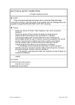
Warning
If all of the applied parts correspond to the instrument type, the applied
parts will be tied together and one reading will be taken. If any of the applied
parts differ from the instrument type, all applied parts will be tested
individually, based on the type of applied part. This applies to Auto and Step
modes only.
Perform the Test
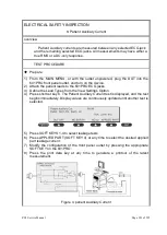
1) From the MAIN MENU, or with the outlet unpowered, plug the DUT into the
601PRO front panel outlet, and turn on the device.
2) Attach the applied parts to the 601PRO's applied part terminals.
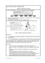
3) Press shortcut key 6. The Patient Leakage test is displayed, and the test begins
immediately.
4) Press APPLIED PART (SOFT KEY 4) at any time to select the desired applied
part leakage current.
5) Modify the configuration of the front panel outlet by pressing the appropriate
SOFT KEY on the 601PRO.
Содержание Zonare ZS3
Страница 1: ...ZS3 Diagnostic Ultrasound System Service Manual ...
Страница 34: ...ZS3 Service Manual Page 34 of 295 4 System Overview Major System Assemblies Figure 4 1 ZS3 System ...
Страница 120: ...ZS3 Service Manual Page 120 of 295 FTP Setup Enters Setup Network FTP ...
Страница 124: ...ZS3 Service Manual Page 124 of 295 ...
Страница 131: ...ZS3 Service Manual Page 131 of 295 13 System Diagrams ...
Страница 132: ...ZS3 Service Manual Page 132 of 295 Power Block Diagram Figure 13 1 ZS3 Power Block Diagram ...
Страница 133: ...ZS3 Service Manual Page 133 of 295 Cabling Diagram Figure 13 2 ZS3 Cabling Diagram ...
Страница 134: ...ZS3 Service Manual Page 134 of 295 System Block Diagram Figure 13 3 ZS3 Overall System Block Diagram ...
Страница 138: ...ZS3 Service Manual Page 138 of 295 Figure 14 6 ZS3 ...
Страница 157: ...ZS3 Service Manual Page 157 of 295 8 The system performs the second automatic reboot and enters the following page ...
Страница 185: ...ZS3 Service Manual Page 185 of 295 17 Preventative Maintenance Forms ...
Страница 217: ...ZS3 Service Manual Page 217 of 295 Figure 18 8 ZS3 ...
Страница 252: ...ZS3 Service Manual Page 252 of 295 Figure 19 43 ZS3 Power Cable USB Cable ...
Страница 295: ...P N 046 014026 00 2 0 ...

