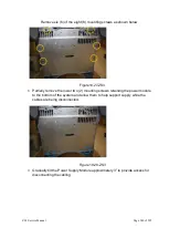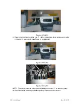
ZS3 Service Manual
Page 226 of 295
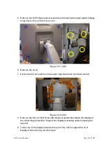
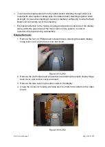
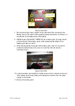
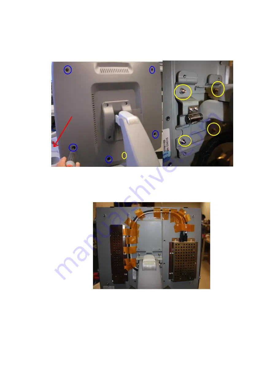
5. Remove the (6) Phillips-head screws that are retaining the larger plastic display
hinge back cover, and remove cover.
Figure 19.11-ZS3
6. Remove the cover.
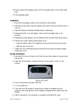
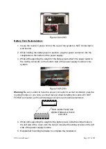
7. Disconnect the two cables on the upper right hand side (as shown below).
Figure 19.12-ZS3
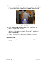
8.
Remove the four (4) 9/32” Nuts with captive washers that attach the display to
the metal hinge assembly. Support the Display Assembly while loosening the
last bolt.
9. Tilt the top of the display towards the rear of the cart to support the LCD
Display while removing the last screw.
Содержание Zonare ZS3
Страница 1: ...ZS3 Diagnostic Ultrasound System Service Manual ...
Страница 34: ...ZS3 Service Manual Page 34 of 295 4 System Overview Major System Assemblies Figure 4 1 ZS3 System ...
Страница 120: ...ZS3 Service Manual Page 120 of 295 FTP Setup Enters Setup Network FTP ...
Страница 124: ...ZS3 Service Manual Page 124 of 295 ...
Страница 131: ...ZS3 Service Manual Page 131 of 295 13 System Diagrams ...
Страница 132: ...ZS3 Service Manual Page 132 of 295 Power Block Diagram Figure 13 1 ZS3 Power Block Diagram ...
Страница 133: ...ZS3 Service Manual Page 133 of 295 Cabling Diagram Figure 13 2 ZS3 Cabling Diagram ...
Страница 134: ...ZS3 Service Manual Page 134 of 295 System Block Diagram Figure 13 3 ZS3 Overall System Block Diagram ...
Страница 138: ...ZS3 Service Manual Page 138 of 295 Figure 14 6 ZS3 ...
Страница 157: ...ZS3 Service Manual Page 157 of 295 8 The system performs the second automatic reboot and enters the following page ...
Страница 185: ...ZS3 Service Manual Page 185 of 295 17 Preventative Maintenance Forms ...
Страница 217: ...ZS3 Service Manual Page 217 of 295 Figure 18 8 ZS3 ...
Страница 252: ...ZS3 Service Manual Page 252 of 295 Figure 19 43 ZS3 Power Cable USB Cable ...
Страница 295: ...P N 046 014026 00 2 0 ...

