Wall formwork
Mammut 350
Stripping corner
Description
Ref. No.
M 350 stripping corner
350/25...................................
23-151-00
300/25...................................
23-151-10
250/25...................................
23-151-20
125/25...................................
23-151-30
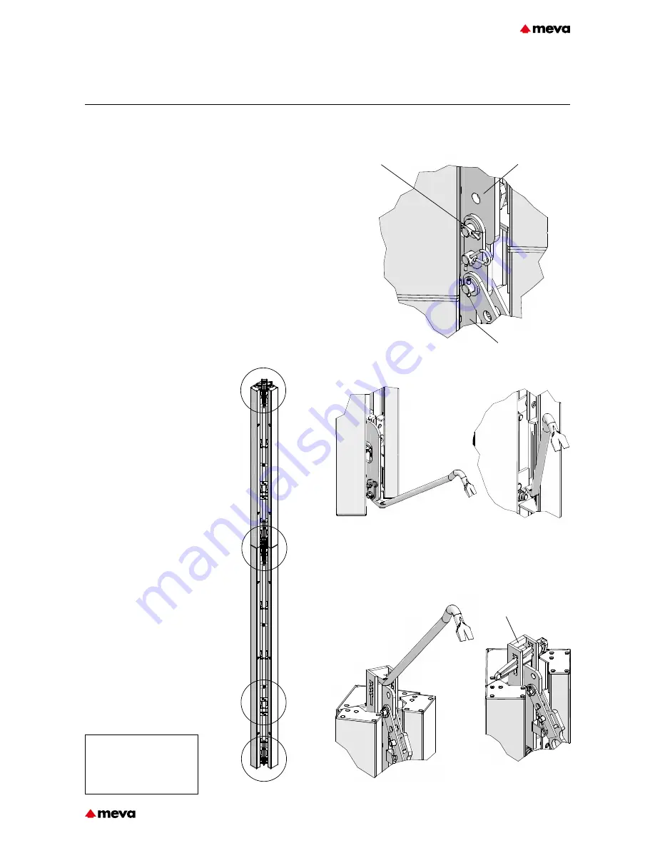
Fig. 31.2
Fig. 31.3
Fig. 31.4
Fig. 31.5
Fig. 31.6
Pouring position
Fig. 31.1
A
B
D
C
Bell-crank lever
Bell-crank lever
Bolt with cotter pin
Set-up and handling
1. Insert the wedge integrated
into the stripping corner into the
connecting device (Position C,
Fig. 31.6).
2. Connect the stripping cor-
ners and panels (see pages
M350-28 and -30)
.
3. Remove the wedges after
pouring and prior to stripping.
4. Activate the stripping corner
with a crowbar. The bell-crank
lever is pushed upwards using
the crowbar. The crowbar can be
applied at the bottom at position
A (Fig. 31.3) or in the middle at
position B (Fig. 31.4). This breaks
the bond between the formwork
facing and the concrete without
much effort.
Pages M350-32 and -33
describe how to activate the
stripping corner with the strip-
ping support.
5. Attach the stripping corners
with crane slings to the crane
gear. Make sure the entire form-
work is completely removed from
the poured walls before lifting it
by crane.
6. The entire formwork is moved
in one single lift and detached
from the crane when it is in its
new position.
7. The stripping corner can be
reset for the next pour by posi-
tioning the crowbar at position
C (Fig. 31.5) and pushing the
bell-crank lever down.
8. Reinsert the wedge into the
connecting device (Fig. 31.6).
9. A few hammer blows to the
wedge will move the lateral parts
of the stripping corner outwards
and keep them in the pouring
position.
Height extension
Two stripping corners can be
connected to each other easily by
joining their bell-crank levers. The
integrated pin must be secured
with the cotter pin (Position D,
Fig. 31.1).
Connecting device
Position D
Position B
Position C
Position B
M350-31
Technical Instruction Manual / Status November 2018


