Wall formwork
Mammut 350
Stripping corner
Description
Ref. No.
M 350 stripping corner
350/25..................................
23-151-00
300/25...................................
23-151-10
250/25..................................
23-151-20
125/25..................................
23-151-30
Adhesive tape .......................
41-912-10
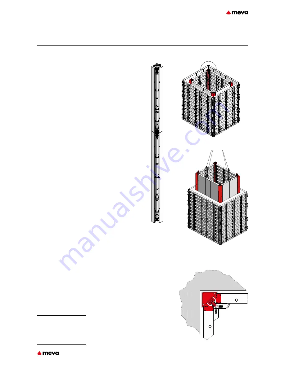
Fig. 27.1
Fig. 27.2
Fig. 27.3
Fig. 27.4 Detail A
A
The M stripping corners 350
(Fig. 27.1), 300, 250 and 125
allow the formwork to be
removed safely and quickly from
poured shaft walls, for example,
without damaging the walls
or formwork. They function
according to the “jumping jack”
principle.
The stripping corner is a three-
piece design to permit inward
movement of the lateral parts.
(Fig. 27.4)
The side length is 25 cm.
The height of the stripping
corner can be increased easily
(Fig. 27.1).
After pouring and when the
concrete has set sufficiently,
the entire shaft formwork can
be detached from the con-
crete by activating all stripping
corners (Fig. 27.2 and pages
M350-31 to -33). The
shaft formwork can then be
lifted out in one piece by crane
(Fig. 27.3). The formwork must
be completely detached from the
concrete before it can be lifted
out by crane.
Note
Before pouring, cover the joints
on the sides of the stripping cor-
ner with adhesive tape to make it
easier to clean.
Attention
When slinging with several
strands, only two strands may be
considered to be load-bearing
according to the Berufsgenossen-
sachft (the German employers'
liability insurance association).
This does not apply if it has been
ensured that the load is distrib-
uted evenly over further strands
or if the permissible loading
of the individual strands is not
exceeded in the event of an
unequal load distribution.
The maximum permissible load-
ing of the crane eye per strip-
ping corner is 10 kN (1 tons).
This results in a permissible total
weight of the complete shaft
formwork of 40 kN (4 tons) if it
has been ensured that the load
is evenly distributed (the con-
tractor is responsible for this).
Otherwise, the permissible total
weight is 20 kN (2 tons).
The permissible loading of the M
crane hook is 15 kN (1.5 tons).
This results in a permissible total
weight of the complete shaft
formwork of 60 kN (6 tons) if it
has been ensured that the load
is evenly distributed (the con-
tractor is responsible for this).
Otherwise, the permissible total
weight is 30 kN (3 tons).
For higher loads, a spreader
beam must be used.
M350-27
Technical Instruction Manual / Status November 2018


