Page 52
5.2 Functions of the ARS 2100 SE series servo drives
5.2.1 Compatibility
For compatibility reasons, from the user’s point of view, the control structure of the ARS 2100 SE
series servo drive has mostly the same characteristics, interfaces and parameters as the previous
ARS family.
PWM
M
Positioning
controller
Speed
controller
Current
controller
Power
stage
Motor
Angle encoder
1 and 2
Actual value management
X2A
X2B
X10
Set point management:
- Analogue inputs
- Fixed values
- Synchronization
- Ramp generator
Positioning control and
Interpolation
Trajectories calculation:
- Reference position
- Motorspeed precontrol
- Motorcurrent precontrol
E1
E2
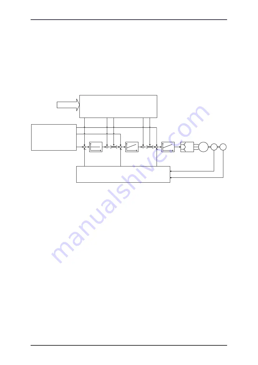
Figure 2:
Control scheme of the ARS 2100 SE
shows the basic control structure of the ARS 2100 SE. Current controller, speed controller
and positioning controller are arranged in a cascade. Due to the rotor-oriented control principle the
current can be set separated in active current (i
q
) and reactive current (i
d
). Therefore there are two
current controllers, both of them PI controllers. To provide a better overview, however, the i
d
controller
The planned basic modes of operation are torque control, speed control and positioning.
Functions such as synchronisation, “flying saw” and so on are variants of these basic modes of
operation.
Furthermore, individual functions of these modes of operation can be combined with each other, for
example torque control with speed limitation.
5.2.2 Pulse width modulation (PWM)
The ARS 2100 SE series servo drives are able to vary the clock frequency in the current controller
circuit. In most cases the settings can be made using the parameterisation software Metronix
ServoCommander
®
. In order to minimize switching losses, the clock of the pulse width modulation can
be cut in half as compared to the frequency in the current controller circuit.
Product Manual „Servo drives ARS 2100 SE“
Version 5.0


