52
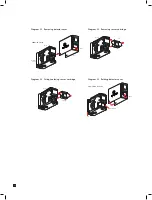
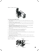
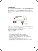
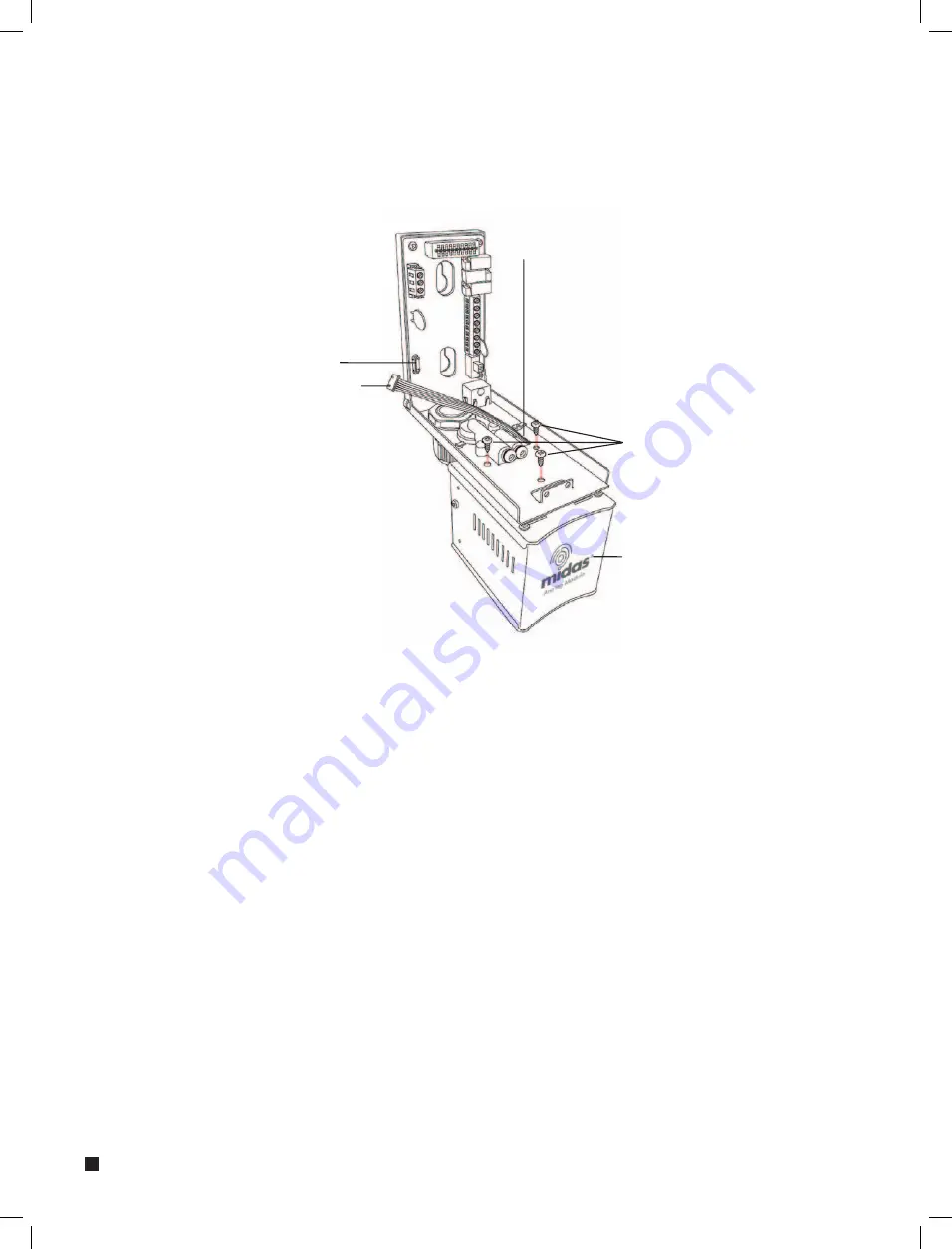
Diagram 39. Analog module connection.
Rectangular access
at bottom of bracket
Mounting screws (x3)
Socket
Connector
Analog module
11.2 RE-ASSEMBLING THE MIDAS
®
DETECTOR
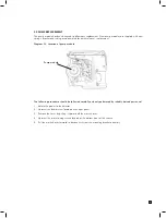
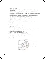
1. Align the PCB at the top rear of the main chassis with the connector located at the top of the mounting
bracket assembly.
2. At the same time align the two tubes at the bottom rear of the main chassis with the two tubes located on the
bottom of the mounting bracket assembly.
3. Slide the chassis backwards on the mounting bracket assembly so that the PCB, connector and tubes engage
simultaneously.
4. Ensure the PCB connector and tubes are fully engaged by firmly pushing the main chassis horizontally
backwards on the mounting bracket assembly
(WARNING: DO NOT PUSH ON THE LCD AS THIS MAY CAUSE DAMAGE).
5. Align the two fixing screws located at the bottom of the chassis with the screw threads on the mounting
bracket assembly.
6. Tighten the screws to secure the chassis to the mounting bracket assembly.
7. Fit the dummy sensor (optional accessory MIDAS-A-013) as per Section 9.1.1
8. Switch the power switch on the terminal module to the ‘on’ position
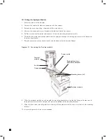
9. Refit the Detector’s cover by aligning the slots either side with the locating tabs on the mounting bracket
assembly.
10. Push the cover horizontally until home.
11. Tighten the thumbscrew located on the front panel.
Содержание midas
Страница 1: ...1 TOXIC FLAMMABLE AND OXYGEN GAS DETECTOR OP E RAT ING INSTRUCTIONS ...
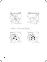
Страница 44: ...44 6 Remove the 4 pump module screws 7 Remove the two fixing clips and disconnect the tubes at the manifold ...
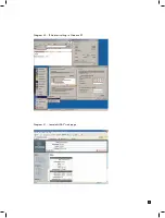
Страница 55: ...55 Diagram 40 IP Address setting in Windows XP Diagram 41 Sample MIDAS web page ...
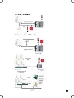
Страница 57: ...57 15 2 Modbus TCP Installation 15 3 Power over Ethernet POE Installation ...


