50
Diagram 36 shows in a simple form how the gas sample is drawn through the pyrolyzer module by the pump
(located at the end of the gas path) and is first routed to the pyrolyzer via the freon filter before being resent to
the gas sensor cartridge, where the gas measurement is taken. The sample continues via the flow-meter through
the dust filter and is finally exhausted from the instrument. Adjustment of the gas flow through the instrument is
done automatically. To perform a flow calibration refer to section 8.3.3.
Diagram 36. Pyrolyzer configuration gas flow
����������������
����������������
����������
�����
����������
�������
����
������������
���������������
������������
������������������������
�������
�������������
����������
��������������������
������������������
Diagram 37 shows in diagrammatic form how the gas sample flows through the various components. It shows
how the instrument controls, monitors and measures the gas sample flow and signals any fault conditions to the
user via the LCD screen, e.g. due to flow problems caused by pump failure, or failure of the pyrolyzer unit, etc.
Diagram 37. Pyrolyzer option flow diagram
Pyrolyzer
Gas Sensor
Sample Inlet
500 ml/min
Pyrolyzer Flow rate
50 ml/min
Voltage/
Current
Sensing
Driver
Heater
Heater Controller
Pyrolyzer Option
heater voltage/current
sensing system to detect
Heater Controller utilizes
element failure and out of
conditions such as heater
temperature range.
Bypass flow
Flow Controller
Pump Drive
Pressure
Sensing
Pyro Fault
Flow Fault
Sensor
Pressure
Pump
Exhaust
Sample
Flow Controller utilizes differential
pressure over laminar flow element
to monitor flow conditions.
Element
Laminar Flow
Gas Sample Flow
Signal/Control Flow
Dust
Filter
Particulate
Freon/
Filter
MIDAS Transmitter
Main
Control PCB
450 ml/min
Содержание midas
Страница 1: ...1 TOXIC FLAMMABLE AND OXYGEN GAS DETECTOR OP E RAT ING INSTRUCTIONS ...
Страница 44: ...44 6 Remove the 4 pump module screws 7 Remove the two fixing clips and disconnect the tubes at the manifold ...
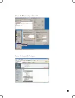
Страница 55: ...55 Diagram 40 IP Address setting in Windows XP Diagram 41 Sample MIDAS web page ...
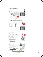
Страница 57: ...57 15 2 Modbus TCP Installation 15 3 Power over Ethernet POE Installation ...

