32
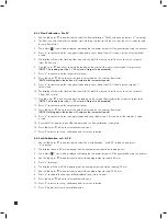
15. Use the ‘
▲
’ up or ‘
▼
’ down buttons to change the alarm on time delay (seconds).
16. Press ‘
✓
’ to display the flashing alarm relay latching (L) or non latching (nL) setting.
17. Use the ‘
▲
’ up or ‘
▼
’ down buttons to change between the settings.
18. Press ‘
✓
’ to display the flashing alarm relays normally energized (nE) or normally de-energized (nd) setting.
19. Use the ‘
▲
’ up or ‘
▼
’ down buttons to change between the settings.
20. Press ‘
✓
’ to update all the changes (UPdt displayed) and return to step 1.
21. Press ‘
▲
’ up or ‘
▼
’ down to select another submenu.
22. Press ‘X’ to return to set-up, calibration and test menu selection.
23. Press ‘X’ again to return to normal operation.
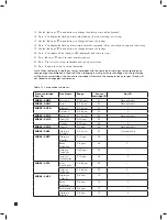
Note: When replacing a single gas sensor cartridges with the same type single gas sensor cartridge, no
change of gas confirmation is required. When changing a multi gas sensor cartridge with the same type
multi gas sensor cartridge, the new sensor cartridge will assume the same previously set gas ID and will
not request a change gas confirmation.
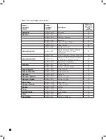
Sensor cartridge
Part No.
Gas Name
Range
Sensor
cartridge ID
Gas ID
MIDAS-S-NH3
Ammonia
0-100 ppm
01
Not applicable
MIDAS-S-ASH
Arsine
0-0.2 ppm
02
Not applicable
MIDAS-S-HYD
Diborane
0-0.4 ppm
03
1
Germane
0-0.8 ppm
03
2
MIDAS-S-PH3
Phosphine
0-1.2 ppm
04
Not applicable
MIDAS-S-SHX
Silane(20)
0-20 ppm
05
1
Disilane
0-20 ppm
05
2
MIDAS-S-SHL
Silane(2)
0-2 ppm
06
Not applicable
MIDAS-S-HSE
Hydrogen
Selenide
0-0.
4
ppm
0
7
N
ot applicable
MIDAS-S-HFX
Hydrogen
Fluoride
0-12 ppm
08
1
Boron
Trifluoride
0-
8
ppm
0
8
2
Nitrogen
Trifluoride
0-40 ppm
08
3
Tungsten
Hexafluoride
0-12 ppm
08
4
MIDAS-S-SF4
Sulfur
Tetrafluoride
0-0.
8
ppm
0
9
1
Chlorine
Trifluoride
0-0.
8
ppm
0
9
2
MIDAS-S-HCL
Hydrogen
Chloride
0-8 ppm
10
1
Boron
Trichloride
0-8 ppm
10
2
Dichlorosilane
0-8 ppm
10
3
Hydrogen
Bromide
0-8 ppm
10
4
Table 13. Set-up mode submenus.
Содержание midas
Страница 1: ...1 TOXIC FLAMMABLE AND OXYGEN GAS DETECTOR OP E RAT ING INSTRUCTIONS ...
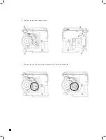
Страница 44: ...44 6 Remove the 4 pump module screws 7 Remove the two fixing clips and disconnect the tubes at the manifold ...
Страница 55: ...55 Diagram 40 IP Address setting in Windows XP Diagram 41 Sample MIDAS web page ...
Страница 57: ...57 15 2 Modbus TCP Installation 15 3 Power over Ethernet POE Installation ...

