39
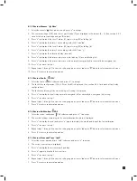
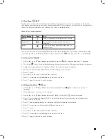
8.4 Test Menu ‘
tEST’
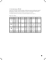
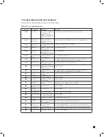
The test menu is used to test the detector gas reading using bump test gas, and for simulation of alarm and
fault display and output operation (relay, analog and digital). The test submenu also includes the detector inhibit
facility. The test menu comprises of 3 submenus as shown in the table below.
Test submenu
Icon
Test
Bump
Bump test detector with inhibited alarm outputs
Alarm/Fault
Test the alarm and fault display and output
operation
Inhibit
Put the unit into/out of an inhibit state and set
inhibit time out
Table 18. Test mode submenus.
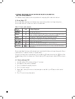
To select the test menu from normal operation, press the ‘
▲
’ up button for a few seconds. Enter the pass code
(if set). Use the ‘
▲
’ up or ‘
▼
’ down buttons to select the test menu ‘
’ icon and press the ‘
✓
’ accept button.
8.4.1 Bump Test ‘ bUmP’
1. Use the ‘
▲
’ up or ‘
▼
’ down buttons to select the bump test ‘ bUmP’ submenu and press ‘
✓
’ to accept.
2. The inhibit ‘
’ icon is also displayed indicating that no alarm outputs will be generated during this process.
3. Apply the bump test gas and the display will show the measured gas concentration.
4. Remove the bump test gas and allow the detector reading to return to zero.
5. Press ‘X’ to exit.
6. Press ‘
▲
’ up or ‘
▼
’ down to select another submenu.
7. Press ‘X’ to return to set-up, calibration and test menu selection.
8. Press ‘X’ again to return to normal operation.
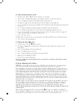
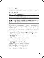
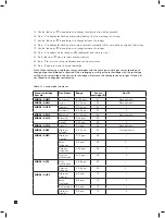
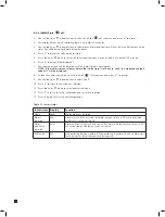
8.4.2 Alarm/Fault Test ‘
Si m’
1. Use the ‘
▲
’ up or ‘
▼
’ down buttons to select the alarm/fault test ‘
Si m’ submenu and press ‘
✓
’
to accept.
2. The display shows ‘Si m’ and the A1 ‘
▲
’ icon.
3. Use the ‘
▲
’ up or ‘
▼
’ down buttons to select A1 ‘
▲
’, A2 ‘ ’ or Fault ‘
’ for test simulation.
4. Press ‘
✓
’ to select and the displays ‘SurE’ to indicate that the next step will activate the selected output
(relay, analog and digital)
5. Press ‘
✓
’ and the display flashes ‘on’ indicating that the selected output is activated
6. Press ‘X’ to return to step 2 and select a different output for test.
7. Press ‘X’ to exit.
8. Press ‘
▲
’ up or ‘
▼
’ down to select another submenu.
9. Press ‘X’ to return to set-up, calibration and test menu selection.
10. Press ‘X’ again to return to normal operation.
Содержание midas
Страница 1: ...1 TOXIC FLAMMABLE AND OXYGEN GAS DETECTOR OP E RAT ING INSTRUCTIONS ...
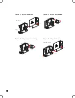
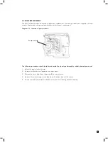
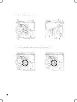
Страница 44: ...44 6 Remove the 4 pump module screws 7 Remove the two fixing clips and disconnect the tubes at the manifold ...
Страница 55: ...55 Diagram 40 IP Address setting in Windows XP Diagram 41 Sample MIDAS web page ...
Страница 57: ...57 15 2 Modbus TCP Installation 15 3 Power over Ethernet POE Installation ...

