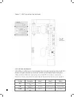
21
7 GENERAL OPERATION
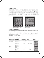
After applying power to the detector, the display will go through a start up test routine illuminating in sequence
all the LEDs, icons and digits of the display. The display will show the message ‘WAIT’ and ‘LOAD’ as it checks
for cartridge data. It will then display the message ‘WARM’ until the sensor cartridge to reaches operating
temperature. When complete the detector will enter normal monitoring mode indicated by the ‘ ’ icon on the
display cycling through three states (2 rings, 3 rings, 4 rings). The measured gas concentration will be shown
on the display and transmitted on the 4-20 mA output. The green LED will flash once every second indicating
power and the sample flow rate indicator will be displayed. If monitoring is interrupted due to a fault, a test or
calibration process or a user requested inhibit, the ‘ ’ icon will flash. For details of fault and maintenance fault
codes refer to section 12.
Final Start Up Routine Screen
Normal Operation
7.1 Normal Operation Mode
In this mode the detector displays gas concentration, alarm, fault and status information via its backlit LCD and
front panel LEDs. Typical normal operation display and output states are shown below. See Section 12 for a full
list of fault codes.
NOTE: The examples below are for a linear 4-20 mA output over a full scale range of 2 ppm. The current
output for a given gas concentration will be different for other full scale ranges (linear 4 mA = 0 % full
scale to 20 mA = 100 % full scale).
See section 12 for a full list of fault codes.
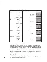
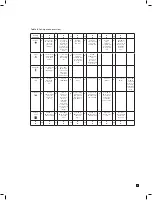
Operational State Relay status
4-20 mA output
(for 2ppm range)
LEDs
Display*
Normal operation
Alarm relay 1
de-activated
Alarm relay 2
de-activated
Fault relay activated
4 mA
Green slow flash
Alarm 1
Alarm relay 1
activated
Alarm relay 2
de-activated
Fault relay activated
6 mA
Green slow flash
Red on
Table 6. Normal operation display and output states.
Содержание midas
Страница 1: ...1 TOXIC FLAMMABLE AND OXYGEN GAS DETECTOR OP E RAT ING INSTRUCTIONS ...
Страница 44: ...44 6 Remove the 4 pump module screws 7 Remove the two fixing clips and disconnect the tubes at the manifold ...
Страница 55: ...55 Diagram 40 IP Address setting in Windows XP Diagram 41 Sample MIDAS web page ...
Страница 57: ...57 15 2 Modbus TCP Installation 15 3 Power over Ethernet POE Installation ...


