12
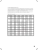
5.3 Sample and exhaust tubing calculations
The following tables show the flow rate, tubing length, transport time, and maximum pressure and vacuum at the
inlet and exhaust points.
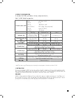
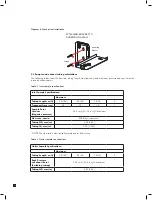
Table 2. Inlet sample specifications
Inlet Sample Specifications:
Maximum
Tubing Length, m (ft)
30 (100)
20 (66)
10 (33)
0
Transport Time (sec)
28
19
10
1
Sample Point
Vacuum
(Negative pressure)
-25.4 cm H
2
O (-10 in H
2
O) Maximum
Flow rate, cc/min.
500 (Flow is constant)
1
Tubing OD, mm (in)
6.35 (0.25)
Tubing ID, mm (in)
3.18 (0.125)
1
NOTE: The flow rate is electronically maintained at 500 cc/min
Table 3. Outlet sample specifications
Outlet Sample Specifications:
Maximum
Tubing Length, m (ft)
30 (100)
20 (66)
10 (33)
0
Back Pressure
at Exhaust Point
(Excluding tubing)
20.3 cm H
2
O (8 in H
2
O) Maximum
Tubing OD, mm (in)
6.35 (0.25)
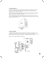
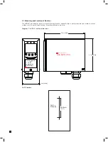
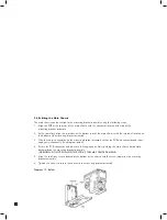
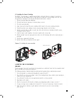
Diagram 8. Mechanical installation
ATTACHING BRACKET TO
SCREWS ON A WALL
mounting
bracket
screws
Содержание midas
Страница 1: ...1 TOXIC FLAMMABLE AND OXYGEN GAS DETECTOR OP E RAT ING INSTRUCTIONS ...
Страница 44: ...44 6 Remove the 4 pump module screws 7 Remove the two fixing clips and disconnect the tubes at the manifold ...
Страница 55: ...55 Diagram 40 IP Address setting in Windows XP Diagram 41 Sample MIDAS web page ...
Страница 57: ...57 15 2 Modbus TCP Installation 15 3 Power over Ethernet POE Installation ...


