34
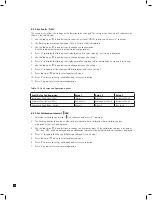
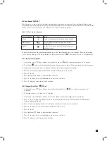
8.2.3 Set Faults ‘
FLt’
The set-up menu allows the settings of the detector to be changed. The set-up menu consists of 6 submenus as
shown in the table below.
1. Use the ‘
▲
’ up or ‘
▼
’ down buttons to select the set faults ‘
FLt’ submenu and press ‘
✓
’ to accept.
2. The flashing fault relay configuration (1FLt, 2 FLt or CmbF) is displayed.
3. Use the ‘
▲
’ up or ‘
▼
’ down buttons to change the configuration.
(See the table below for details of fault relay configurations)
4. Press ‘
✓
’ to display the flashing fault relay latching (L) or non latching (nL) setting is displayed.
5. Use the ‘
▲
’ up or ‘
▼
’ down buttons to change between the settings.
6. Press ‘
✓
’ to display the flashing fault relay normally energized (nE) or normally de-energized (nd) setting.
7. Use the ‘
▲
’ up or ‘
▼
’ down buttons to change between the settings.
8. Press ‘
✓
’ to update all the changes (UPdt displayed) and return to step 1.
9. Press ‘
▲
’ up or ‘
▼
’ down to select another submenu.
10. Press ‘X’ to return to set-up, calibration and test menu selection.
11. Press ‘X’ again to return to normal operation.
Table 14. Fault relay configuration options.
Fault Relay Configuration
Relay 1
Relay 2
Relay 3
Instrument Fault Only (1FLt)
Alarm 1
Alarm 2
Instrument Fault
Separate Fault Relays (2FLt)
Any Alarm
Maintenance Fault
Instrument Fault
Combined Fault Relay (CmbF)
Alarm 1
Alarm 2
Any Fault
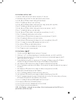
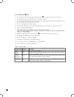
8.2.4 Set Calibration Interval ‘ CAL’
1. Select the set calibration interval ‘ CAL’ submenu and press ‘
✓
’ to accept.
2. The flashing display shows the number of days interval after a calibration that a calibration due
maintenance fault will be displayed.
3. Use the ‘
▲
’ up or ‘
▼
’ down buttons to change the number of days. (If the calibration interval is set below
‘001’ then ‘OFF’ will be displayed and no calibration interval will be activated and no reminders displayed)
4. Press ‘
✓
’ to update the change (UPdt displayed) and return to step 1.
5. Press ‘
▲
’ up or ‘
▼
’ down to select another submenu.
6. Press ‘X’ to return to set-up, calibration and test menu selection.
7. Press ‘X’ again to return to normal operation
Содержание midas
Страница 1: ...1 TOXIC FLAMMABLE AND OXYGEN GAS DETECTOR OP E RAT ING INSTRUCTIONS ...
Страница 44: ...44 6 Remove the 4 pump module screws 7 Remove the two fixing clips and disconnect the tubes at the manifold ...
Страница 55: ...55 Diagram 40 IP Address setting in Windows XP Diagram 41 Sample MIDAS web page ...
Страница 57: ...57 15 2 Modbus TCP Installation 15 3 Power over Ethernet POE Installation ...

