background image

41

9 ROUTINE MAINTENANCE

MIDAS

®

 is a fully serviceable product designed with modular components that can be readily replaced by trained 

service personnel so as to minimize the time that the gas detector is not available. 

External in-line air filters should be replaced every three months or more frequently if the system is sampling in 

environments that have high levels of particulate matter or very acidic / wet atmospheres. Similarly the internal 

particulate filter should be replaced once a year or more frequently if the sample lines are prone to heavy 

contamination.

Every sensor cartridge is shipped with a 12 month warranty and an extended 2 year warranty is also available 

for purchase. All sensor cartridges are factory calibrated to traceable national standards before shipment to the 

end user.

Note that testing or calibrating with the wrong (incorrect, out of date, non-traceable) calibration gases, 

calibration equipment, methods or operating conditions can actually damage the sensor cartridge’s lifetime and 

alter the calibration adversely. Only qualified calibration technicians should attempt to calibrate the MIDAS

®

 gas 

detector.

NOTE: For details regarding sensor cartridge calibration and bump testing method refer to 

section 18.

The internal pump module is designed to operate for a minimum of 18 - 24 months and it is recommended that 

this pump module (part number MIDAS-A-007) be replaced every 2 years.

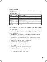
9.1 Sensor Cartridge Replacement

To avoid the possibility of unwanted alarms or faults Zellweger Analytics recommend that the sensor cartridge be 

replaced without power to the MIDAS

®

 unit. If fitting a sensor cartridge to a unit that is powered, please refer to 

section 8.4.3 to inhibit the detectors outputs. 

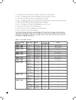
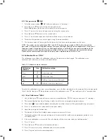
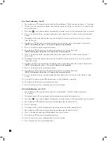
9.1.1 Sensor Cartridge Fitting/Replacement

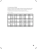
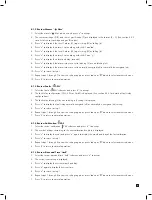
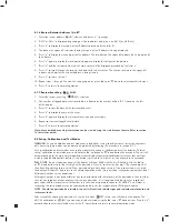
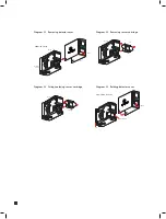
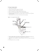
1.    Unscrew the thumbscrew located on the front panel and remove the cover by pulling it forwards off the main 

chassis (see diagram 22).

2.   Ensure the power switch on the terminal module is in the off position.

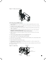
3.    Remove the old sensor cartridge from the unit (if fitted) by unclipping the two sensor cartridge locking  

tabs located either side of the sensor cartridge and using them to firmly pull the sensor cartridge out  

(see diagram 23).

4.   Fit the new sensor cartridge by aligning the pins at the top of the sensor cartridge with the socket in the 

sensor cartridge chamber.

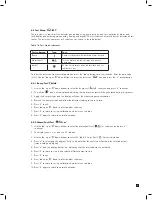
5.    Carefully push the sensor cartridge into the sensor cartridge chamber until fully home and lock in place 

using the tabs either side of the sensor cartridge (see diagram 24). 

6.   Switch the power switch on the terminal module to the ‘on’ position.

7.    Refit the detector’s cover by aligning the slots either side with the locating tabs on the mounting bracket 

assembly and pushing the cover horizontally until home. Tighten the thumbscrew located on the front panel 

(see diagram 25). 

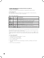
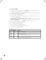
NOTE: If replacing a sensor cartridge with a different gas type sensor cartridge the display will scroll the 

message ‘CHANGE GAS?’ If you are changing the sensor cartridge gas type press ‘

’ to accept. If not, fit 

the correct sensor cartridge. The pass code (if set) must be entered to change sensor cartridge gas type.  

To set the correct gas for a multi gas type sensor cartridge refer to section 8.2.2.

Содержание midas

Страница 1: ...1 TOXIC FLAMMABLE AND OXYGEN GAS DETECTOR OP E RAT ING INSTRUCTIONS ...

Страница 2: ...17 5 8 Refitting the main chassis 18 5 9 Installing the sensor cartridge 19 6 Detector start up procedures 19 7 General operation 21 7 1 Normal operation mode 21 7 1 1 Resetting alarms faults and maintenance faults 22 7 2 Review mode 22 7 2 1 Review mode menu overview 23 7 3 Overview of set up calibration and test mode 24 7 3 1 Set up menu overview 24 7 3 2 Calibration menu overview CAL 26 7 3 3 T...

Страница 3: ... Sensor cartridge fitting replacement 41 9 2 Pump replacement 43 9 3 Re assembling the detector 46 9 4 Filter replacement 46 10 Pyrolyzer module option 47 10 1 Fitting the pyrolyzer module 48 10 2 Re assembling the MIDAS detector 49 11 Analog module 51 11 1 Fitting the analog module 51 11 2 Re assembling the MIDAS detector 52 12 Trouble shooting and fault diagnosis 53 13 REFLEX 54 14 Internal web ...

Страница 4: ...op level 69 20 2 Review mode 70 20 3 Review software info alarm fault and gas calibration 71 20 4 Review date time and network 72 20 5 Review event log 73 20 6 Set up mode 74 20 7 Set up alarm fault and gas calibration 75 20 8 Set up date time and network 76 20 9 Set up pass code 77 20 10 Calibration mode 78 20 11 Calibration gas zero and span 79 20 12 Calibration Flow calibration 80 20 13 Calibra...

Страница 5: ...er and communications capabilities built in as standard These include 3 on board relays 0 22 mA analog output Modbus TCP outputs for signal and service connectivity as well as the innovative Power over Ethernet PoE protocol that enables a single Ethernet connection to be made for all power control and communication requirements 3 PRODUCT OVERVIEW The MIDAS gas detector comprises of 4 parts the mai...

Страница 6: ...tion alarm and system status In set up review calibration and test modes the LCD shows the relevant menu options These menus are simply navigated using the up down accept and X cancel buttons 1 Red alarm LED 2 Normal operation icon 3 Review mode icon 4 Green power LED 5 Set up mode icon 6 Calibration mode icon 7 Yellow Fault LED 8 Test mode icon 9 Gas concentration and message display area 10 Disp...

Страница 7: ...as well as providing the chamber where the sensor cartridge is exposed to the sampled gas For details of fitting sensor cartridge refer to section 5 9 3 2 Mounting Bracket Assembly The mounting bracket assembly comprises of the detector mounting bracket the terminal module the gas sample inlet and outlet ports the cable conduit entry and Ethernet communications socket Diagram 4 Mounting bracket as...

Страница 8: ...tion Should a bias voltage not be applied e g during a power failure then the cell will take a longer time to recover before effective gas detection can take place The longer the loss of applied power the longer the recovery time Refer to the relevant sensor cartridge data sheet for information on each sensor cartridge In order to avoid the risk of loss of gas detection due to unforeseen power los...

Страница 9: ...nergizes on fault Contact Normally Open NO Latching Non latching Alarm and fault relays automatically reset when reading falls below alarm thresholds or fault clears Pass code No pass code set As standard the MIDAS gas detector is factory configured as below Table 1 MIDAS default configuration 1 MIDAS detectors are not ETL approved for monitoring in or sampling from classified areas above 25 LEL 5...

Страница 10: ...table vertical surface such as a wall tool housing mounting plate on a pole etc Nitrogen Trifluoride NF3 FS 4 40 PPM PN MIDAS X HFX SN 2564 0243 Expires Nov2006 zellweger analytics z zellweger analytics z GAS DETECTOR midas 5 91 150 00 4 72 120 00 2 48 63 00 Diagram 7 MIDAS outline dimensions Drill Template Drill 2 x M4 holes 58 50mm 2 3 ...

Страница 11: ... the inlet filter for local monitoring 10 Take into consideration the space required for cable or conduit access 5 2 Mechanical Installation The following steps and diagrams show how to separate the mounting bracket assembly from the main chassis and mount it on a vertical flat surface 1 Unscrew the thumbscrew located on the front panel 2 Remove the cover by pulling it forwards off the main chassi...

Страница 12: ...int Vacuum Negative pressure 25 4 cm H2 O 10 in H2 O Maximum Flow rate cc min 500 Flow is constant 1 Tubing OD mm in 6 35 0 25 Tubing ID mm in 3 18 0 125 1 NOTE The flow rate is electronically maintained at 500 cc min Table 3 Outlet sample specifications Outlet Sample Specifications Maximum Tubing Length m ft 30 100 20 66 10 33 0 Back Pressure at Exhaust Point Excluding tubing 20 3 cm H2 O 8 in H2...

Страница 13: ...ride 5 NO YES Bromine 10 NO YES Carbon Dioxide 30 YES Carbon Monoxide 30 YES Chlorine 10 NO YES Chlorine Dioxide 10 NO YES Chlorine Trifluoride 5 NO YES Diborane 30 YES Dichlorosilane 5 NO YES Disilane 10 YES Fluorine 10 NO YES Germane 30 YES Hydrogen LEL 30 YES Hydrogen ppm 30 YES Hydrogen Bromide 5 NO YES Hydrogen Chloride 5 NO YES Hydrogen Cyanide 10 YES Hydrogen Fluoride 5 NO YES Hydrogen Sele...

Страница 14: ...nected to the sensor cartridge gas inlet port The external dust filter part number is 780248 for normal gases and 1830 0055 for corrosive gases The area around the detector is then being monitored as opposed to a sample being drawn from a remote location Diagram 9 Local gas detector option MIDAS T 001 transmitter installed with in line particulate filter for local ambient monitoring mode Recommend...

Страница 15: ...ice then 24 VDC power must not also be connected to the device or conversely if 24 VDC is used to power the MIDAS then electrical power via the Ethernet port must not be applied Failure to observe this requirement may cause damage to the gas detection system and will not be covered by the standard warranty When connecting the wires ensure that the power switch is in the off position Diagram 11 sho...

Страница 16: ...EMENTS If the MIDAS unit metal chassis is not connected directly to a metal surface for earthing purposes an additional earth wire will be required Connect a wire via the PG16 gland to the dedicated earth tag screw terminal located on the bottom bracket and connect the other end of the wire to a dedicated external earthing point If Power over Ethernet PoE power supply is being used shielded CAT5 e...

Страница 17: ...be configured for sinking sourcing or isolated operation Below are some schematic diagrams of typical electrical connection configurations Diagram 14 Example MIDAS and 5704 connection Diagram 15 Example MIDAS and 5701 connection Diagram 16 Generic example MIDAS 4 wire isolated output Diagram 17 Generic Example MIDAS 3 wire sourcing output Diagram 12 Example MIDAS and Touchpoint 1 connection Diagra...

Страница 18: ...s on the mounting bracket assembly so that the PCB and connector and tubes engage simultaneously See diagram below 4 Ensure the PCB connector and tubes are fully engaged by firmly pushing the main chassis horizontally backwards on the mounting bracket assembly WARNING DO NOT PUSH ON THE LCD AS THIS MAY CAUSE DAMAGE 5 Align the two fixing screws located at the bottom of the chassis with the screw t...

Страница 19: ... sensor cartridge 6 DETECTOR START UP PROCEDURES WARNING Prior to carrying out any work ensure local and site procedures are followed Ensure that the associated control panel is inhibited so as to prevent false alarms The following procedure should be followed carefully and only performed by suitably trained personnel 1 Ensure the detector is wired correctly according to sections 5 6 and 5 7 2 Ens...

Страница 20: ...ogen Chloride Boron Trichloride Dichlorosilane Hydrogen Bromide 20 MIDAS S POC Phosphorous Oxychloride 20 Halogens MIDAS S HAL Chlorine Fluorine 10 MIDAS S BR2 Bromine Chlorine Dioxide 20 Carbon Dioxide MIDAS S CO2 Carbon Dioxide 20 Carbon Monoxide MIDAS S COX Carbon Monoxide 10 Hydrogen MIDAS S H2X Hydrogen 10 Hydrogen Cyanide MIDAS S HCN Hydrogen Cyanide 10 Hydrogen Sulfide MIDAS S H2S Hydrogen ...

Страница 21: ... icon will flash For details of fault and maintenance fault codes refer to section 12 Final Start Up Routine Screen Normal Operation 7 1 Normal Operation Mode In this mode the detector displays gas concentration alarm fault and status information via its backlit LCD and front panel LEDs Typical normal operation display and output states are shown below See Section 12 for a full list of fault codes...

Страница 22: ...ess the X cancel button for 2 seconds If the gas level is still above the alarm point you can reset the associated relay but it will activate again after the elapse of any alarm on delay that has been set The fault relay function can also be set to latching It can be reset by pressing the X cancel button only if the fault condition has cleared The fault relay cannot be reset if the fault condition...

Страница 23: ...uto address detect AU Y or manual set AU n IP address segments x4 Sub net address segments x4 Press or to select next menu or X to exit Event Log Number of dots on display shows number of viewable events 0 7 Date of first event Time of event Icon and event code Repeat for next event or X to exit OK OK OK OK OK OK Table 7 Review menu overview 7 2 1 Review Mode Menu Overview The menu is simply navig...

Страница 24: ...eger Analytics service department After successfully entering the pass code if set the first menu SET set up icon will show on the display The CAL calibration or tESt test menu can also be selected using the up or down buttons Press the accept button to enter the selected menu or the X cancel button to return to normal operation mode 7 3 1 Set up Menu Overview The set up menu allows changes to be ...

Страница 25: ...al 0 365 days Press or to select next menu or X for set up calibration and test menu Date Time timE Set date format dd mm or mm dd Set year 2003 2030 Set month 1 12 Set day 1 31 Set hours 00 23 Set minutes 0 59 Press or to select next menu or X for set up calibration and test menu Set Address Set auto address detect AU Y or manual set AU n If AU Y address is detected then returns to set up calibra...

Страница 26: ...select next menu or X for set up calibration and test menu Span Select gas ID code of calibration gas for multi gas ID sensor cartridges only Select if humidified HUm or dry drY calibration gas Adjust value to display span gas concentration being used Display goes steady and displays span gas reading The dots indicate span progress If ok PASS is displayed If fail fault code is displayed Press or t...

Страница 27: ...ured gas concentration with all alarm outputs inhibited Press X to exit to test menu Press or to select next submenu or X for to return to the set up calibration and test menu Alarm fault Display shows Sim and the A1 symbol Select either A1 A2 or Fault for simulation Display shows SuRE Display flashes on and simulates the selected A1 A2 or Fault display and output Press x to exit and select anothe...

Страница 28: ...te timE Current year date and time IP address Auto address selection on off IP address sub net mask values Event log View the date time and details of the last seven alarm fault and maintenance fault events Table 11 Review mode submenus Review mode allows the settings of the detector to be reviewed safely without any changes being made Review mode consists of 7 submenus as shown in the table below...

Страница 29: ...isplayed See section 8 2 3 for details of fault relay configurations 3 The fault relay latching L or non latching nL setting is displayed 4 Press to display the fault relay normally energized nE or normally de energized nd setting 5 Press to return to step 1 6 Repeat steps 1 through 4 to view the settings again or press up or down to select another submenu 7 Press X to return to normal operation 8...

Страница 30: ...service engineers only Access to these modes can be pass code protected by following the procedure in section 8 2 7 Set up calibration and test modes are used to make setting changes calibrate and test the detector To select set up calibration or test mode press and hold the up button or down button for a second The unit will automatically go to the main normal operation status display from setup ...

Страница 31: ...celled in that particular submenu To select the set up menu from normal operation press the up button for a few seconds Enter the pass code if set Use the up or down buttons to select the set up menu icon and press the accept button 8 2 2 Set Alarms ALm 1 Use the up or down buttons to select the set alarms ALm submenu and press to accept 2 The flashing gas id code is displayed along with the gas c...

Страница 32: ...ridge with the same type multi gas sensor cartridge the new sensor cartridge will assume the same previously set gas ID and will not request a change gas confirmation Sensor cartridge Part No Gas Name Range Sensor cartridge ID Gas ID MIDAS S NH3 Ammonia 0 100 ppm 01 Not applicable MIDAS S ASH Arsine 0 0 2 ppm 02 Not applicable MIDAS S HYD Diborane 0 0 4 ppm 03 1 Germane 0 0 8 ppm 03 2 MIDAS S PH3 ...

Страница 33: ...ydrogen Cyanide 0 20 ppm 17 Not applicable MIDAS S H2S Hydrogen Sulfide 0 40 ppm 18 Not applicable MIDAS S NOX Nitric Oxide 0 100 ppm 19 Not applicable MIDAS S NO2 Nitrogen Dioxide 0 12 ppm 20 Not applicable MIDAS S O2X Oxygen 0 25 Vol 21 Not applicable MIDAS S O3X Ozone 0 0 4 ppm 22 Not applicable MIDAS S SO2 Sulfur Dioxide 0 8 ppm 23 Not applicable MIDAS S TEO TEOS 0 40 ppm 24 Not applicable MID...

Страница 34: ...bmenu 10 Press X to return to set up calibration and test menu selection 11 Press X again to return to normal operation Table 14 Fault relay configuration options Fault Relay Configuration Relay 1 Relay 2 Relay 3 Instrument Fault Only 1FLt Alarm 1 Alarm 2 Instrument Fault Separate Fault Relays 2FLt Any Alarm Maintenance Fault Instrument Fault Combined Fault Relay CmbF Alarm 1 Alarm 2 Any Fault 8 2...

Страница 35: ...yed depending on if auto address detection is on AU Y or off AU n 3 If automatic address detection AU Y is selected then the detector will automatically appoint a valid IP address and return to the submenu 4 If manual address setting AU n is selected press to display the flashing first part of the IP address The dot on the upper left indicates that the first part of the IP address is being display...

Страница 36: ...libration menu comprises of 4 submenus as shown in the table below Table 15 Calibration mode submenus To select the calibration menu from normal operation press the up button for a few seconds Enter the pass code if set Use the up or down buttons to select the calibration menu icon and press the accept button 8 3 1 Zero Calibration 0CAL 1 Use the up or down buttons to select the zero calibration 0...

Страница 37: ...span 10 The display will show the span gas reading and if measured to be stable for an appropriate period of time will display PASS 11 If the span calibration is unsuccessful then the display will show an error code see below 12 Press to exit 13 Press up or down to select another submenu 14 Press X to return to set up calibration and test menu selection 15 Press X again to return to normal operati...

Страница 38: ...adjust the reading on the external flow meter to the set point 2 target value NOTE The reading must be 50 cc min of target to be accepted 12 Press to confirm and the target value flashes 13 Press up or down to enter the actual value read on the external flow meter NOTE Holding down the button will increase the increment speed 14 Press to confirm and the icon goes steady and count down from 10 is s...

Страница 39: ... indicating that no alarm outputs will be generated during this process 3 Apply the bump test gas and the display will show the measured gas concentration 4 Remove the bump test gas and allow the detector reading to return to zero 5 Press X to exit 6 Press up or down to select another submenu 7 Press X to return to set up calibration and test menu selection 8 Press X again to return to normal oper...

Страница 40: ...lt code M12 will be displayed 8 To take the unit out of inhibit select the inhibit I nH submenu and press to accept 9 Use the up or down buttons to select nonE 10 Press to return to the submenu selection 11 Press up or down to select another submenu 12 Press X to return to set up calibration and test menu selection 13 Press X again to return to normal operation Table 19 Inhibit states Inhibit stat...

Страница 41: ...lts Zellweger Analytics recommend that the sensor cartridge be replaced without power to the MIDAS unit If fitting a sensor cartridge to a unit that is powered please refer to section 8 4 3 to inhibit the detectors outputs 9 1 1 Sensor Cartridge Fitting Replacement 1 Unscrew the thumbscrew located on the front panel and remove the cover by pulling it forwards off the main chassis see diagram 22 2 ...

Страница 42: ...N TRIFLUORIDE NF3 PN MIDAS S HFX SN 0234456670 Use by 07 0 9 20 06 zellw eger analytics chassis sensor midas Gas Sens or Cartr idge NITROGEN TRIFLUORIDE NF3 PN MIDAS S HFX SN 0234456670 Use by 07 0 9 20 06 zellw eger analytics HOW CARTRIDGE IS FITTED chassis cartridge midas Gas Sens or Cartr idge NITROGEN TRIFLUORIDE NF3 PN MIDAS S HFX SN 0234456670 Use by 07 0 9 20 06 zellw eger analytics slots t...

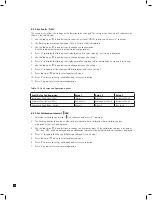
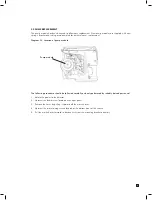
Страница 43: ...le The following procedure should be followed carefully and only performed by suitably trained personnel 1 Isolate the power to the detector 2 Unscrew the thumbscrew located on the front panel 3 Remove the cover by pulling it forward off the main chassis 4 Unscrew the two retaining screws located at the bottom front of the chassis 5 Pull the main chassis forward to disconnect it from the mounting ...

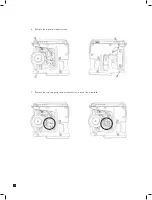
Страница 44: ...44 6 Remove the 4 pump module screws 7 Remove the two fixing clips and disconnect the tubes at the manifold ...

Страница 45: ...45 8 Slide the pump module out and disconnect the connector from the pcb 9 Fit the new pump module following the steps above in reverse order ...

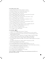
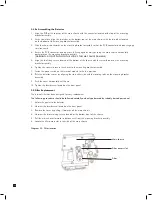
Страница 46: ... screws to secure the chassis to the mounting bracket assembly 7 Switch the power switch on the terminal module to the on position 8 Refit the detector s cover by aligning the slots either side with the locating tabs on the mounting bracket assembly 9 Push the cover horizontally until home 10 Tighten the thumbscrew located on the front panel 9 4 Filter Replacement The internal filter has been desi...

Страница 47: ...measured by the sensor cartridge and the concentration displayed as the equivalent reading in ppm NF3 Contact Zellweger Analytics for the availability of other detectable gases using the pyrolyzer module Filter connector Manifold ports New filter correct orientation Diagram 32 Pyrolyzer module attached to MIDAS gas detector MIDAS gas detector Pyrolyzer module MIDAS T 00P WARNING To maintain stated...

Страница 48: ...s in the bottom of the mounting bracket 7 Plug the connector into the socket con5 at the bottom left of the terminal board Diagram 33 Connecting the Pyrolyzer module 8 Offer the pyrolyzer module up underneath the mounting bracket ensuring that the fitting at the top rear of the pyrolyzer mates with the sample inlet port at the bottom of the mounting bracket 9 Align the three screw mounting bosses ...

Страница 49: ... of the chassis with the screw threads on the mounting bracket assembly 6 Tighten the screws to secure the chassis to the mounting bracket assembly 7 Fit sensor cartridge MIDAS S HFX into the sensor cartridge chamber 8 Switch the power switch on the terminal module to the on position 9 Refit the detector s cover by aligning the slots either side with the locating tabs on the mounting bracket assem...

Страница 50: ...ntrols monitors and measures the gas sample flow and signals any fault conditions to the user via the LCD screen e g due to flow problems caused by pump failure or failure of the pyrolyzer unit etc Diagram 37 Pyrolyzer option flow diagram Pyrolyzer Gas Sensor Sample Inlet 500 ml min Pyrolyzer Flow rate 50 ml min Voltage Current Sensing Driver Heater Heater Controller Pyrolyzer Option heater voltag...

Страница 51: ...n the local LCD trigger relays and provide a digital output via Modbus TCP Ethernet For full installation and wiring instructions please refer to the separate MIDAS Analog Input module Quick Start Guide MIDAS A 023 available on request from Zellweger Analytics 11 1 Fitting the Analog Module 1 Isolate the power to the detector 2 Unscrew the thumbscrew located on the front panel 3 Remove the cover b...

Страница 52: ...sly 4 Ensure the PCB connector and tubes are fully engaged by firmly pushing the main chassis horizontally backwards on the mounting bracket assembly WARNING DO NOT PUSH ON THE LCD AS THIS MAY CAUSE DAMAGE 5 Align the two fixing screws located at the bottom of the chassis with the screw threads on the mounting bracket assembly 6 Tighten the screws to secure the chassis to the mounting bracket asse...

Страница 53: ...ce cartridge F41 BaseLine fault Sensor baseline has drifted Check for background gas concentration temperature or humidity fluctuations Perform zero calibration Replace cartridge F42 Calibration expired Too long since last calibration Replace or calibrate the cartridge F43 Cartridge expired Cartridge is too old Replace cartridge F44 Cell failure Cartridge has failed Reflex check Replace cartridge ...

Страница 54: ...it is possible to connect hundreds of MIDAS units to an Ethernet network which is part of the end user s process LAN and more information may be required from the local IT department and Zellweger Analytics as appropriate 14 1 Physical Network Components The Ethernet 100BaseT physical network is intended to connect computers to other computers through hubs For this reason a MIDAS cannot communicat...

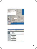
Страница 55: ...55 Diagram 40 IP Address setting in Windows XP Diagram 41 Sample MIDAS web page ...

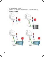
Страница 56: ...56 15 TYPICAL INSTALLATION TOPOLOGIES MIDAS has very flexible installation options to allow the user to select the one most suitable for their specific application 15 1 Conventional Installation ...

Страница 57: ...57 15 2 Modbus TCP Installation 15 3 Power over Ethernet POE Installation ...

Страница 58: ...yzer module that operates with and universal MIDAS Extractive Transmitter order separately and 1 Freon in line filter Units are powered via direct connection to transmitter unit Consult ZA for additional gases that may become available via pyrolysis Pyrolyzer includes Pyrolyzer Quick Start Guide and installation screws Order the NF3 cartridge MIDAS S HFX separately MIDAS T 00P 16 3 MIDAS Analog IN...

Страница 59: ...Dichlorosilane 0 8 ppm MIDAS S HCL Disilane 0 20 ppm MIDAS S SHX Fluorine 0 4 ppm MIDAS S HAL Germane 0 0 8 ppm MIDAS S HYD Hydrogen 0 1000 ppm MIDAS S H2X Hydrogen 0 100 LEL 1 MIDAS S LEL Hydrogen Bromide 0 8 ppm MIDAS S HCL Hydrogen Chloride 0 8 ppm MIDAS S HCL Hydrogen Cyanide 0 20 ppm MIDAS S HCN Hydrogen Fluoride 0 12 ppm MIDAS S HFX Hydrogen Selenide 0 0 4 ppm MIDAS S HSE Hydrogen Sulfide 0 ...

Страница 60: ...L Disilane 0 20 ppm MIDAS E SHX Fluorine 0 4 ppm MIDAS E HAL Germane 0 0 8 ppm MIDAS E HYD Hydrogen 0 1000 ppm MIDAS E H2X Hydrogen 0 100 LEL 1 MIDAS E LEL Hydrogen Bromide 0 8 ppm MIDAS E HCL Hydrogen Chloride 0 8 ppm MIDAS E HCL Hydrogen Cyanide 0 20 ppm MIDAS E HCN Hydrogen Fluoride 0 12 ppm MIDAS E HFX Hydrogen Selenide 0 0 4 ppm MIDAS E HSE Hydrogen Sulfide 0 40 ppm MIDAS E H2S Methane 0 100 ...

Страница 61: ... Hydrogen Sulfide 0 40 ppm kit MIDAS K H2S Nitric Oxide 0 100 ppm kit MIDAS K NOX Nitrogen Dioxide 0 12 ppm kit MIDAS K NO2 Oxygen 0 25 v v kit MIDAS K O2X Ozone 0 0 4 ppm kit MIDAS K O3X Phosphine 0 1 2 ppm kit MIDAS K PH3 Phosphorous Oxychloride 0 0 8 ppm kit MIDAS K POC Silane 0 20 ppm and Disilane 0 20 ppm kit MIDAS K SHX Silane low level 0 2 ppm kit MIDAS K SHL Sulfur Tetrafluoride 0 0 8 ppm ...

Страница 62: ...ernet PoE Service Port RS232C PPP protocol Certification Specification European CE Marked for sale in European Community Meets EN 50270 1999 Type 2 and EN55011 2000 Environmental ETL approved UL61010B 1 and CSA C22 2 No 1010 1 92 Performance Designed to meet UL2075 pending 2004 Electrical IEEE 802 3af 2003 Response Times Typically Toxic T90 30 seconds Catalytic T90 10 seconds Transport System Flow...

Страница 63: ...sure that the correct materials for an extractive application are obtained from reputable suppliers and are of proven quality and composition Inappropriate calibration equipment will lead to under or over presenting the wrong concentration of gas to the sensor cartridge during the calibration period Likewise contaminated or inadequately flushed tubing and other gas wet surfaces can also introduce ...

Страница 64: ...Hydrogen Hydrogen ppm H2 0 1000 ppm MIDAS S H2X Hydrogen Hydrogen Hydrogen Bromide HBr 0 8 0 ppm MIDAS S HCL Hydrogen Chloride Chlorine Hydrogen Chloride HCl 0 8 0 ppm MIDAS S HCL Hydrogen Chloride Chlorine Hydrogen Cyanide HCN 0 20 ppm MIDAS S HCN Hydrogen Cyanide Carbon Monoxide Hydrogen Fluoride HF 0 12 ppm MIDAS S HFX Hydrogen Fluoride Chlorine Hydrogen Selenide H2 Se 0 0 4 ppm MIDAS S HSE Sil...

Страница 65: ...lined tube has to be used response times may be longer than expected especially when using chlorine In this case it is especially important to keep the tubing short The pyrolyzer should be tested in the same way as an extractive system but using NF3 as the test gas If NF3 is not available chlorine can be used at a concentration of 5 ppm If using chlorine the freon filter must be removed from the u...

Страница 66: ...n Sulfide 25 500 120 Sulfur Dioxide SO2 MIDAS S SO2 8 Sulfur Dioxide 8 500 120 Sulfur Tetrafluoride SF4 MIDAS S SF4 0 8 Chlorine Low 500 120 TEOS TEOS MIDAS S TEO 40 Carbon Monoxide 100 500 120 Tungsten Tetrafluoride WF6 MIDAS S HFX 12 Chlorine 5 500 120 Notes 1 If Phosphine is not available Hydrogen Sulfide can be used to test these sensors Use a concentration of 2 ppm Important this should only ...

Страница 67: ...ly to the sensor cartridges limited as indicated below During this period Zellweger Analytics will repair or replace defective parts on an exchange basis F O B to approved service centers on a global basis This warranty does not cover damage caused by accident abuse abnormal operating conditions or extreme poisoning of the sensor cartridge Defective goods must be returned by the Buyer at the Buyer...

Страница 68: ...d in the instrument operation manual including prompt replacement or repair of defective parts and such other necessary calibration maintenance and repair as may be required in the reasonable judgment of Zellweger Analytics Normal wear and tear and parts damaged by abuse misuse negligence or accidents are specifically excluded from the warranty Purchaser acknowledges that notwithstanding any contr...

Страница 69: ...el Cancel Accept Top Level Accept Check Up Down Cancel X Monitor Reset Alarms and Faults 2 Sec Hold Additional Button Functions Setup Mode Up Accept Calibration Mode Accept Test Mode Enter Passcode Up 1 Sec With Passcode Down 1 Sec With Passcode Cancel Accept With Correct Passcode Accept With Incorrect Passcode Test Inhibit Enter Passcode Cancel Accept With Correct Passcode Accept With Incorrect P...

Страница 70: ... Review Network Function Selection Show Date Time Down Review Date Time Accept Monitoring Status Function Selection Show Event Log Accept Review Event Log Up Down Cancel Cancel Down Up Cancel Function Selection Show Gas Cal Up Down Up Cancel Accept Review Alarm Accept Review Fault Accept Review Gas Calibration Function Selection Show Software Info Down Up Accept Review Software Info Cancel ...

Страница 71: ...ction Show Gas Cal Show Last Gas Cal Month And Date Show Days To Next Gas Cal Show Last Gas Cal Year Accept Accept Accept Accept Show Alarm 1 Type Accept Accept Check Up Down Cancel X Review Returns to Normal Operation Monitoring Goes to next Function Selection state See Review state chart for Function Selection sequence Additional Button Functions Goes to previous Function Selection state See Rev...

Страница 72: ...pt Accept Show IP Address 3rd Digit Show IP Address 2nd Digit Accept Accept Show IP Address 4th Digit Accept Function Selection Show Date Time Show Time Show Month and Date Accept Accept Accept Show Year Accept Accept Check Up Down Cancel X Review Returns to Normal Operation Monitoring Goes to next Function Selection state See Review state chart for Function Selection sequence Additional Button Fu...

Страница 73: ...west event 2 Maximum number of events is 7 3 At Function Selection Show Event Log the dots from the flow meter show the number of events available 4 When showing event data the dots from the flow meter show the index of the current event Accept Check Up Down Cancel X Review Returns to Normal Operation Monitoring Goes to next Function Selection state See Review state chart for Function Selection se...

Страница 74: ...p Network Accept Cancel Cancel Function Selection Set Gas Calibration Down Up Cancel Function Selection Set Date Time Setup Date Time Accept Down Up Cancel Accept Setup Alarm Accept Setup Fault Accept Setup Gas Calibration Accept Check Up Down Cancel X Setup When at Function Selection 1 second hold goes to Function Selection Zero Gas Calibration in Calibration When at Function Selection 1 second h...

Страница 75: ...t Accept Accept Cancel Cancel Set Alarm Delay Accept Function Selection Set Gas Calibration Set Gas Calibration Period Cancel Accept Accept Set Alarm 1 Type Cancel Accept Cancel Accept Check Up Down Cancel X Setup Save new set of values if last step in sequence Abort changes When setting value increments or toggle value 1 second hold for faster increment When setting value decrements or toggle val...

Страница 76: ...dress 2nd Digit Accept Accept Cancel Set IP Address 4th Digit Accept Cancel Cancel Cancel Accept Auto Function Selection Set Date Time Set Minutes Set Hours Accept Accept Cancel Cancel Accept Set Year Set Date Format Accept Cancel Cancel Accept Set Month Set Date Accept Accept Cancel Cancel Accept Check Up Down Cancel X Setup Save new set of values if last step in sequence Abort changes When setti...

Страница 77: ...epeat Passcode 2nd Digit Repeat Passcode 1st Digit Accept Accept Cancel Accept Set Passcode 4th Digit Set Passcode 3rd Digit Accept Accept Cancel Cancel Cancel Accept Check Up Down Cancel X Setup Saves new passcode after last entry if the two entered passcodes are the same Abort changes When setting value increments value 1 second hold for faster increment When setting value decrements value 1 sec...

Страница 78: ...n at Function Selection 1 second hold goes to Function Selection Bump Test in Test When at Function Selection 1 second hold goes to Function Selection Set Alarm in Setup Additional Button Functions Function Selection 4 20 mA Calibration Function Selection Flow Calibration Down Up Down Up Accept Calibration 4 20 mA Calibration Accept Calibration Span Gas Calibration Accept Calibration Zero Gas Cali...

Страница 79: ... Full Scale Zero Gas Range 10 of Full Scale Span Gas Range Target Conc 20 of Full Scale Stable Time Required For Calibration Success 15 seconds Calibration Timeout 60 seconds Gas Calibration Result Codes PASS Successful Calibration FL 0H Zero Calibration Timeout Over Range FL 0L Zero Calibration Timeout Under Range FL 0U Zero Calibration Timeout Unstable FL SH Span Calibration Timeout Over Range F...

Страница 80: ...on flow slider When entering flow decrements value 1 second hold for faster decrement Additional Button Functions Accept Accept Accept Accept After A D Readings are completed After A D Readings are completed Cancel Cancel Cancel Cancel Cancel Cancel Notes 1 Setpoint 1 values Target Flow 350 cc min Minimum Flow 300 cc min Maximum Flow 400 cc min 2 Setpoint 2 values Target Flow 650 cc min Minimum Fl...

Страница 81: ... changes When adjusting increases output level 1 second hold for continuous increase When adjusting decreases output level 1 second hold for continuous decrease Additional Button Functions Saves new calibration values after last adjustment Function Selection 4 20 mA Calibration Adjust 4 mA Adjust 20 mA Cancel Accept Accept Cancel Accept ...

Страница 82: ...tion 1 second hold goes to Function Selection Set Alarm in Setup When at Function Selection 1 second hold goes to Function Selection Zero Gas Calibration in Calibration Additional Button Functions Function Selection Alarm Fault Simulation Down Up Down Up Accept Test Bump Test Accept Test Alarm Fault Simulation Cancel Function Selection Inhibit Accept Test Inhibit Down Up ...

Страница 83: ... Fault Simulation Request Alarm 1 Simulation Cancel Accept Request Alarm 2 Simulation Request Fault Simulation Confirm Alarm 1 Simulation Confirm Alarm 2 Simulation Confirm Fault Simulation Alarm 1 Simulation Active Alarm 2 Simulation Active Fault Simulation Active Cancel Cancel Accept Accept Cancel Cancel Accept Accept Cancel Cancel Accept Accept Cancel Cancel Down Up Down Up Down Up ...

Страница 84: ...itoring Status Accept if Inhibit Level not set to None Accept if entered directly from Monitoring Status Accept if entered from Test Menu Accept if entered directly from Monitoring Status and Inhibit Level set to None Accept if entered from Test Menu and Inhibit Level set to None Start here if entered directly from Monitoring Status The inhibit levels are a None no functions are inhibited b Alarms...

Страница 85: ...ency after hours Service call 1 847 634 2840 PLEASE NOTE While every effort has been made to ensure accuracy in this publication no responsibility can be accepted for errors or omissions Data may change as well as legislation and you are strongly advised to obtain copies of the most recently issued regulations standards and guidelines This publication is not intended to form the basis of a contrac...

Отзывы: