


7 - 56
7.9.1.3
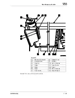
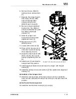
Roll-up Cover Assembly and Installation
Cover Assembly:
1. Attach the new cover to the roller.
-
Use extreme CAUTION when performing Step 2, since this step
spring loads the roll-up mechanism.
2. Roll up the new cover by the same number turns used to unroll the old
cover off the roller.
3. Tighten the locking screw [2].
4. Measure the amount of cover extending beyond the roller.
-
It should extend approximately the same distance measured in
Step 2 in the preceding procedure “To Disassemble the Cover”.
5. Attach the bracket [9] to the free end of the cover. Seven (M4x10)
screws [10].
6. Rewrap the tensioner cable [4] around the roller [5] by the same
number of wraps recorded in Step 3 in the preceding procedure “To
Disassemble the Cover”.
Installing the Cover Assembly:
1. Place the cover assembly into position on the machine.
2. Attach the housing [3] to the side frame work [1]. Seven (M5x12)
screws, (M5) flat washers, and (M5) lock washers.
3. Slide the cover [12] through its two guides [7] and [11].
4. Attach the bracket [9] to the saddle cover [8]. Three (M5x8mm)
screws.
-
It may be necessary to temporarily loosen locking screw [2] to
extend the cover for attachment to the saddle cover [8]. If this is
necessary, use extreme CAUTION since the roller mechanism is
now spring loaded.
5. Connect the tensioner cables [4] and adjust tension if necessary, see
6. Install the bracket [14], with the wiper [6] attached. Four (M5x8)
screws.
7. Loosen the locking screw [2].
8. Start the machine.
9. In a Manual mode, at a slow traverse rate, position the X axis back and
forth while observing the roll-up and extension action of both covers.
Содержание V55
Страница 6: ...vi...
Страница 32: ...1 24 NOTES SKETCHES...
Страница 37: ...4V2A1563 E 2 3 FIGURE 2 1 SPINDLE POWER AND TORQUE CHARACTERISTICS...
Страница 39: ...4V2A1563 E 2 5 FIGURE 2 2 AXIS CONFIGURATION TRAVEL AND WORK CUBE...
Страница 41: ...4V2A1563 E 2 7 FIGURE 2 4 WORKPIECE SIZE LIMITATIONS...
Страница 53: ...4V2A1563 E 2 19 FIGURE 2 6 FLOOR SPACE FOR STANDARD MACHINE...
Страница 58: ...2 24 F IGURE 2 7 V55 WITH 25 TOOL ATC...
Страница 59: ...4V2A1563 E 2 25 F IGURE 2 8 V55 WITH 25 TOOL ATC AND LIFT UP CHIP CONVEYOR LEFT...
Страница 60: ...2 26 F IGURE 2 9 V55 WITH 25 TOOL ATC AND LIFT UP CHIP CONVEYOR RIGHT...
Страница 61: ...4V2A1563 E 2 27 F IGURE 2 10 V55 WITH 25 TOOL ATC LIFT UP CHIP CONVEYOR LEFT AND APC...
Страница 62: ...2 28 F IGURE 2 11 V55 WITH 25 TOOL ATC LIFT UP CHIP CONVEYOR RIGHT AND APC...
Страница 63: ...4V2A1563 E 2 29 F IGURE 2 12 V55 WITH 40 OR 80 TOOL ATC...
Страница 64: ...2 30 F IGURE 2 13 V55 WITH 40 OR 80 TOOL ATC AND LIFT UP CHIP CONVEYOR LEFT...
Страница 65: ...4V2A1563 E 2 31 F IGURE 2 14 V55 WITH 40 OR 80 TOOL ATC AND LIFT UP CHIP CONVEYOR RIGHT...
Страница 66: ...2 32 F IGURE 2 15 V55 WITH 40 OR 80 TOOL ATC LIFT UP CHIP CONVEYOR LEFT AND APC...
Страница 67: ...4V2A1563 E 2 33 F IGURE 2 16 V55 WITH 40 OR 80 TOOL ATC LIFT UP CHIP CONVEYOR RIGHT AND APC...
Страница 68: ...2 34 NOTES SKETCHES...
Страница 93: ...4V2A1563 E 3 23 FIGURE 3 6 LEVELING BASE POSITIONS AND BED TO FLOOR CLEARANCE...
Страница 94: ...3 24 NOTES SKETCHES...
Страница 99: ...4V2A1563 E 4 3 FIGURE 4 1 MACHINE CORE ELEMENTS...
Страница 103: ...4V2A1563 E 4 7 FIGURE 4 3 MAKINO PROFESSIONAL 3 CONTROL WITH MPC5...
Страница 106: ...4 10 NOTES SKETCHES...
Страница 114: ...4 18 NOTES SKETCHES...
Страница 123: ...4V2A1563 E 5 5 FIGURE 5 1 BASIC TROUBLESHOOTING FLOW CHART...
Страница 124: ...5 6 NOTES SKETCHES...
Страница 143: ...4V2A1563 E 5 25 NOTES SKETCHES...
Страница 153: ...4V2A1563 E 5 35 NOTES SKETCHES...
Страница 159: ...4V2A1563 E 5 41 NOTES SKETCHES...
Страница 166: ...5 48 NOTES SKETCHES...
Страница 191: ...4V2A1563 E 5 73 TEC F IGURE 5 26 S CHEMATIC PAGE FORMAT...
Страница 197: ...4V2A1563 E 5 79 NOTES SKETCHES...
Страница 198: ...5 80 NOTES SKETCHES...
Страница 202: ...NOTES SKETCHES...
Страница 227: ...4V2A1563 E 6 25 NOTES SKETCHES...
Страница 252: ...6 50 NOTES SKETCHES...
Страница 261: ...4V2A1563 E 6 59 FIGURE 6 36 SPINDLE HYDRAULIC CIRCUIT...
Страница 267: ...4V2A1563 E 6 65 FIGURE 6 40 L PORT SPINDLE LUBRICATION...
Страница 269: ...4V2A1563 E 6 67 FIGURE 6 41 V PORT SPINDLE LUBRICATION...
Страница 277: ...4V2A1563 E 6 75 NOTES SKETCHES...
Страница 279: ...4V2A1563 E 6 77 FIGURE 6 48 SEALING ROD INSTALLATION...
Страница 284: ...6 82 NOTES SKETCHES...
Страница 293: ...4V2A1563 E 7 5 F IGURE 7 3 AXIS DRIVE CIRCUIT...
Страница 297: ...4V2A1563 E 7 9 NOTES SKETCHES...
Страница 309: ...4V2A1563 E 7 21 FIGURE 7 12 BALL SCREW COOLING OIL AND TAC BEARING LUBRICATION PIPING...
Страница 311: ...4V2A1563 E 7 23 NOTES SKETCHES...
Страница 317: ...4V2A1563 E 7 29 FIGURE 7 18 BALL SCREW PRE TENSION PROCEDURE...
Страница 331: ...4V2A1563 E 7 43 FIGURE 7 26 Y AXIS LIMIT SWITCH TO DOG SETTINGS FIGURE 7 27 Z AXIS LIMIT SWITCH TO DOG SETTINGS...
Страница 346: ...7 58 NOTES SKETCHES...
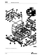
Страница 348: ...7 60 FIGURE 7 35 Y AXIS COVER SYSTEM...
Страница 351: ...4V2A1563 E 7 63 NOTES SKETCHES...
Страница 369: ...4V2A1563 E 7 81 NOTES SKETCHES...
Страница 370: ...7 82 NOTES SKETCHES...
Страница 374: ...NOTES SKETCHES...
Страница 386: ...8 12 NOTES SKETCHES...
Страница 403: ...4V2A1563 E 8 29 NOTES SKETCHES...
Страница 423: ...4V2A1563 E 8 49 NOTES SKETCHES...
Страница 432: ...8 58 NOTES SKETCHES...
Страница 439: ...4V2A1563 E 9 5 NOTES SKETCHES...
Страница 441: ...4V2A1563 E 9 7 F IGURE 9 3 OIL CONTROLLER ELECTRICAL DRAWINGS...
Страница 443: ...4V2A1563 E 9 9 FIGURE 9 4 OIL CONTROLLER MACHINE SYSTEM...
Страница 464: ...9 30 NOTES SKETCHES...
Страница 468: ...NOTES SKETCHES...
Страница 490: ...A 22 NOTES SKETCHES...
Страница 525: ...4V2A1563 E A 57 NOTES SKETCHES...
Страница 526: ...A 58 NOTES SKETCHES...
Страница 534: ...B 6 NOTES SKETCHES...
Страница 546: ...B 18 NOTES SKETCHES...
Страница 558: ...B 30 NOTES SKETCHES...
Страница 564: ...B 36 NOTES SKETCHES...
Страница 568: ...B 40 NOTES SKETCHES...


