


4V2A1563 (E)
6 - 15
#13 = 866.14 (MAX. INCH MOMENT);
Maximum inch tool moment (lb in.)
#15 = 100 (MAX. FORCE IN POUNDS);
Maximum side force in lb
N2 #14 = #9 * #3 * #19;
Calculate feedrate per minute
#101 = [#10 * #18 * #1 * #14 * #3] / #12;
Calculate force
#100 = #101 * #[2000 + #11];
Calculate tool moment
IF [#101 LT #15] GOTO3;
Compare calculated force to max. allowed
#3000 = 0 (FORCE TOO GREAT, SEE #101);
Alarm message
N3 IF [#100 LT #13] GOTO4;
Compare calculated moment to max. allowed
#3000 = 0 (MOMENT TOO GREAT, SEE
#100);
…
Alarm message
N1 #3000 = 0 (TOOL MOMENT COMMAND
ERROR);
…
Alarm message
N4 M99;
End of Macro
T
ABLE
6-8
FORCE
AND
MOMENT
MACRO
PROGRAM
(
CONTINUED
)
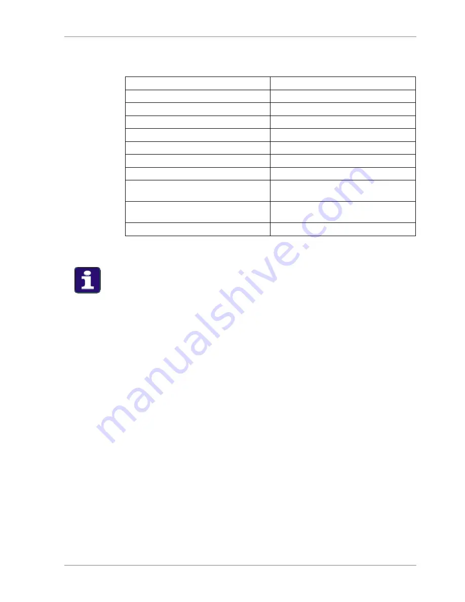
In Case of Alarm
If an alarm is issued by the Macro program for either force or tool moment, change the
cutting conditions (i.e. feedrate, spindle rpm, tool length, etc.) to reduce the value of
one or more variables then rerun the program.
Содержание V55
Страница 6: ...vi...
Страница 32: ...1 24 NOTES SKETCHES...
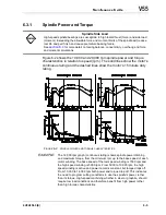
Страница 37: ...4V2A1563 E 2 3 FIGURE 2 1 SPINDLE POWER AND TORQUE CHARACTERISTICS...
Страница 39: ...4V2A1563 E 2 5 FIGURE 2 2 AXIS CONFIGURATION TRAVEL AND WORK CUBE...
Страница 41: ...4V2A1563 E 2 7 FIGURE 2 4 WORKPIECE SIZE LIMITATIONS...
Страница 53: ...4V2A1563 E 2 19 FIGURE 2 6 FLOOR SPACE FOR STANDARD MACHINE...
Страница 58: ...2 24 F IGURE 2 7 V55 WITH 25 TOOL ATC...
Страница 59: ...4V2A1563 E 2 25 F IGURE 2 8 V55 WITH 25 TOOL ATC AND LIFT UP CHIP CONVEYOR LEFT...
Страница 60: ...2 26 F IGURE 2 9 V55 WITH 25 TOOL ATC AND LIFT UP CHIP CONVEYOR RIGHT...
Страница 61: ...4V2A1563 E 2 27 F IGURE 2 10 V55 WITH 25 TOOL ATC LIFT UP CHIP CONVEYOR LEFT AND APC...
Страница 62: ...2 28 F IGURE 2 11 V55 WITH 25 TOOL ATC LIFT UP CHIP CONVEYOR RIGHT AND APC...
Страница 63: ...4V2A1563 E 2 29 F IGURE 2 12 V55 WITH 40 OR 80 TOOL ATC...
Страница 64: ...2 30 F IGURE 2 13 V55 WITH 40 OR 80 TOOL ATC AND LIFT UP CHIP CONVEYOR LEFT...
Страница 65: ...4V2A1563 E 2 31 F IGURE 2 14 V55 WITH 40 OR 80 TOOL ATC AND LIFT UP CHIP CONVEYOR RIGHT...
Страница 66: ...2 32 F IGURE 2 15 V55 WITH 40 OR 80 TOOL ATC LIFT UP CHIP CONVEYOR LEFT AND APC...
Страница 67: ...4V2A1563 E 2 33 F IGURE 2 16 V55 WITH 40 OR 80 TOOL ATC LIFT UP CHIP CONVEYOR RIGHT AND APC...
Страница 68: ...2 34 NOTES SKETCHES...
Страница 93: ...4V2A1563 E 3 23 FIGURE 3 6 LEVELING BASE POSITIONS AND BED TO FLOOR CLEARANCE...
Страница 94: ...3 24 NOTES SKETCHES...
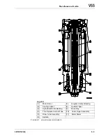
Страница 99: ...4V2A1563 E 4 3 FIGURE 4 1 MACHINE CORE ELEMENTS...
Страница 103: ...4V2A1563 E 4 7 FIGURE 4 3 MAKINO PROFESSIONAL 3 CONTROL WITH MPC5...
Страница 106: ...4 10 NOTES SKETCHES...
Страница 114: ...4 18 NOTES SKETCHES...
Страница 123: ...4V2A1563 E 5 5 FIGURE 5 1 BASIC TROUBLESHOOTING FLOW CHART...
Страница 124: ...5 6 NOTES SKETCHES...
Страница 143: ...4V2A1563 E 5 25 NOTES SKETCHES...
Страница 153: ...4V2A1563 E 5 35 NOTES SKETCHES...
Страница 159: ...4V2A1563 E 5 41 NOTES SKETCHES...
Страница 166: ...5 48 NOTES SKETCHES...
Страница 191: ...4V2A1563 E 5 73 TEC F IGURE 5 26 S CHEMATIC PAGE FORMAT...
Страница 197: ...4V2A1563 E 5 79 NOTES SKETCHES...
Страница 198: ...5 80 NOTES SKETCHES...
Страница 202: ...NOTES SKETCHES...
Страница 227: ...4V2A1563 E 6 25 NOTES SKETCHES...
Страница 252: ...6 50 NOTES SKETCHES...
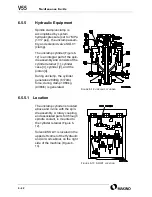
Страница 261: ...4V2A1563 E 6 59 FIGURE 6 36 SPINDLE HYDRAULIC CIRCUIT...
Страница 267: ...4V2A1563 E 6 65 FIGURE 6 40 L PORT SPINDLE LUBRICATION...
Страница 269: ...4V2A1563 E 6 67 FIGURE 6 41 V PORT SPINDLE LUBRICATION...
Страница 277: ...4V2A1563 E 6 75 NOTES SKETCHES...
Страница 279: ...4V2A1563 E 6 77 FIGURE 6 48 SEALING ROD INSTALLATION...
Страница 284: ...6 82 NOTES SKETCHES...
Страница 293: ...4V2A1563 E 7 5 F IGURE 7 3 AXIS DRIVE CIRCUIT...
Страница 297: ...4V2A1563 E 7 9 NOTES SKETCHES...
Страница 309: ...4V2A1563 E 7 21 FIGURE 7 12 BALL SCREW COOLING OIL AND TAC BEARING LUBRICATION PIPING...
Страница 311: ...4V2A1563 E 7 23 NOTES SKETCHES...
Страница 317: ...4V2A1563 E 7 29 FIGURE 7 18 BALL SCREW PRE TENSION PROCEDURE...
Страница 331: ...4V2A1563 E 7 43 FIGURE 7 26 Y AXIS LIMIT SWITCH TO DOG SETTINGS FIGURE 7 27 Z AXIS LIMIT SWITCH TO DOG SETTINGS...
Страница 346: ...7 58 NOTES SKETCHES...
Страница 348: ...7 60 FIGURE 7 35 Y AXIS COVER SYSTEM...
Страница 351: ...4V2A1563 E 7 63 NOTES SKETCHES...
Страница 369: ...4V2A1563 E 7 81 NOTES SKETCHES...
Страница 370: ...7 82 NOTES SKETCHES...
Страница 374: ...NOTES SKETCHES...
Страница 386: ...8 12 NOTES SKETCHES...
Страница 403: ...4V2A1563 E 8 29 NOTES SKETCHES...
Страница 423: ...4V2A1563 E 8 49 NOTES SKETCHES...
Страница 432: ...8 58 NOTES SKETCHES...
Страница 439: ...4V2A1563 E 9 5 NOTES SKETCHES...
Страница 441: ...4V2A1563 E 9 7 F IGURE 9 3 OIL CONTROLLER ELECTRICAL DRAWINGS...
Страница 443: ...4V2A1563 E 9 9 FIGURE 9 4 OIL CONTROLLER MACHINE SYSTEM...
Страница 464: ...9 30 NOTES SKETCHES...
Страница 468: ...NOTES SKETCHES...
Страница 490: ...A 22 NOTES SKETCHES...
Страница 525: ...4V2A1563 E A 57 NOTES SKETCHES...
Страница 526: ...A 58 NOTES SKETCHES...
Страница 534: ...B 6 NOTES SKETCHES...
Страница 546: ...B 18 NOTES SKETCHES...
Страница 558: ...B 30 NOTES SKETCHES...
Страница 564: ...B 36 NOTES SKETCHES...
Страница 568: ...B 40 NOTES SKETCHES...


