


5 - 60
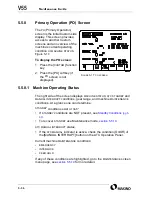
5.5.10.2 Maintenance Mode
The Maintenance mode provides
access to ATC, ATC magazine
“automatic” operations. Mainte-
nance mode allows step-by-step
control of ATC related operations.
•
This function is useful for
setup, adjustment and
alignment of ATC components,
and recovery of an interrupted
automatic action.
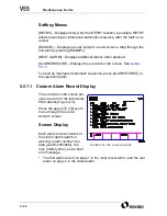
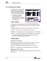
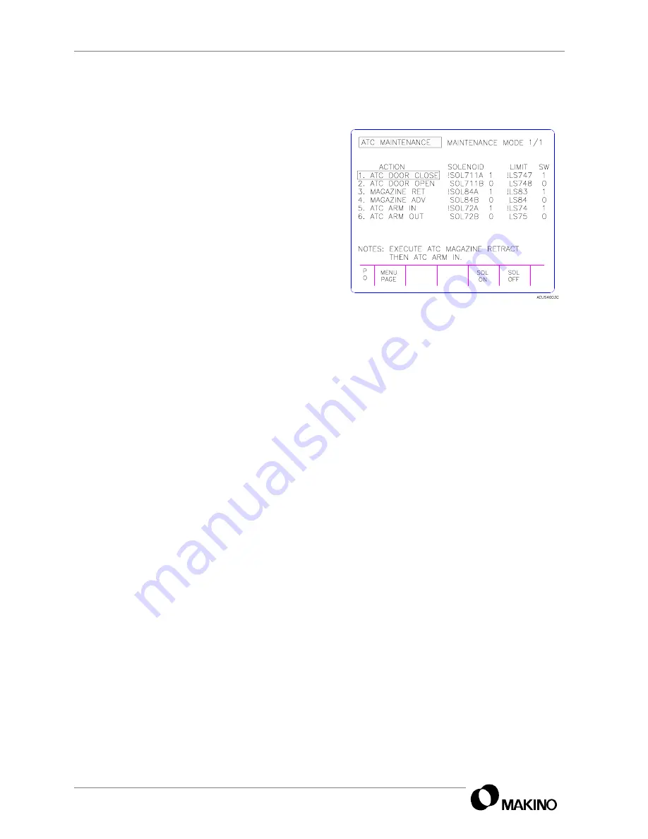
Screen Display
The following items are displayed on the ATC MAINTENANCE screen.
(Actual screen content (action steps) varies based on the ATC (option)
provided.)
MAINTENANCE MODE – Indicates the Maintenance mode is active.
ACTION – Lists steps of ATC motion (based on ATC type).
SOLENOID – Lists solenoid and current output status (1= On and 0=Off).
LIMIT SW – Lists limit switch and current input status (1= On and 0=Off).
•
SOL and LS designations preceded by and exclamation mark (!)
indicate the conditions needed for
STANDBY
.
Softkey Menus
Maintenance mode active:
[MENU PAGE] – Displays to the maintenance
MENU
page to activate/
deactivate Maintenance mode or return to the PO screen.
[SOL ON] – Energizes the solenoid related to the selected action.
[SOL OFF] – Deenergizes the solenoid related to the selected item.
Maintenance mode inactive
[MENU PAGE] – to activate/deactivate Maintenance mode or return to the
PO screen.
F
IGURE
5-19
ATC
MAINTENANCE
SCREEN
Содержание V55
Страница 6: ...vi...
Страница 32: ...1 24 NOTES SKETCHES...
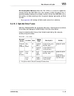
Страница 37: ...4V2A1563 E 2 3 FIGURE 2 1 SPINDLE POWER AND TORQUE CHARACTERISTICS...
Страница 39: ...4V2A1563 E 2 5 FIGURE 2 2 AXIS CONFIGURATION TRAVEL AND WORK CUBE...
Страница 41: ...4V2A1563 E 2 7 FIGURE 2 4 WORKPIECE SIZE LIMITATIONS...
Страница 53: ...4V2A1563 E 2 19 FIGURE 2 6 FLOOR SPACE FOR STANDARD MACHINE...
Страница 58: ...2 24 F IGURE 2 7 V55 WITH 25 TOOL ATC...
Страница 59: ...4V2A1563 E 2 25 F IGURE 2 8 V55 WITH 25 TOOL ATC AND LIFT UP CHIP CONVEYOR LEFT...
Страница 60: ...2 26 F IGURE 2 9 V55 WITH 25 TOOL ATC AND LIFT UP CHIP CONVEYOR RIGHT...
Страница 61: ...4V2A1563 E 2 27 F IGURE 2 10 V55 WITH 25 TOOL ATC LIFT UP CHIP CONVEYOR LEFT AND APC...
Страница 62: ...2 28 F IGURE 2 11 V55 WITH 25 TOOL ATC LIFT UP CHIP CONVEYOR RIGHT AND APC...
Страница 63: ...4V2A1563 E 2 29 F IGURE 2 12 V55 WITH 40 OR 80 TOOL ATC...
Страница 64: ...2 30 F IGURE 2 13 V55 WITH 40 OR 80 TOOL ATC AND LIFT UP CHIP CONVEYOR LEFT...
Страница 65: ...4V2A1563 E 2 31 F IGURE 2 14 V55 WITH 40 OR 80 TOOL ATC AND LIFT UP CHIP CONVEYOR RIGHT...
Страница 66: ...2 32 F IGURE 2 15 V55 WITH 40 OR 80 TOOL ATC LIFT UP CHIP CONVEYOR LEFT AND APC...
Страница 67: ...4V2A1563 E 2 33 F IGURE 2 16 V55 WITH 40 OR 80 TOOL ATC LIFT UP CHIP CONVEYOR RIGHT AND APC...
Страница 68: ...2 34 NOTES SKETCHES...
Страница 93: ...4V2A1563 E 3 23 FIGURE 3 6 LEVELING BASE POSITIONS AND BED TO FLOOR CLEARANCE...
Страница 94: ...3 24 NOTES SKETCHES...
Страница 99: ...4V2A1563 E 4 3 FIGURE 4 1 MACHINE CORE ELEMENTS...
Страница 103: ...4V2A1563 E 4 7 FIGURE 4 3 MAKINO PROFESSIONAL 3 CONTROL WITH MPC5...
Страница 106: ...4 10 NOTES SKETCHES...
Страница 114: ...4 18 NOTES SKETCHES...
Страница 123: ...4V2A1563 E 5 5 FIGURE 5 1 BASIC TROUBLESHOOTING FLOW CHART...
Страница 124: ...5 6 NOTES SKETCHES...
Страница 143: ...4V2A1563 E 5 25 NOTES SKETCHES...
Страница 153: ...4V2A1563 E 5 35 NOTES SKETCHES...
Страница 159: ...4V2A1563 E 5 41 NOTES SKETCHES...
Страница 166: ...5 48 NOTES SKETCHES...
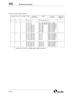
Страница 191: ...4V2A1563 E 5 73 TEC F IGURE 5 26 S CHEMATIC PAGE FORMAT...
Страница 197: ...4V2A1563 E 5 79 NOTES SKETCHES...
Страница 198: ...5 80 NOTES SKETCHES...
Страница 202: ...NOTES SKETCHES...
Страница 227: ...4V2A1563 E 6 25 NOTES SKETCHES...
Страница 252: ...6 50 NOTES SKETCHES...
Страница 261: ...4V2A1563 E 6 59 FIGURE 6 36 SPINDLE HYDRAULIC CIRCUIT...
Страница 267: ...4V2A1563 E 6 65 FIGURE 6 40 L PORT SPINDLE LUBRICATION...
Страница 269: ...4V2A1563 E 6 67 FIGURE 6 41 V PORT SPINDLE LUBRICATION...
Страница 277: ...4V2A1563 E 6 75 NOTES SKETCHES...
Страница 279: ...4V2A1563 E 6 77 FIGURE 6 48 SEALING ROD INSTALLATION...
Страница 284: ...6 82 NOTES SKETCHES...
Страница 293: ...4V2A1563 E 7 5 F IGURE 7 3 AXIS DRIVE CIRCUIT...
Страница 297: ...4V2A1563 E 7 9 NOTES SKETCHES...
Страница 309: ...4V2A1563 E 7 21 FIGURE 7 12 BALL SCREW COOLING OIL AND TAC BEARING LUBRICATION PIPING...
Страница 311: ...4V2A1563 E 7 23 NOTES SKETCHES...
Страница 317: ...4V2A1563 E 7 29 FIGURE 7 18 BALL SCREW PRE TENSION PROCEDURE...
Страница 331: ...4V2A1563 E 7 43 FIGURE 7 26 Y AXIS LIMIT SWITCH TO DOG SETTINGS FIGURE 7 27 Z AXIS LIMIT SWITCH TO DOG SETTINGS...
Страница 346: ...7 58 NOTES SKETCHES...
Страница 348: ...7 60 FIGURE 7 35 Y AXIS COVER SYSTEM...
Страница 351: ...4V2A1563 E 7 63 NOTES SKETCHES...
Страница 369: ...4V2A1563 E 7 81 NOTES SKETCHES...
Страница 370: ...7 82 NOTES SKETCHES...
Страница 374: ...NOTES SKETCHES...
Страница 386: ...8 12 NOTES SKETCHES...
Страница 403: ...4V2A1563 E 8 29 NOTES SKETCHES...
Страница 423: ...4V2A1563 E 8 49 NOTES SKETCHES...
Страница 432: ...8 58 NOTES SKETCHES...
Страница 439: ...4V2A1563 E 9 5 NOTES SKETCHES...
Страница 441: ...4V2A1563 E 9 7 F IGURE 9 3 OIL CONTROLLER ELECTRICAL DRAWINGS...
Страница 443: ...4V2A1563 E 9 9 FIGURE 9 4 OIL CONTROLLER MACHINE SYSTEM...
Страница 464: ...9 30 NOTES SKETCHES...
Страница 468: ...NOTES SKETCHES...
Страница 490: ...A 22 NOTES SKETCHES...
Страница 525: ...4V2A1563 E A 57 NOTES SKETCHES...
Страница 526: ...A 58 NOTES SKETCHES...
Страница 534: ...B 6 NOTES SKETCHES...
Страница 546: ...B 18 NOTES SKETCHES...
Страница 558: ...B 30 NOTES SKETCHES...
Страница 564: ...B 36 NOTES SKETCHES...
Страница 568: ...B 40 NOTES SKETCHES...


