background image


7 - 32

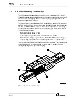
7.7.3

LM Guide Installation

All axes have two guide rails. The X and Y axes have two guide blocks per 
rail and the Z axis has three guide blocks per rail. The mounting character-
istic for each axis is defined below.

The X axis rails are stationary mounted to the top of the column and 
the blocks are mounted to the saddle. 

The Y axis rails are mounted to the bed and the blocks are mounted to 
the table. 

The Z axis rails are mounted to the front of the saddle and the blocks 
are mounted to the ram.

Each axis contains a “datum” and a “subsidiary”. The datum rail is aligned 
to ball screw centerline and the subsidiary rail aligned to the datum rail.

7.7.4

LM Guide Replacement

Makino uses “Precision Grade” guides which permits individual guide 
replacement (rather than sets). Also, the guides contain end, side, and 
inner seals to prevent contamination of the re-circulating balls.

Damage to the guide rails and blocks may occur in the event of a machine 
wreck. Makino recommends replacing the guide rail and block assembly if 
either component is damaged. Rail damage may not be apparent to the 
naked eye.

Guide Rail Replacement

Guide rail installation and replacement should be performed only be qualified person-
nel, since the installation process sets the proper preload for the guide rail blocks.

Содержание V55

Страница 1: ...Makino Customer Support Randy Ashley 1st Release Date April 1 1999 Revision s Date 1 Revision B 6 21 99 Typos and DI 4v 0865 Copyright 1999 Makino Inc All Rights Reserved No part of this manual may b...

Страница 2: ...ing hazardous condition with a high probability of death or severe injury Precautions must be taken immediately to prevent per sonal injury or death A WARNING icon proceeds each warning statement A WA...

Страница 3: ...o com Makino 7680 Innovation Way Mason Ohio 45040 USA Technical Support Services 888 Makino4 625 4664 Mon Fri 7 00 a m to 8 00 p m Sat 8 00 a m to 2 00 p m Eastern Standard Time Fax 513 459 1825 Parts...

Страница 4: ...savoir comment l utiliser sans danger et correctement afin d eviter tout accident HINWEIS Alle Personen die nur Teile des Handbuches oder kein Englisch verstenen m ssen sich dieses Handbuch erkl ren l...

Страница 5: ...hapter 3 Preventive Maintenance Chapter 4 Machine Tool System Overview Chapter 5 Troubleshooting Chapter 6 Spindle Head Unit Chapter 7 Feed Axis Unit Chapter 8 A25 ATC Automatic Tool Changer Unit Chap...

Страница 6: ...vi...

Страница 7: ...4V2A1563 E 01 4va Safety fm Makino V55 High speed Vertical Machining Center Chapter 1 Safety Precautions For a Safe Working Environment...

Страница 8: ...1 Slings 1 11 1 6 2 Chains 1 11 1 6 3 Hooks 1 12 1 6 4 Eye Bolts 1 12 1 6 5 Rings 1 12 1 6 6 Lifting the Machine or Components 1 13 1 6 7 Lifting Workpieces and Fixtures 1 13 1 7 Mechanical Maintenan...

Страница 9: ...d use 1 2 General Safety Safety precautions or requirements discussed in Makino guides or manu als do not supersede any safety requirements imposed by local state or federal governments All government...

Страница 10: ...machine contact your Makino service group for answers to any questions about safety and your Makino machine 1 2 1 Danger Warning Caution Statements and Symbols It is important that all employees recog...

Страница 11: ...YMBOL SHAPES AND THEIR MEANING Symbol Meaning A triangle or diamond shaped safety symbol indicates a hazard exists in the area or behind the enclosure where the symbol is placed The symbol at left ind...

Страница 12: ...d be safeguarded to the greatest extent possible for all machining operations In addition to panel locks interlocks and guarding certain areas of the machining center are color coded for safety It is...

Страница 13: ...out device All persons performing maintenance on the machine at the same time shall install their own padlock onto the lockout device 6 Disconnect the main power of all power sources i e electrical ai...

Страница 14: ...operly stored chemicals or flammable materials and any unusual fumes Loose worn or broken flooring Slippery broken or unstable platforms Missing broken or unstable handrails Avoid making sudden moveme...

Страница 15: ...operated maintained and equipped with complete regard for operator safety Only qualified personnel trained in safety and all machining center func tions should be allowed to operate maintain or repai...

Страница 16: ...mbers and range of movement which may create pinch points Always be cautious of these areas Avoid pinch points entirely during machine operation Keep the machining center properly maintained Perform m...

Страница 17: ...perate the machine with any safety device disabled or removed or any cover open or removed Do not allow yourself to become trapped or caught in pinch points Always be aware of a safe exit when in or a...

Страница 18: ...operations can safely be resumed Never step on machine covers as they can become slippery during normal operation and are not designed to support your weight Never perform grinding operations in the v...

Страница 19: ...dustry standards Any lifting device that cannot be repaired must be destroyed 1 6 1 Slings Use nylon slings when lifting irregular shape objects and Never exceed the lifting capacity of any sling Prot...

Страница 20: ...0 C 900 F Heat exposure can change the physical properties of the stock and create an unsafe eye bolt Never use an inch eye bolt in a metric thread or vice versa Use inch series thread eye bolts in in...

Страница 21: ...ly qualified riggers should perform machine lifting operations Never place any portion of your body beneath a suspended object Lift the machining center only at the designated lifting points Never lif...

Страница 22: ...disassembling any portion of their drive train Be familiar with and adhere to safe lifting practices described in section 1 6 before lifting the machine or components Never return the machining cente...

Страница 23: ...enance procedure within any electrical control cabinet Electrical Maintenance Equipment Use only industry standard approved electrical testing equipment Volt Ohm Meters Oscilloscopes Static Ground Wri...

Страница 24: ...ly halt all machine functions Descriptions operational detail and precautions related to these safety features are described in the Operation Guide 1 9 2 Location of Emergency Stop Buttons EMERGENCY b...

Страница 25: ...ry or death During machining keep Door Interlock FIGURE 1 1 SPLASH GUARD DOOR SAFETY LABEL AND OPERATION PANEL E STOP BUTTON before cycling ATC of tool can cause tool to be thrown during ATC cycle lea...

Страница 26: ...ent and parts can lead to FIGURE 1 3 SCRAPER CONVEYOR SAFETY LABEL AND MTC E STOP BUTTON MAKINO V55 tool can cause Stop spindle before working on or near rotating tool or Do not approach injury or dea...

Страница 27: ...speeds and feeds appropriate for cutting conditions and tooling limitations Use a glove or shop cloth and avoid the cutting edges when handling or changing tools You Should Never reach into the machi...

Страница 28: ...s recommendation Not all tools are designed for HSM and balancing alone will not make them safe for this application Confirm suitability for high speed application with the tool manufac turer Balance...

Страница 29: ...y when all machine motion is completely stopped and the control is in the STOP or RESET state Be careful not to slip on the tilted telescopic covers Remember injury can occur if the body is caught bet...

Страница 30: ...ces Use extreme care not to place fingers or hands where they may be pinched while loading or unloading a workpiece 1 12 Coolant Safety The V55 comes with several coolant options Follow these safety g...

Страница 31: ...ide prior to connecting power to the machining center 1 14 Required Reading Each person assigned to operate maintain or repair a machining center should first read the guide that is appropriate for th...

Страница 32: ...1 24 NOTES SKETCHES...

Страница 33: ...4V2A1563 E 02 4vb Specifications fm Makino V55 High speed Vertical Machining Center Chapter 2 Specifications Machine Unit and Control Specifications...

Страница 34: ...3 1 Control Panel 2 11 2 3 2 Custom Side Features 2 12 2 3 3 Machine Communications 2 13 2 3 4 Maintenance and Safety 2 14 2 3 5 Controlled Axes and Coordinate Systems 2 14 2 3 6 Programming 2 15 2 3...

Страница 35: ...or each machine unit are provided below These specifica tions are collected here to serve as a quick reference For more detail on unit design principle of operation and maintenance refer to the relate...

Страница 36: ...Speed Range 15 14 000 rpm Number of Speed Ranges Continuous with two step electric changeover Acceleration Time 0 8 sec at 7 000 rpm and 2 3 sec at 14 000 rpm Deceleration Time 0 7 sec at 7 000 rpm an...

Страница 37: ...4V2A1563 E 2 3 FIGURE 2 1 SPINDLE POWER AND TORQUE CHARACTERISTICS...

Страница 38: ...n environment and maintenance to be maintained or guaranteed TABLE 2 2 AXIS TRAVEL SPECIFICATION Item Specification approx US X Axis Travel Saddle 900 mm 35 4 Y Axis Travel Table 500 mm 19 7 Z Axis Tr...

Страница 39: ...4V2A1563 E 2 5 FIGURE 2 2 AXIS CONFIGURATION TRAVEL AND WORK CUBE...

Страница 40: ...BLE SPECIFICATIONS Item Specification approx US Table Dimensions L W 1 000 500 mm 39 37 19 7 T Slots Five 18 35 30 mm 0 71 1 38 1 18 Table Weight 70 kg 31 75 lb Height to Table Surface 980 mm 38 6 Wor...

Страница 41: ...4V2A1563 E 2 7 FIGURE 2 4 WORKPIECE SIZE LIMITATIONS...

Страница 42: ...ox US Tool Selection Method Fixed Address Indexing Tool Storage Capacity 25 Tools Armless Tool Shank 40T JIS B6339 or BT40 MAS403 Std HSK A 63 Option Type of Retention Knob 40P JIS B6339 or P40TI MAS4...

Страница 43: ...RE 2 5 AUTOMATIC TOOL CHANGER TOOLING LENGTH AND DIAMETER LIMITATIONS TABLE 2 6 SPINDLE OIL TEMPERATURE CONTROLLER SPECIFICATION Item Specification approx US Cooling Capacity 7270 8370 W 50 60 Hz Cool...

Страница 44: ...rox US Maximum Operating Pressure 7 MPa 1 015 2 psi Discharge Rate 20 24 L min 4 4 5 3 gal min Tank Capacity 10 L 2 2 gal Motor Capacity 2 2kW 2 95 hp TABLE 2 8 COOLANT UNIT SPECIFICATIONS Item Specif...

Страница 45: ...9 inch Color LCD Clock Function MDI Function Flexible Control Panel Run Hour and Parts Count Display Routine Functions Tool Call by 4 Digit T Command All Axis Automatic Reference Return Automatic Too...

Страница 46: ...bilities like improved processing of small NC data blocks SGI is especially effec tive for machining 3 D shapes of molds and dies involving continuous exe cution of minute blocks under 1mm 0 040 In ef...

Страница 47: ...The baud rate is affected by the transfer speed of the host computer Approximate conversion for CPS Characters Per Second is baud rate divided by 10 Shielded Cable Only signals subject to both high f...

Страница 48: ...eature Detail Controlled Axes Number of Axis 3 up to 5 axes optional Simultaneous Control 3 Coordinate Systems Absolute or Incremental G90 G91 Automatic Return to Reference Point Manual or program cod...

Страница 49: ...Point Programming Calculator type Decimal Point Input Editing Part program editing Background editing Program number search Sequence number search Address and word search Part program collation and s...

Страница 50: ...ail Operation Support Functions Label Skip Control In Out Single Block Program Stop M00 Optional Stop M01 Optional Block Skip forward slash Dry Run Machine Lock Z axis Feed Cancel Auxiliary Function L...

Страница 51: ...Look Ahead for GI motion control Unidirectional Positioning G50 Feature Detail Interpolation Rapid Positioning Manual and program code G00 Linear Interpolation Manual and program code G01 Circular In...

Страница 52: ...ion approx US Height 3 113 mm 122 6 Width 25 Tool ATC 2 800 mm 110 2 Width 40 or 80 Tool ATC 2 700 mm 106 3 Depth 3 140 mm 123 6 Weight including CNC unit 9 300 kg 20 503 lb Leveling Method 3 Point Su...

Страница 53: ...4V2A1563 E 2 19 FIGURE 2 6 FLOOR SPACE FOR STANDARD MACHINE...

Страница 54: ...ting when calculating machine electrical consumption Ensure the electrical service voltages meet all requirements 200 220 VAC 10 75 kVa 50 60 Hz and a proper earth ground 100 ohms or less is provided...

Страница 55: ...Power ON Make Connections only All connections and settings must be confirmed by a Makino service representative prior to applying power TABLE 2 11 TRANSFORMER SPECIFICATION Transformer Specification...

Страница 56: ...ining center s point of connection Add additional filters or water traps as required The air supply should be permanently piped when the final site is determined Table 2 12 lists air specifications fo...

Страница 57: ...us optional features are shown in the following figures Figure 2 7 pg 2 24 V55 with 25 Tool ATC Figure 2 8 pg 2 25 V55 with 25 Tool ATC and Lift Up Chip Conveyor Left Figure 2 9 pg 2 26 V55 with 25 To...

Страница 58: ...2 24 F IGURE 2 7 V55 WITH 25 TOOL ATC...

Страница 59: ...4V2A1563 E 2 25 F IGURE 2 8 V55 WITH 25 TOOL ATC AND LIFT UP CHIP CONVEYOR LEFT...

Страница 60: ...2 26 F IGURE 2 9 V55 WITH 25 TOOL ATC AND LIFT UP CHIP CONVEYOR RIGHT...

Страница 61: ...4V2A1563 E 2 27 F IGURE 2 10 V55 WITH 25 TOOL ATC LIFT UP CHIP CONVEYOR LEFT AND APC...

Страница 62: ...2 28 F IGURE 2 11 V55 WITH 25 TOOL ATC LIFT UP CHIP CONVEYOR RIGHT AND APC...

Страница 63: ...4V2A1563 E 2 29 F IGURE 2 12 V55 WITH 40 OR 80 TOOL ATC...

Страница 64: ...2 30 F IGURE 2 13 V55 WITH 40 OR 80 TOOL ATC AND LIFT UP CHIP CONVEYOR LEFT...

Страница 65: ...4V2A1563 E 2 31 F IGURE 2 14 V55 WITH 40 OR 80 TOOL ATC AND LIFT UP CHIP CONVEYOR RIGHT...

Страница 66: ...2 32 F IGURE 2 15 V55 WITH 40 OR 80 TOOL ATC LIFT UP CHIP CONVEYOR LEFT AND APC...

Страница 67: ...4V2A1563 E 2 33 F IGURE 2 16 V55 WITH 40 OR 80 TOOL ATC LIFT UP CHIP CONVEYOR RIGHT AND APC...

Страница 68: ...2 34 NOTES SKETCHES...

Страница 69: ...4V2A1563 E 03 4va Preventive Maintenance fm Makino V55 High speed Vertical Machining Center Chapter 3 Preventive Maintenance...

Страница 70: ...or Grease Lubricated Systems 3 4 3 2 3 Makino Recommended Lubricants 3 5 3 2 3 1 Automatic Lube 3 6 3 3 Lubrication Breakout Chart 3 7 3 4 Preventive Maintenance Schedule 3 10 3 4 1 Initial Checks 3 1...

Страница 71: ...gests imple menting a PM Preventive Maintenance program from day one of the machine installation Such a program not only assures that the machine is operating safely and at peak performance but also s...

Страница 72: ...a key factor in achieving these requirements 3 2 1 Oils The V55 components using lubricating oils include the Oil Controller and the Hydraulic System The Oil Controller uses Makino Spindle Luricant t...

Страница 73: ...Be sure that the replacement oil is of the same viscosity as the supplied oil Using oil of different viscosity affects the system running temperature load and pressure promoting wear and premature fa...

Страница 74: ...sts the Makino recommended greases for the V55 3 2 2 1 Guidelines for Grease Lubricated Systems Practice these guidelines with any grease type lubrication system Keep grease clean and free of contamin...

Страница 75: ...ts components Regular oil changes and cleaning of the reservoirs keeps lacquer build up to a minimum and reduces component failure TABLE 3 1 MAKINO RECOMMENDED LUBRICANTS Supply Point Lube Type Manufa...

Страница 76: ...s ball nuts and LM guides at specific intervals This unit uses a grease car tridge and is equipped with a limit switch to generate an alarm when the cartridge needs replaced Recommended Grease Cartrid...

Страница 77: ...3 7 3 3 Lubrication Breakout Chart Table 3 2 pg 3 8 provides detail for units requiring oil lubrication Use Fig ure 3 1 for the locations of related fill and drain ports FIGURE 3 1 LUBRICATION BREAKO...

Страница 78: ...OFF OIL Oil Controller See DETAIL A Figure 3 1 Inspection Point Sight glass on reservoir Oil Level Keep level full in sight glass Frequency Inspect daily add oil as necessary Check oil level with the...

Страница 79: ...nt of table Frequency Every 1000 hours 6 months of operation Quantity 40cc each ball nut Lubricant Kluber Isoflex NBU 15 grease Method See chapter 7 Y Axis LM Guides See DETAIL D Figure 3 1 Lubricatio...

Страница 80: ...d simultaneously as they are located in the same area Checks and adjustments listed in the PM schedule keep the machine tool at peak performance This eliminates many annoying and time consuming machin...

Страница 81: ...ths of operation that the initial break in of components occur possibly leading to problems such as contamination of oil supplies During this period the machine moves more than at any other time as th...

Страница 82: ...checks at the beginning of each shift These are simple visual checks performed in a few minutes Use the Daily Inspection chart Figure 3 4 mounted on the side of the machine as a guide to component lo...

Страница 83: ...e movement 3 Listen for air leaks Have leaks repaired immediately HYDRAULIC SYSTEM 1 Check the oil level of the reservoir Add as needed 2 Check system pressure Pressure should be 7MPa 1017 psi OIL CON...

Страница 84: ...s necessary 2 Clean the chip pan of chips MAIN AIR SUPPLY FR UNIT 1 Check air pressure Air pressure should be 0 5 MPa 70 psi AIR DRYER 1 The air temperature should be 50 C 122 F or less TABLE 3 3 DAIL...

Страница 85: ...CKS Weekly PM Checks Checked Action By Date GENERAL CHECKS 1 Perform all listed Daily checks OIL CONTROLLER 1 Perform all listed Daily checks 2 Clean the air filter MAIN AIR SUPPLY 1 Inspect incoming...

Страница 86: ...s ON 3 Press the TEST button on switch body Confirm Main Power switch trips and power indicator lamp turns Off 4 Turn Main Power switch to Off wait one minute and set to On CHIP SCRAPER 1 Check and ad...

Страница 87: ...uired X Y AND Z BALL NUTS 1 Lubricate the X Y and Z axes ball nuts See chapter 7 X Y AND Z LM GUIDES 1 Lubricate the X Y and Z axes LM Guides See chapter 7 MACHINE COVERS AND DOORS 1 Y axis telescopic...

Страница 88: ...MACHINE LEVEL AND ALIGNMENTS 1 Check machine level adjust as necessary 2 Check spindle to table squareness see chapter 6 MOTORS 1 Clean air intake on all air cooled motors 2 Lubricate all motors in a...

Страница 89: ...orm all listed Semi Annual checks 5 Inspect all covers cables and hoses for wear and proper working condition 6 Check operating voltages HYDRAULIC SYSTEM 1 Drain old oil clean reservoir refill with ne...

Страница 90: ...of all E Stop buttons Immediately replace a malfunctioning button ATC Door Verify operation of Safety Interlock switch Immediately replace a malfunctioning switch Rolling S G Guard Verify operation o...

Страница 91: ...an be performed with one or two levels Using two levels simplified the process by allowing both planes X and Y to be viewed simultaneously Before leveling the machining center verify your precision le...

Страница 92: ...ne is level Level the machine as follows 1 Place a precision level on the table parallel with the X axis plane and a second level parallel with the Y axis plane as shown in Figure 3 5 2 Loosen the set...

Страница 93: ...4V2A1563 E 3 23 FIGURE 3 6 LEVELING BASE POSITIONS AND BED TO FLOOR CLEARANCE...

Страница 94: ...3 24 NOTES SKETCHES...

Страница 95: ...4V2A1563 E 04 4va MT system fm Makino V55 High speed Vertical Machining Center Chapter 4 Machine Tool System Overview Description of Basic Components Communication Interface and the PMC Address...

Страница 96: ...ore Components 4 2 4 2 2 Major Machine Components 4 4 4 3 Makino Professional 3 Control 4 6 4 3 1 Makino PRO 3 Features 4 6 4 3 2 Basic Components 4 8 4 4 Machine Tool System Interface 4 11 4 4 1 CNC...

Страница 97: ...s and the machine tool system The machine tool system consists of the MT Machine Tool the CNC Computerized Numerical Controller and the PMC Programmable Machine Controller A description of the MT syst...

Страница 98: ...ndle cooling and lubrication system Effective chip disposal Makino s GI Geometric Intelligence motion control technology Heat source isolation Cooling oil is circulated through the center of axes ball...

Страница 99: ...4V2A1563 E 4 3 FIGURE 4 1 MACHINE CORE ELEMENTS...

Страница 100: ...Column form the solid foundation of the machine tool Their design and rigidity ensures the squareness and straightness of axes movement 7 Oil Controller conditions oil temperature to control thermal...

Страница 101: ...he panel swings 90 allowing flexibility of operation 14 Splash Guard fully encloses the work zone containing chips and coolant and protecting the operator The splash guard door slides to provide a 920...

Страница 102: ...nd features not available on the standard 16M 4 3 1 Makino PRO 3 Features The PRO 3 makes the PMC your window to the MT system Enhances the standard Fanuc 16M package with Makino Custom software Provi...

Страница 103: ...4V2A1563 E 4 7 FIGURE 4 3 MAKINO PROFESSIONAL 3 CONTROL WITH MPC5...

Страница 104: ...splay Communication with the PMC The CNC is referred to as the Control or CNC side of the system and consists of Fanuc 16M series hardware and software 2 The PMC Programmable Machine Controller The PM...

Страница 105: ...tool magazine and related components and any options such as AMS Automatic Measuring System ATLM Automatic Tool Length Measuring APC Automatic Pallet Changer etc The MT resides at the end of the commu...

Страница 106: ...4 10 NOTES SKETCHES...

Страница 107: ...s this communication control interface which transforms the separate components into a machine tool system as shown in Figure 4 6 The system interface is set up like most com puter systems Communicati...

Страница 108: ...signals between and within the CNC and PMC are called DI data input and DO data output or I O Input Output signals 4 4 2 PMC to MT Communication The basic components of the PMC to MT communication int...

Страница 109: ...s a num ber of I O Modules based on machine configuration It is the I O rack s job to receive low voltage signals from the PMC via the I O link and con vert them to the higher voltage usually 24VDC ne...

Страница 110: ...the PMC sends and receives signals to and from the CNC and MT System communications is designed using the PMC as the center of communication and labels these signals with a PMC address to denote the d...

Страница 111: ...s denotes a DI to the PMC from the CNC and a G address denotes a DO to the CNC from the PMC These signals are considered internal to the Makino PRO 3 system and are not typically shown in the schemati...

Страница 112: ...tion Data bits are numbered zero 0 through seven 7 and read from right to left as shown in Figure 4 11 Data bits display the current state or status of the assigned signal Typically a 1 indicates that...

Страница 113: ...ing and diagnosing system faults The PMC address is used in the Schematics Machine Electrical Drawings to indicate signal names PMC Diagnostic I O function on both the CNC and Custom side displays In...

Страница 114: ...4 18 NOTES SKETCHES...

Страница 115: ...4V2A1563 E 05 4va Troubleshooting fm Makino V55 High speed Vertical Machining Center Chapter 5 Troubleshooting MT System Troubleshooting Guidelines and Techniques...

Страница 116: ...Message Screen Display 5 12 5 4 4 2 Alarm History 5 14 5 4 5 CNC Diagnostic Status Function 5 15 5 4 5 1 CNC Diagnostic Status Display 5 15 5 4 5 2 Diagnostic General Screen 5 16 5 4 5 3 Diagnostic S...

Страница 117: ...er On 5 50 5 5 5 CRT Is On And No Alarm Is Displayed 5 51 5 5 6 Alarm Is Displayed 5 52 5 5 7 Custom Side Alarm Display 5 53 5 5 7 1 Custom Alarm Record Display 5 54 5 5 8 Primary Operation PO Screen...

Страница 118: ...5 7 4 1 Wiring Material Application Table Detail 5 71 5 8 Schematic Interpretation 5 72 5 8 1 Page Format 5 72 5 8 2 Example 1 5 74 5 8 3 Example 2 5 76 5 8 4 Schematic Symbol Table 5 78...

Страница 119: ...o begin with the basics described in Detail on the use and operation of the troubleshooting tools available on the Custom and CNC sides of the MT system are provided to ensure effective diagnosis of s...

Страница 120: ...ave described it accurately Do not assume guess or suppose Don t Overlook The Obvious For example if a car won t start is there gas in the tank Don t take any one s word on this and don t trust the fu...

Страница 121: ...sic principles are understood The first step in any fault finding troubleshooting is deciding where to begin the investigation Makino equipment is set up with two level alarm and diagnostic displays w...

Страница 122: ...enance Man ual for details see section 5 4 2 4 After confirming that power exists and the control and machine are On ask Is the machine READY See Figure 5 1 Is the control READY See Figure 5 1 Continu...

Страница 123: ...4V2A1563 E 5 5 FIGURE 5 1 BASIC TROUBLESHOOTING FLOW CHART...

Страница 124: ...5 6 NOTES SKETCHES...

Страница 125: ...her indicator leading to the cause of a system fault Relatively few items like power supplies or rare component failure lead to NO alarm situations Typically Fanuc provides their components with board...

Страница 126: ...NG is useful when pursuing any control problem especially when no alarm is displayed Troubleshooting procedures are presented in several sections covering various areas components or symptoms of the C...

Страница 127: ...hat failure occurred 1 2 3 When did the failure occur 1 Date and time Occurred during operation how long was the operation Occurred when power was turned on Was there any lightening surge power failur...

Страница 128: ...rd PSU B1 PIL and ALM LED s See section 5 4 7 pg 5 26 3 Check the CNC CPU main board STATUS LED s for alarm or abnormal status See section 5 4 8 2 pg 5 31 4 Check axis servo drive unit PIL and ALM LED...

Страница 129: ...Look up the alarm read screen detail 4 SERVO alarm A Using the CNC Diagnostic Status function check the DIAGNOSTIC SERVO ALARM AND SERVO STATUS screens see section 5 4 5 pg 5 15 B Check the servo dri...

Страница 130: ...The screen name current pro gram Oxxxx number and block Nxxxxx number across the top of the screen The alarm number s and brief error message s At the bottom of the screen the mode AUTO condition STOP...

Страница 131: ...rated by faults in the axis servo systems on the machine NOTES 1 Axis servo control is performed by the CNC 2 Servo Drive components have self diagnostic displays see section 5 4 9 500 507 OT Over Tra...

Страница 132: ...ove between the pages of the ALARM HISTORY screen Alarm History Softkeys The softkey menus for the ALARM HISTORY function are ALARM Displays the ALARM HISTORY screen HISTRY Displays the ALARM HISTORY...

Страница 133: ...ned diagnostic numbers within that category These numbers can be searched to display the signal status of the listed diagnostic items The following sections explain the CNC DIAGNOSTIC STATUS items wit...

Страница 134: ...ng executed in automatic oper ation 002 DWELL Dwell is being executed 003 IN POSITION CHECK In position check is being performed 004 FEED RATE OVERRIDE 0 Override is set to 0 005 INTERLOCK START LOCK...

Страница 135: ...mergency stop signal ESP X08 4 or G8 4 is 0 024 RESET ON One of the following conditions exists 1 E Stop signal ESP X08 4 or G8 4 is 0 2 External reset signal ERS G8 7 is 1 3 The MDI panel reset butto...

Страница 136: ...m 200 to 280 Table 5 3 lists the diagnostic number to CNC alarm relationship TABLE 5 3 ALARM TO DIAGNOSTIC CROSS REFERENCE CNC Alarm No Alarm Name Diagnostic No 350 SPC ALARM n TH AXIS PULSE CODER 200...

Страница 137: ...5 4 DIAGNOSTIC SERVO STATUS ITEMS Diagnostic No Status Item Name Description 300 SERVO ERROR Position error of an axis 301 MACHINE POSITION Distance of an axis from the reference point 302 DIST TO 1ST...

Страница 138: ...rial spindle alarm state of 1st spindle 402 SPINDLE 2 ALARM Serial spindle alarm state of 2nd spindle 408 No Name 8 bit format Refer to the CNC Maintenance Manual 409 No Name 8 bit format Refer to the...

Страница 139: ...on of 1st spindle position coder 418 SPINDLE 1 POS ERROR Position error of 1st spindle position loop mode 419 SPINDLE 2 POS CODER Feedback information of 2nd spindle position coder 420 SPINDLE 2 POS E...

Страница 140: ...RROR Spindle position error during rigid tap ping 451 SPINDLE MOTION PULSE Spindle distribution during rigid tapping 454 SPINDLE PULSE SUM Accumulated spindle distribution during rigid tapping 455 SYN...

Страница 141: ...ts the items dis played on the DIAGNOSTIC INDUCTOSYN screen TABLE 5 7 DIAGNOSTIC INDUCTOSYN SCREEN ITEMS Diagnostic No Status Item Name Description 380 CORRECT DATA Distance between the absolute posit...

Страница 142: ...nt state On Off of specific I O signals as viewed by the PMC The PMC is the origin of system communication and must see proper sig nal conditions to continue program processing This makes the PMC diag...

Страница 143: ...4V2A1563 E 5 25 NOTES SKETCHES...

Страница 144: ...ore information on the CRT MDI Operation Panel refer to the CNC Maintenance Manual or the V55 Operation Guide FIGURE 5 11 CNC COMPONENTS Legend 1 RISC B Board 9 Main Status Alarm Display 2 RISC B Stat...

Страница 145: ...ional Automatic Programming option Data Server board The Data Server board is the communication device between a Host Computer and the CNC It contains a hard drive for stor ing CNC programs and also f...

Страница 146: ...contains eleven slots numbered Group 0 Slot 0 through Slot 10 reading left to right A second I O rack is supplied on machines equipped with an APC This rack is named Group 1 and contains five slots nu...

Страница 147: ...ut AOD32D2 C43 Y04 0 Y07 7 6 Output AOD32D2 C43 Y08 0 Y11 7 7 Input AID32F2 C42 X12 0 X15 7 8 Output AOD32D2 C43 Y12 0 Y15 7 9 Not used 10 Not used These machines supplied based on machine configurati...

Страница 148: ...slot 1 shows up the switched module now in slot 1 is defective Check the schematics to see if this input is used in all other modules of this model If the input is not used switch this module with th...

Страница 149: ...t over voltage or low voltage occurs in direct current output voltage 5 4 8 2 Status Alarm Displays Several boards in the CNC Card Cage are equipped with Status and Alarm LED displays The Status displ...

Страница 150: ...em failures STATUS Display indicates CNC operating status These green LEDs show the normal boot up process steps and should progress through the steps indicated in Table 5 10 If boot up is interrupted...

Страница 151: ...complete PMC initialization complete Initialization of each processor complete PMC ladder initialization complete Waiting for digital servo initialization Normal operation OFF ON TABLE 5 11 MAIN BOAR...

Страница 152: ...for each processor to complete its startup Normal operation all PMC RC startup functions completed OFF ON NO MEANING TABLE 5 13 OPT3 BOARD ALARM STATUS LED Display Alarm Condition STATUS ALARM NMI fro...

Страница 153: ...4V2A1563 E 5 35 NOTES SKETCHES...

Страница 154: ...erver Message screens ALARM Display indicates Data Server CNC control alarm conditions see Table 5 16 CNC related alarms are displayed on the CNC Message screen TABLE 5 14 DATA SERVER BOARD STATUS AT...

Страница 155: ...rror Main memory refresh interrupted beyond fixed time OFF ON NO MEANING Long indicates a long LED ON OFF time slow flash rate and Short indicates a short LED on off time fast flash rate The LED flash...

Страница 156: ...tatus immediately after power ON or CPU in not running DRAM or SRAM test in process An error keeps LEDs in same state as during test ROM test in process An error keeps LEDs in same state as during tes...

Страница 157: ...he system data loss may occur Refer to the CNC Maintenance Manual for replacement procedure A sync signal from the main CPU was not detected An error occurred when the F Bus was accessed System error...

Страница 158: ...ction of all fusing is a good habit to form See the appropriate section in this Maintenance Guide or refer to the Schematics provided with the machine for details Fuse replacement If the fuse has fail...

Страница 159: ...4V2A1563 E 5 41 NOTES SKETCHES...

Страница 160: ...M LEDs The servo drive unit PSM has PIL and ALM LEDs for indicating module status and a 7 segment display see Figure 5 13 PIL Power Indicator Light LED indicates that power is supplied to the servo dr...

Страница 161: ...3 Status Alarm Display 13 Battery Backup 4 X Amplifier Module 14 Fuse 5 Status Display 15 Battery Backup 6 Y Amplifier Module 16 Fuse 7 Status Display 17 Battery Backup 8 Z Amplifier Module 18 Fuse 9...

Страница 162: ...ber Refer to the CNC Maintenance Manual for more detail on servo diagnostics TABLE 5 20 AXIS SERVO DRIVE UNIT FUSING Module Name Location Fuse Rating Type Description Part No PSM Side of Board F2 2A 2...

Страница 163: ...ply Module and one SPM Spindle Amplifier Module All SDU modules have the following features to assist in troubleshooting and maintaining the unit Fuse Protection PIL and ALM Status LEDs PSM PIL ALM an...

Страница 164: ...C SPINDLE STATUS screen each SDU module is equipped with a Self diagnostic display labeled STATUS These displays are mounted on the individual module faces see Figure 5 14 Drive status is indicated by...

Страница 165: ...e has an indica tor window that displays a white marker if the fuse has blown Table 5 19 lists the CNC fuses their location and rating the area pro tected and part number TABLE 5 21 SDU FUSING Module...

Страница 166: ...5 48 NOTES SKETCHES...

Страница 167: ...tes alarms for most faults on the machine tool Exceptions to this are power supplies or PMC hardware failures 5 5 1 Machine Troubleshooting Tools The troubleshooting tools provided for the machine con...

Страница 168: ...m Displayed If no alarm is displayed troubleshooting becomes a bit more difficult but no less logical If normal operation of the machine is not possible and NO alarm is displayed follow the suggestion...

Страница 169: ...ignal switches relays and circuits ESP X08 4 G008 4 ESPA F071 2 and G008 7 2 Check NC PMC READY signal MA F001 7 3 Check SERVO READY signal SA F000 6 Schematics and CNC Maintenance Manual CNC Internal...

Страница 170: ...rm or warning status lamp lights 1 Display the Custom ALARM screen see section 5 5 7 and read the alarm message area 2 Check the related I O devices and correct the fault See appendix B A Refer to the...

Страница 171: ...nformation displayed on the screen gives the required alarm detail Screen Display Key ALARM screen Figure 5 15 display details are PAGE NUMBERS the number of pages varies with the number of active ala...

Страница 172: ...To abort an interrupted automatic sequence press ALARM RESET on the operation panel 5 5 7 1 Custom Alarm Record Display The ALARM RECORD screen pro vides a record of the last twenty PMC alarms Figure...

Страница 173: ...4V2A1563 E 5 55 Softkey Menus The softkey menus for the ALARM RECORD screen are described below ALARM Displays the ALARM screen CLEAR Clears or deletes all alarm records on the screen...

Страница 174: ...NE STATUS ATC STANDBY and MANUAL INTERRUPT conditions gear range and machine MAINTENANCE conditions At a glance one can determine STANDBY conditions exist or not If STANDBY conditions are NOT present...

Страница 175: ...t See the appropriate mechanical chapter more detail on STANDBY 5 5 9 Custom Diagnostic Display PMC diagnostics are useful in troubleshooting the CNC PMC and the MT Diagnostics allow you to see the cu...

Страница 176: ...TENANCE softkey 3 Press the MAINTENANCE softkey 4 Use the page keys to toggle between the two pages 5 5 10 1 Maintenance Menu Like the maintenance area on the PO screen section 5 5 8 1 machine sta tus...

Страница 177: ...nce mode see section 5 5 10 2 Order of Operation 1 Not all status conditions indicate a fault some INTERLOCK FEED HOLD and SERVO OFF conditions are normal during machine operation 2 MENU page layout a...

Страница 178: ...is active ACTION Lists steps of ATC motion based on ATC type SOLENOID Lists solenoid and current output status 1 On and 0 Off LIMIT SW Lists limit switch and current input status 1 On and 0 Off SOL a...

Страница 179: ...C MAINTENANCE SCREEN DETAIL Operational Detail For more detail on Maintenance mode see the applicable mechanical chapter 1 If a selected step is out of sequence the action may not occur Software INTER...

Страница 180: ...e CNC and Custom side of the system Both functions provide the same data although there are some format differences Makino developed its diagnostic display to provide enhanced capability and recommend...

Страница 181: ...een the PMC to MT X and Y are those most com monly checked through the PMC diagnostics Inputs X determine if the PMC is receiving proper information Is the limit switch On Off Is the UNCLAMP button wo...

Страница 182: ...on key 2 Press the PMC softkey PMC Signal Status Search To search a specific diagnostic address PMC address 1 Key in the desired PMC address example Y100 0 2 Press the SEARCH softkey 5 6 3 Custom Diag...

Страница 183: ...ded in parenthesis Signal area Displays the signal name and state for each data bit in the selected address Bit 0 3 are on the bottom row starting with 0 on the right Bit 4 7 are on the top row starti...

Страница 184: ...e date of the original drawing and the revisions to all drawings see Figure 5 23 CONTENTS Drawing No TEC02 0101E110 lists the drawings by circuit name drawing number and pages seeFigure 5 24 for an ex...

Страница 185: ...Drawing Detail EDITION No the edition number for this set of V55 CONTROLLER MAINTENANCE DRAWINGS VERSION the version or revision level of this edition SEQUENCE the number symbol of the change applied...

Страница 186: ...200 274 TEC02 0101E200 275 TEC02 0101E300 11 TEC02 0101E350 7 TEC02 0101E500 9 TEC02 0101A130 TEC02 0101A230 2 1 1 1 1 1 1 1 97 12 01 97 12 01 97 12 01 97 12 01 97 12 01 97 12 01 97 12 01 E4V 0238 E4V...

Страница 187: ...ULE 11 SIGNAL CABLE 12 SPINDLE ROTOR CHANGE 13 FEED AXIS ATC MAGAZINE AXIS SERVO 4 TH AXIS SERVO MODULE 20 POWER SUPPLY MODULE X Y Z AXIS SERVO AMP MODULE 21 ATC AXIS SERVO AMP MODULE 22 ATC A B AXIS...

Страница 188: ...supplied this drawing provides remarks related to the edition and version of the set of drawings CIRCUIT lists major circuits Table 5 23 with the sub system names or description drawing numbers and p...

Страница 189: ...00 220V R S T U V W 200A B ETC TERMINAL TERMINAL MFLC 60mmsq BLACK MFLC 38mmsq BLACK MFLC 22mmsq BLACK MFLC 14mmsq BLACK MFLC 5 5mmsq BLACK MLC 2mmsq BLACK BL IV 2mmsq BLACK BL KIV 1 25mmsq RED RD AC1...

Страница 190: ...s used in the drawings to streamline and simplify your troubleshooting Figure 5 26 shows the general lay out and page format used in the schematics Zones The numbers on the top and bottom of the sheet...

Страница 191: ...4V2A1563 E 5 73 TEC F IGURE 5 26 S CHEMATIC PAGE FORMAT...

Страница 192: ...ORCE drawing Sheet 31 of Drawing No TEC02 0101E200 This example shows Zones 1A through 2E Example 1 Detail Table 5 24 provides an explana tion of the symbols device names and location techniques used...

Страница 193: ...protecting M2 1C Thermal Over load Relay TH2 is a thermal overload relay for motor M2 and has a setting range of 5 to 8 amps 5 8A This circuit is contin ued on Sheet 231 Zone 2A 231 2A Motor wires U2...

Страница 194: ...drawing Sheet 202 of Drawing No TEC02 0101E200 This exam ple shows Zones 1A through 2E Example 2 Detail Table 5 25 provides an explana tion of the symbols device names and location techniques used in...

Страница 195: ...wiring for normal switch positions open or closed pin numbers 5 and 9 6 and 10 etc and the location 202 2C and 191 5C of circuits using this relay 2C Relay Circuit S01 is the relay number and 13 and...

Страница 196: ...Figure 5 29 shows the common graphic symbols and meaning used in the V55 Controller Maintenance Drawings Make a copy of this page and place it in front of your schematics for refer ence FIGURE 5 29 G...

Страница 197: ...4V2A1563 E 5 79 NOTES SKETCHES...

Страница 198: ...5 80 NOTES SKETCHES...

Страница 199: ...4V2A1563 E 06 4vA11A Spindle 14k 40 TSC fm Makino V55 High speed Vertical Machining Center Chapter 6 Spindle Head Unit 4V11A Type 40 Taper 14 000 or 20 000 RPM and Through Spindle Coolant and Air...

Страница 200: ...4 Gage Length 6 12 6 4 5 Radial Load Force and Moment 6 12 6 4 5 1 Force 6 12 6 4 5 2 Moment 6 13 6 4 5 3 Force and Moment Macro 6 14 6 5 Spindle Clamp Unclamp 6 16 6 5 1 Clamp Unclamp Mechanism 6 18...

Страница 201: ...46 6 7 1 2 Pulse Coder 6 48 6 7 2 Spindle Orientation 6 51 6 7 2 1 Spindle Orientation Components 6 51 6 7 2 2 Orient Adjustment with Parameter 6 52 6 7 3 Spindle Drive Unit SDU 6 54 6 7 3 1 Power Su...

Страница 202: ...NOTES SKETCHES...

Страница 203: ...artridge and a rotor on the spindle shaft Spindle rotation is monitored by a pulse coder ring sensor assembly located at the rear of the spindle shaft A Fanuc digital spindle drive sys tem controls ro...

Страница 204: ...is cooled by lubricant pumped through a cooling jacket surrounding the stator Another pump mounted on the back of the column returns excess lubri cant to the tank for processing by the oil controller...

Страница 205: ...7 Angular Contact Bearing 2 Cooling Jacket 8 Spindle Taper 3 Cylindrical Roller Bearing 9 Drive Key 4 Thru Spindle Coolant Tube 10 Collet Finger Assembly 5 Draw Tube Assembly 11 Motor Stator 6 Spindl...

Страница 206: ...e 15 1 500 rpm Spindle Nose Taper 40 Taper Spindle Tool Clamp Force 1980 kg 4 366 lb Spindle Speed 1 RPM Increments 15 14 000 rpm 200 to 20 0000 rpm option Spindle ID OD 90 140 mm Bearings Front 2 Ang...

Страница 207: ...power remains constant but torque drops off From 10 000 to 14 000 rpm both power and torque drop off This indicates the need to program cutting conditions to use the spindle s power rather than its t...

Страница 208: ...r 69 Motor Input 139 230V Amp Input 200V 50 60Hz 3 Phase Ambient Temp 0 40 C 32 104 F Poles 4 Standard IEC 1 A2 1998 Insulation Class H Output Rating Winding Rating RPM kW Amps max Low S1 Continuous 1...

Страница 209: ...60Hz 3 Phase Ambient Temp 0 40 C 32 104 F Poles 4 Standard IEC 1 A2 1998 Insulation Class H Output Rating Winding Rating RPM kW Amps max Low S1 Continuous 1800 2500 15 82 2500 4000 11 Low S2 30 Minut...

Страница 210: ...ndle speed Using balanced tools enhances surface finishes and reduces the potential for pre mature spindle bearing failure All tools used on the V55 MUST be balanced to within G2 5 or lower to prevent...

Страница 211: ...le rpm To find the maximum safe RPM for a known unbalance amount use the formula in Table 6 5 Balance the Entire Assembly 1 Although the cutting tool is not usually a problem in balancing due to its s...

Страница 212: ...hine is not difficult but requires training and machinery to properly remove or add material to obtain balance 6 4 2 Concentricity Concentricity is important in all machining applications but it is im...

Страница 213: ...tool possible helps ensure the highest repeatability precision and reliability The quality of any milling operation is affected greatly by the length of the tool An extended tool flexes affecting the...

Страница 214: ...lder with a longer gage length and a short cutting tool The holder provides more rigidity than the cutting tool 6 4 5 Radial Load Force and Moment Operating equipment within its limitations reduces ma...

Страница 215: ...CH To find force in metric use the formula below Force 25 kg Rd mm Ad mm F mm min Sz mm tooth To find force in inch use the formula below Force 55 lb Rd in Ad in F in min Sz in tooth Where Rd Radial D...

Страница 216: ...to change one or more of the variables supplied to the Macro TABLE 6 8 FORCE AND MOMENT MACRO PROGRAM Macro Call Format Format G65 P9123 R___ A___ F___ C___ S___ H___ R Radial depth of cut C Chip load...

Страница 217: ...00 0 FORCE TOO GREAT SEE 101 Alarm message N3 IF 100 LT 13 GOTO4 Compare calculated moment to max allowed 3000 0 MOMENT TOO GREAT SEE 100 Alarm message N1 3000 0 TOOL MOMENT COMMAND ERROR Alarm messag...

Страница 218: ...itive mechanical clamping mechanism and provides a spindle which is normally clamped Spindle unclamp is accomplished hydraulically with the unclamp cylinder which provides a thrust of 2800kg 6174lb Sp...

Страница 219: ...6 LS00 Limit Switch 7 Cylinder Retainer 8 Cylinder Case 9 LS602 Proximity Switch 10 Spindle Head 11 Lock Nut 12 Draw Bar Upper Section 13 Draw Bar Lower Section 14 Collet Fingers Sleeve 15 Collet Fing...

Страница 220: ...aper 7 Tool knock out 1 5 to 1 8mm 0 06 to 0 07 During clamp the unclamp sole noid SOL01 Y01 0 is de ener gized exhausting hydraulic oil from the top of the cylinder 1 Piston 2 retracts by the force o...

Страница 221: ...ction 11 Collet Finger Assembly 12 Collet Finger Sleeve Troubleshooting Draw bar assembly related problems rare and generally lim ited to A broken or cracked disk spring A bent pin in the collet finge...

Страница 222: ...ng the retention force periodically to ensure that the clamping mechanism is providing the proper force Loss of retention force is the result of weakened or cracked disc springs Retention force is mea...

Страница 223: ...asing retention knob 5 As the draw bar completes the unclamp stroke sealing rod 9 pushes the tool holder 7 from the spindle taper 6 Tool knock out is provided to overcome the seating action which can...

Страница 224: ...2 and the piston 4 During unclamp the cylinder generates 2800kg 6174lb force during clamp 1980kg 4366lb is generated 6 5 5 1 Location The unclamp cylinder is located above and in line with the spin d...

Страница 225: ...uring automatic tool change takes longer than 0 3 second use the following procedure to remove air from the unclamp cylinder hydraulic system This procedure requires a special test hose Part No Z467B7...

Страница 226: ...es 11 Power down the machine 12 Disconnect the Test Hose and reconnect the caps on lines P and T 13 Check unclamp speed A Alternately clamp and unclamp the spindle B Confirm that spindle unclamp takes...

Страница 227: ...4V2A1563 E 6 25 NOTES SKETCHES...

Страница 228: ...6 15 shows the mounting arrangement of LS00 and LS01 When viewed from the front of the spindle LS00 spindle clamp is the top switch and LS01 spindle unclamp is the bottom switch 6 5 6 2 Operation The...

Страница 229: ...oth switches slightly beyond the position where they change state from low 0 to high 1 To adjust the clamp unclamp limit switches proceed as follows 1 Determine which limit switch needs adjustment Use...

Страница 230: ...ool into the spindle A Select a Manual Mode Jog Handle or Rapid B Press the TOOL UNCLAMP button to unclamp the spindle C Insert the tool D Press TOOL UNCLAMP to clamp the spindle 4 Check the status of...

Страница 231: ...utton manually load a tool into the spindle 5 Loosen the M6 lock nut 1 6 Turn adjusting screw 2 CCW until the input for LS00 3 goes low LS00 0 7 Turn adjusting screw 2 CW until the input for LS00 3 ju...

Страница 232: ...ton and manually remove tooling from the spindle 5 Loosen the M6 lock nut 1 6 Turn adjusting screw 2 CCW until the input for LS01 goes low LS01 0 7 Turn adjusting screw 2 CW until the input for LS01 j...

Страница 233: ...fishing line to the disconnected wires B Pull the wires through to the front of the spindle head and disconnect the fishing line from the old wires Do not remove the fishing line at this time 7 Remove...

Страница 234: ...rox switch sensor is attached to a threaded holder by a set screw The sensor gap is adjusted by a lock nut and secured by a set screw 6 5 7 1 Location The tool confirmation limit switches are mounted...

Страница 235: ...ool The draw bar assembly is advanced down In this condition LS601 is deactivated X00 2 0 and LS602 is deactivated X002 3 0 View C spindle clamp no tool The draw bar assembly is in the full up positio...

Страница 236: ...0 to high 1 The objective is to set both switches slightly beyond the position where they change state from low 0 to high 1 To adjust the tool confirm proximity switches proceed as follows 1 Determin...

Страница 237: ...ress the TOOL UNCLAMP button to unclamp the spindle C Insert the tool D Press TOOL UNCLAMP to clamp the spindle 4 Check limit switch status with a tool clamped in the spindle Status should be LS601 X0...

Страница 238: ...ton manually load a tool into the spindle 3 Set the gap between the switch sensor and trip dog Figure 6 25 A Loosen the two M4x12 mounting screws 1 B Slide switch bracket 2 down as far as it can go C...

Страница 239: ...e from green to red If not the gap is set too close repeat STEP 3 6 Slide bracket down until LED changes from red to green then slide it down another 1 5mm 0 060 7 Tighten mounting screws 2 8 Perform...

Страница 240: ...P button manually load a tool into the spindle 3 Set the gap between the switch sensor and trip dog Figure 6 25 A Loosen the two M4x12 mounting screws 1 B Slide switch bracket 2 up as far as it can go...

Страница 241: ...can go LS602 LED should change from green to red If not the gap is set too close repeat STEP 3 6 Slide the bracket up until LED changes from red to green then slide it up an additional 1 5mm 0 060 7 T...

Страница 242: ...replaced 6 Go fishing A Connect a fish tape or length of string to be used as a fishing line to the disconnected wires B Pull the wires through to the front of the spindle head and disconnect the fis...

Страница 243: ...the sensor face to the distances measured in STEP 9 15 Place the switch bracket assembly and O ring 3 into the spindle casting and install the two mounting screws 16 Mount the switch amplifier on its...

Страница 244: ...as fol lows TABLE 6 12 SPINDLE TO TABLE SQUARENESS CHECK Inspection Item Measuring Method Illustration Tolerance Actual Reading SQUARE NESS BETWEEN SPINDLE CENTER LINE AND THE TABLE TOP SURFACE X AXI...

Страница 245: ...the table T slots B Place a precision gage block 4 on the table under the indicator C Using the MPG move the Z axis to zero the indicator against the gage block D Confirm a repeatable indicator readin...

Страница 246: ...6 2 Correcting Squareness Axes alignments including spindle to table squareness are inherent with the manufacturing and assembly process All flatness parallelism and perpendicular alignments are cont...

Страница 247: ...s Integral spindle motor with built in position coder Power Supply Module Fanuc model PSM 26 for the 14 000 rpm spindle PSM 30 for the 20 000 rpm spindle Spindle Amplifier Module Fanuc model SPM 30 Fi...

Страница 248: ...or Spindle orientation for ATC operations fine and back boring cycles Spindle and Z servo synchronization for rigid tapping Spindle speed velocity feedback 6 7 1 1 Winding Changeover Circuit Figure 6...

Страница 249: ...E 6 47 TABLE 6 14 WINDING CHANGEOVER CONDITIONS Range Contactor RCHP RCH1 RCH2 High MCC1 0 MCC2 1 Y00 6 0 X00 6 1 X00 7 0 Low MCC1 1 MCC2 0 Y00 6 1 X00 6 0 X00 7 1 FIGURE 6 31 DUAL WINDING CHANGEOVER...

Страница 250: ...o the PMC 2 The spindle decelerates to the parameter defined orientation speed 3 The spindle rotates to 2 turns after reaching the orientation speed and stops at the 1 revolution signal position of th...

Страница 251: ...0 088 pulse Stop Position Setting The distance between the point indicated by the posi tion coder one rotation signal and the actual stopping posi tion is set as a number of pulses in CNC parameter 4...

Страница 252: ...6 50 NOTES SKETCHES...

Страница 253: ...operation Spindle orientation is also used with the fine boring and back boring cycles to ensure the cutting tool shifts away from the part 6 7 2 1 Spindle Orientation Components Figure 6 33 shows th...

Страница 254: ...of position coder pulses Three factors must be known to determine the number of detection units to input for parameter 4077 The number of pulses per one revolution of the spindle position coder The V...

Страница 255: ...ter 4077 Operational Detail 1 Refer to The CNC Maintenance Manual for instructions related to changing parameters 2 Changes to parameter 4077 do NOT take affect until the control has be turned Off and...

Страница 256: ...is located in the MTC Machine Tool Cabinet and consists of a PSM Power Supply Module and an SPM Spindle Amplifier Module FIGURE 6 35 SPINDLE DRIVE UNIT SDU Legend 1 Power Supply Module PSM 2 PIL and A...

Страница 257: ...c model PSM 26 is for the 14 000 rpm spindle and PSM 30 is for the 20 000 rpm spindle TABLE 6 16 PSM 26 SPECIFICATIONS Power Supply Main Circuit AC200V 200V 230V 10 15 3 Phase 50 60Hz 1Hz Control Powe...

Страница 258: ...isplay an alarm or error number in the event of a SPM fault Some PSM alarms are also indicated on these displays See appendix A for SPM alarm detail Table 6 18 lists the general specifications for the...

Страница 259: ...bearing temperature 3 Contact your Fanuc Service group Motor Temperature Abnormal 1 Abnormal current 2 Load too high 1 Check drive circuit 2 Reduce Load Cutting condition Output Insufficient 1 Low in...

Страница 260: ...Coolant Cutting Fluid 6 9 1 Hydraulic Circuit The hydraulic system consists of a hydraulic pump oil reservoir and a heat exchanger unit located inside the Hydraulic and Air Cabinet The system provides...

Страница 261: ...4V2A1563 E 6 59 FIGURE 6 36 SPINDLE HYDRAULIC CIRCUIT...

Страница 262: ...o 0 5 MPa 70 psi with a main air pressure switch LS905 set to 0 25 MPa 36 psi to provide a low air alarm The filter regulator provides processed air for operation of the ATC door operates at 0 5 MPa 7...

Страница 263: ...r is turned On When the spindle is running 20 seconds after the spindle is stopped An oil controller alarm or low oil level condition results in A feed hold condition Axis interlocks turned On The spi...

Страница 264: ...lock diagram of the spindle lube and cooling system Pump P1 mounted in the compressor draws oil from the tank and sup plies it to the spindle head Pump P2 mounted vertically on back of column pulls oi...

Страница 265: ...ant to areas of the spindle machine and V Vacuum ports which draw off of suction lubricant from areas of the spindle Figure 6 39 shows L and V port connections at pumps P2 and P3 Figure 6 40 pg 6 65 s...

Страница 266: ...of column Piping is blue AS35 10 lines Ports L31 left side of spindle head and L32 right side supplies lubricant to the lower spindle area pump P3 back of column This lubricant cools the lower spindl...

Страница 267: ...4V2A1563 E 6 65 FIGURE 6 40 L PORT SPINDLE LUBRICATION...

Страница 268: ...spacer and lubricate the upper spindle bearing Piping is blue AS4 50 04 lines Ports V31 left side of spindle head and V32 right side pull lubricant from the upper spindle head lower middle stage pump...

Страница 269: ...4V2A1563 E 6 67 FIGURE 6 41 V PORT SPINDLE LUBRICATION...

Страница 270: ...of the sealing rod mechanism requires use of special tool holders and retention knobs See TSC Tool Holder Retention Knob pg 6 70 for details Through Spindle Coolant Mechanism The TSC mechanism starts...

Страница 271: ...Coolant Pipe 2 Coolant Rod 3 Spring 4 Piston 5 Cylinder Cap 6 Rotating Shaft 7 Coolant Rod Support 8 Spring 9 Joint 10 Spindle 11 Joint 12 Inner Sleeve 13 Rubber Seal 14 Sealing Rod 15 Draw Bar FIGURE...

Страница 272: ...r signs of a damaged seal are Excessive coolant flow from the spindle taper during a tool change as the result of a coolant build up in the area of the collet fingers Coolant contaminated spindle lubr...

Страница 273: ...er seal 7 Other parts important to the sealing rod assembly but not part of the assembly include the pin 2 and O ring 5 During sealing rod assembly removal and installation follow the procedure carefu...

Страница 274: ...he ON softkey to activate Machine E Press any other Function key to exit the Custom side 4 Select the MDI Mode and Inhibit spindle rotation by A Using the alpha numeric keypad key in S0 B Press the EO...

Страница 275: ...wrench 90 CW to align the open slot with the pin 1 9 Press TOOL UNCLAMP to unclamp the spindle 10 Remove T wrench and attached sealing rod assembly from spindle T wrench Installation and Use Do not ov...

Страница 276: ...damage to either part exists Replace any damaged parts 5 Apply a quality O ring lubricant to the new O ring 3 and rubber seal 4 6 Install O ring 3 in sealing rod 2 and the rubber seal 4 onto the inner...

Страница 277: ...4V2A1563 E 6 75 NOTES SKETCHES...

Страница 278: ...ressure allowing the sealing rod to move downward by spring pressure and seat the draw bar pins in the closed slots of the sealing rod 2 8 Unscrew the T wrench from the inner sleeve 9 Remove the spind...

Страница 279: ...4V2A1563 E 6 77 FIGURE 6 48 SEALING ROD INSTALLATION...

Страница 280: ...the spindle in the bearing retainer These nozzles are generally used with shorter tools and effectively apply coolant around the tool Because of the smaller nozzle orifice these nozzles may become clo...

Страница 281: ...unscrewed from the insert 2 3 Clean all components disassembled in Step 2 in a solution suitable for removing cutting fluid residue 4 If necessary use a pipe cleaner and clean the inside of the inser...

Страница 282: ...posure to chips coolant and undesired contact during automatic operations Removal of the upper spindle cover is required to access these components for adjustment To remove the upper spindle cover 1 R...

Страница 283: ...lity 2 Inspect the Through Spindle Coolant sealing rod seal see section 6 9 3 Check the system hydraulic and main air pressures see section 6 9 6 11 2 Other If the machine is not to be used for a long...

Страница 284: ...6 82 NOTES SKETCHES...

Страница 285: ...4V2A1563 E 07 4vA20 30 40A Feed Axis fm Makino V55 High speed Vertical Machining Center Chapter 7 Feed Axis Unit 4V20A 30A 40A Type Standard Machine and Axis Configuration...

Страница 286: ...le PSM 7 11 7 4 2 2 Servo Amplifier Modules SVM 7 12 7 4 2 3 Sliding Member Components 7 13 7 5 Axis Construction 7 14 7 5 1 Axes Couplings 7 15 7 5 2 Z Axis Construction 7 17 7 6 Ball Screw 7 18 7 6...

Страница 287: ...f Limit Switches and Dogs 7 40 7 8 6 Machine Range of Movement 7 42 7 8 7 Machine Reference Zero Point 7 44 7 8 7 1 Principle of Operation 7 45 7 8 7 2 Establishing Machine Zero Positions 7 46 7 9 Axi...

Страница 288: ...5 7 11 Setting CNC Parameters 7 76 7 12 Periodic Maintenance 7 77 7 12 1 Daily Checks 7 77 7 12 2 Semi annual Checks 7 77 7 12 3 Axis Lubrication 7 78 7 12 3 1 X and Z Axes Lubrication Points 7 78 7 1...

Страница 289: ...se rates higher feedrates reduced lost motion and friction and elimination of slip stick characteristics Hardened precision ball screws and Fanuc AC servo motors and drive systems are used to drive an...

Страница 290: ...range of movement is provided by the design and layout of the sliding members of the machine tool A description of the sliding members and their relationship to the coordinate system is shown in Figu...

Страница 291: ...to the X axis The Y axis references to the extreme end of its stroke toward the operator 7 2 3 Z Axis The Z axis is formed by the ram The ram is mounted to the front of the saddle and moves up and dow...

Страница 292: ...ed by an AC servo amplifier rotating the motor The speed feed back signal is converted to F V and fed to the amplifier to change the turn on angle and control the axis speed Rotation of the servo moto...

Страница 293: ...4V2A1563 E 7 5 F IGURE 7 3 AXIS DRIVE CIRCUIT...

Страница 294: ...feed axis system and discussed in section 7 4 1 7 4 1 Driving Member Components Driving members move and position an axis The components of the drive system are mechanical electrical and electronic as...

Страница 295: ...axes drive systems The Z axis is the gravity axis and has some differences in design and construction Axis specifics are discussed in detail when relevant 2 TAC Thrust Angular Contact bearings are sp...

Страница 296: ...ght shafts and A64 Model high resolution position coders These are 4 4 kW 5 9 hp 3000 1 min rpm motors Z Motor The Z motor is a 30 3000 Model type A06B 0153 B175 equipped with a straight shaft an A64...

Страница 297: ...4V2A1563 E 7 9 NOTES SKETCHES...

Страница 298: ...atus And Alarm Display 13 Battery Backup 4 X Amplifier Module 14 Fuse 5 Status Display 15 Battery Backup 6 Y Amplifier Module 16 Fuse 7 Status Display 17 Battery Backup 8 Z Amplifier Module 18 Fuse 9...

Страница 299: ...el No PSM 26 Type A06B 6082 H126 The PSM contains its own protection and error detection functions Figure 7 6 Two 7 segment displays on the front of the PSM display an alarm number in the event of a P...

Страница 300: ...eral specifications for the SVM1 130 TABLE 7 3 SVM1 130 SPECIFICATIONS Item Specification Rated Output Current 51 0A rms Nominal Current Limit 130A peak Main Circuit Control Method Sine wave PWM Contr...

Страница 301: ...respectively The V55 uses LM Linear Motion guide systems specifically designed for machine tool applications LM guides provide excellent damping charac teristics and high strength when subjected to sh...

Страница 302: ...ing ball nut 7 and sliding member 4 Positive Stops 5 and 9 are placed at each end of the ball screw 8 to prevent the axis from exceeding its allowed range of movement travel The ball screw 8 is suppor...

Страница 303: ...de clamp rings 4 and 5 onto sleeve 7 Orient and install the male ring 5 first and then install the female ring 4 as shown 4 Install the clamp ring retainer 3 using six M6x25 screws 2 Tighten the screw...

Страница 304: ...he coupling on the motor shaft and avoid coupling retainer screws 4 and seal retainer screws 3 interference B Remove and re install the six screws 8 using Loctite 242 on the threads C Evenly tighten t...

Страница 305: ...uction The Z axis is constructed like X and Y However it is very important to understand that the Z axis is a gravity axis and will fall if any portion of the drive train is disconnected Coupling Rota...

Страница 306: ...fication 8mm lead ball screws The Stan dard Specification screws use single ball nuts on each axis and the Die Mold Specification screws have double nuts on each axis 7 6 1 Ball Screw Specifications T...

Страница 307: ...kN 2 3 kN Pre Load Method Tension Tension Tension Lead Error Variation Total 0 059 mm 0 035 mm 0 035 mm TABLE 7 5 DIE MOLD BALL SCREW SPECIFICATION Item Axis X Y Z Model Designation BNFN 4508S 7 5 BN...

Страница 308: ...e the affects of thermal dis tortion on positioning accuracy Oil controller pump P4 supplies oil to cool the ball screw and lubricate the TAC bearings continuously when machine power is On section 7 6...

Страница 309: ...4V2A1563 E 7 21 FIGURE 7 12 BALL SCREW COOLING OIL AND TAC BEARING LUBRICATION PIPING...

Страница 310: ...or end and flows through the TAC bearing assembly After exiting the TAC bearings the oil is piped to the servo motors section 7 6 2 4 and then returned to tank All TAC bearing areas are sealed to cont...

Страница 311: ...4V2A1563 E 7 23 NOTES SKETCHES...

Страница 312: ...ough the plates cooling the motors back to the distribution plates and returned to tank The X axis motor also has a cooling fan Legend 1 Ball Screw 3 S150 O ring 5 Servo Motor 2 Tac Bearings 4 S125 O...

Страница 313: ...120 O ring 4 Servo Motor 5 Ball Screw 6 Tac Bearings FIGURE 7 16 Z SERVO MOTOR COOLING PIPING Servo Motor Installation When installing a servo motor the distribution plate must be properly oriented wi...

Страница 314: ...seal as shown 6 Install inner race collar 12 onto ball screw 7 Install outer race collar 11 into housing 8 Install three TAC bearings 10 orient bearings as shown 9 Install inner race collar 16 onto ba...

Страница 315: ...back it off and run it in until it just touches the bearings 7 Pre tension the ball screw see section 7 6 4 8 After pre tensioning the ball screw complete the final installation steps listed below Fi...

Страница 316: ...ists the pre tension amounts for each axis 7 6 4 1 Pre Tension Procedure If the ball screw has been released or removed for any reason follow this procedure to pre tension the ball screw Before mounti...

Страница 317: ...4V2A1563 E 7 29 FIGURE 7 18 BALL SCREW PRE TENSION PROCEDURE...

Страница 318: ...excep tion that the SNS45 Model uses a retainer to separate the re circulating balls for enhanced lubrication and reduced friction no ball to ball contact This SNS45 design also Reduces running noise...

Страница 319: ...ide of the saddle See section 7 12 3 pg 7 78 for details of location and procedures TABLE 7 7 LM GUIDE SPECIFICATIONS Item X Axis Y Axis Z Axis Model Number NR45 NR45 SNS45 Block Type Flange Type Ultr...

Страница 320: ...y The datum rail is aligned to ball screw centerline and the subsidiary rail aligned to the datum rail 7 7 4 LM Guide Replacement Makino uses Precision Grade guides which permits individual guide repl...

Страница 321: ...w down rate This rate is then maintained until the reference operation is completed The deceleration switch is set on the minus side of the axis zero or refer ence point see section 7 8 5 4 pg 7 44 fo...

Страница 322: ...is Over Travel There are three over travel stages designed into the machine OT1 OT2 and the positive stop These over travel protections are to prevent or reduce machine damage if an axis is run beyond...

Страница 323: ...fail safe in the event that OT1 and OT2 fail After hitting a positive stop try to recover using the OT2 recovery method and closely inspect all axis drive components for damage before resuming machin...

Страница 324: ...e opposite direction of the Over Travel 7 Press the RESET button to clear the OT2 alarm 8 Perform a reference return machine alignment operation for all axes TABLE 7 10 OT2 ALARM MESSAGES Alarm No Mes...

Страница 325: ...ed below 7 8 5 1 X Axis Limit Switch Figure 7 20 shows the X axis limit switches 1 mounted to the back of the saddle 3 The switch travels with the X axis X axis dogs are stationary and mounted on the...

Страница 326: ...itch Figure 7 21 shows the Y axis the limit switches 2 mounted to the table 3 The switch travels with the Y axis Y axis dogs are stationary and mounted to the bed 1 in line with the switches FIGURE 7...

Страница 327: ...igure 7 22 shows the Z axis limit switches 2 The switch is stationary and mounted to the right side of the saddle The Z axis dogs are mounted to the ram 1 in line with the switches and travel with the...

Страница 328: ...tuating at the proper time or switch damage due to setting too close to the dog Mounting a limit switch too close to its trip dog will cause premature damage and wear to the plunger assembly and switc...

Страница 329: ...ter 2 0mm 0 080 of plunger stroke Set the switch to actuate with 4mm 0 157 of axis travel from the actuation point to the top of its trip dog Setting the switch so that there is more than 4mm 0 157 of...

Страница 330: ...location at assembly and there is no reason they should be moved or adjusted Do NOT move the OT2 switch dogs in an attempt to obtain more axis travel Extending axis travel by moving the OT2 switch do...

Страница 331: ...4V2A1563 E 7 43 FIGURE 7 26 Y AXIS LIMIT SWITCH TO DOG SETTINGS FIGURE 7 27 Z AXIS LIMIT SWITCH TO DOG SETTINGS...

Страница 332: ...signal names and address DECn switch operation is the same for all axes DECn switches are wired normally closed condition Indicated by an asterisk The axes are set by parameter to REFERENCE from the...

Страница 333: ...te and continues moving toward its reference position The CNC must see the 1 rev pulse marker pulse while the DECn switch is still on its dog Once the 1 rev pulse marker signal is seen the axis contin...

Страница 334: ...pulse This is not the true machine zero position Machine zero is typically a position that is shifted from the pulse coder marker pulse by a value set into the Grid Shift parameter 1850 Parameter 1850...

Страница 335: ...heck the 1200mm Stroke 1 Set the X field of parameter 1850 to zero see section 7 11 2 Press POWER OFF to power down the machine 3 Press CONTROL POWER ON to power up the machine Perform Step 4 during m...

Страница 336: ...is 1199 567 subtract 1199 567 from 1200 000 the result is 0 433 This indicates X has traveled 0 433mm short minus the 1200mm total stroke Therefore the pulse coder grid position must be shifted by 0 4...

Страница 337: ...ting A Subtract the value recorded in Step 11 from 250 000 EXAMPLE 1 The recorded value is 251 234 Subtract 251 234 from 250 000 the result is 1 234 This indicates Y has traveled 1 234mm beyond plus t...

Страница 338: ...4 during machine power up 4 Using the alpha numeric key pad simultaneously press P and CAN keys to cancel the stored machine zero 5 Set the control to metric G21 6 Reference the Z axis 7 Origin set to...

Страница 339: ...direction 2 The recorded value is 599 567 subtract 599 567 from 600 000 the result is 0 433 This indicates Y has traveled 0 433mm short minus the 600mm stroke Therefore the pulse coder grid position...

Страница 340: ...p is accomplished by spring loading the mechanism A tensioning device is used to maintain proper cover tension on the roll up mechanisms 7 9 1 1 Roll up Cover Tensioning The roll up cover tensioning m...

Страница 341: ...ure 7 32 The gap should be set with the inter nal spring compressed 1 Loosen set screw 2 in the end of the tensioner 2 Set the 30mm gap by threading the tensioner 1 On or Off the threaded cleaves 3 3...

Страница 342: ...hand cover assembly and is the same for the right hand assembly Legend 1 Machine Framework 8 Saddle Cover 2 Locking Screw 9 Bracket 3 Housing 10 M5 X 8 Screws 4 Cable 11 Cover Guide 5 Roller 12 Cover...

Страница 343: ...framework 1 Seven M5x12 screws M5 flat washers and M5 lock washers not shown 8 Remove the cover assembly from the machine During removal slide the cover 12 out of its guides 7 and 11 This assembly in...

Страница 344: ...procedure To Disassemble the Cover Installing the Cover Assembly 1 Place the cover assembly into position on the machine 2 Attach the housing 3 to the side frame work 1 Seven M5x12 screws M5 flat wash...

Страница 345: ...1 Machine Framework 8 Saddle Cover 2 Locking Screw 9 Bracket 3 Housing 10 M5 X 8 Screws 4 Cable 11 Cover Guide 5 Roller 12 Cover 6 Wiper 13 M5 X 8 Screws 7 Cover Guide 14 Wiper Bracket FIGURE 7 34 ROL...

Страница 346: ...7 58 NOTES SKETCHES...

Страница 347: ...e rear sections of each set are attached to the lower column cover and the front sections are attached to the machine bed The ball screw cover is attached to and travels with the table For Maintenance...

Страница 348: ...7 60 FIGURE 7 35 Y AXIS COVER SYSTEM...

Страница 349: ...24 4 Upper Column Cover Cover PHS M5 x 25 6 5 Y Ball Screw Cover Cooling Device SHCS at Front M6 x 10 5 SHCS at Rear M6 x 8 2 WASHER at Rear M6 2 6 Rear Table Cover SHCS M6 x 12 10 WASHER M6 10 7 RH S...

Страница 350: ...Washer at Joint M6 4 Nut at Joint M6 4 SHCS at Front M6 x 12 7 Washer at Front M6 7 18 Joint Cover M6 x 12 SHCS 1 ea from 17 and 20 19 LH Side Cover Bracket PHS M5 x 8 2 20 LH Rear Telescopic Cover SH...

Страница 351: ...4V2A1563 E 7 63 NOTES SKETCHES...

Страница 352: ...he sequence for cover removal and where necessary comments related to specific cover removal is described below Right or Left Front Section Removal Sequence This removal sequence Table 7 13 is for the...

Страница 353: ...7 13 FRONT SECTION GUIDE WAY COVER REMOVAL SEQUENCE Seq No Key No Name Comments 1 2 Side Cover 2 3 Side Cover Bracket 3 4 Joint Cover 4 6 Front Table Cover 5 7 Bracket 6 8 Chip Deflector 7 1 or 5 Tel...

Страница 354: ...al Sequence This removal sequence Table 7 14 is for the right rear guide way section This same sequence applies when removing the left rear section See Table 7 12 for the associated cover hardware FIG...

Страница 355: ...ces and cap the oil line at the supply and return fittings 2 1 Y Axis Ball Screw Cover Assembly This assembly does not have to be completely removed Detach the assembly from back of table and move it...

Страница 356: ...uence Table 7 15 describes the sequence for removing covers to access the Y axis ball screw Where necessary comments relative to specific cover removal are provided See Table 7 12 for the associated c...

Страница 357: ...connect 4 places and cap the oil line at the supply and return fittings 2 1 Gasket Retainer This area is sealed by gasket 2 Be careful not to damage gasket when removing retainer 1 3 5 Y Axis Ball Scr...

Страница 358: ...n adjustment is to keep the chain tight to prevent it from jumping teeth on the drive sprockets Equal tension on both chains is important for proper chain alignment To adjust chain tension the chip sc...

Страница 359: ...ew 6 to prevent turning while adjusting nut 15 13 Adjust the chain tension with M12 nut 15 then secure setting by tightening lock nut 5 14 Install cover 1 and slide the scraper back into position 15 I...

Страница 360: ...nd remove the old scraper One M10x20 screw 7 two M10 washers 4 and one nut 3 on each side 4 Install the new or repaired scraper 7 9 3 3 Chain Alignment The two chip scraper chains should be aligned so...

Страница 361: ...amage Main causes of backlash in the feed system are Elastic deformation of the ball screw Insufficient or improper guide way or ball screw lubrication Loose or damaged ball screw support bearings Che...

Страница 362: ...ner 1 Mount a magnetic base and 0 002mm or 0 0001 indicator on the table 2 In HANDLE mode move the X Y and Z axes so the spindle nose contacts the indicator stylus Position 1 in Figure 7 41 Indicate a...

Страница 363: ...crew These positions are determined by measuring the accumulative positioning error along the axis Measurement is performed with a laser at final assembly of the machine and compensation is input Back...

Страница 364: ...rite Enable to unlock CNC parameters A Select MDI mode B Press the OFFSET SETTING function key C Press the SETING softkey to select the SETTING HANDY screen D Select the PARAMETER WRITE field E Key in...

Страница 365: ...al Checks 1 Check machine level adjust as necessary 2 Grease the axis ball nuts and LM guides see section 7 12 3 3 Check the guide way wipers for improper fit or wear replace as necessary The wipers a...

Страница 366: ...tion occurs Each ball nut is equipped with a grease fitting for periodic lubrication Grease each ball nut once a year or every 2 000 hours of operation Lubricate only with Kluber NBU 15 grease or equi...

Страница 367: ...LM guides or ball nut being lubricated Four grease fittings for the X axis guide blocks Six fittings for the Z axis guide blocks One fitting each for the X and Z ball nuts 4 Using Kluber NBU 15 grease...

Страница 368: ...stroke 2 Remove the cover from the front of the table Ten M5x8 screws 3 Using Figure 7 43 or machine mounted lubrication plate locate the fittings for the component LM guide or ball nut being lubrica...

Страница 369: ...4V2A1563 E 7 81 NOTES SKETCHES...

Страница 370: ...7 82 NOTES SKETCHES...

Страница 371: ...4V2A1563 E 08 4vA61A A25 Armless ATC fm Makino V55 High speed Vertical Machining Center Chapter 8 A25 ATC Automatic Tool Changer Unit 4V61A Type 25 Tool Armless Magazine...

Страница 372: ...8 14 8 3 3 ATC MGZN MAINTE Screen 8 16 8 4 ATC Recovery 8 18 8 4 1 Spindle Clamped on Tool in Magazine 8 19 8 4 2 Spindle at Magazine and Not Clamped on Tool 8 20 8 5 Magazine Gripper Assemblies 8 21...

Страница 373: ...ng X Tool Change and Ready Position 8 45 8 9 2 Z Axis 2nd Reference Position Alignment 8 50 8 10 Setting ATC Position Related CNC Parameters 8 54 8 10 1 CNC Parameter Setting Procedure 8 55 8 10 2 X a...

Страница 374: ...NOTES SKETCHES...

Страница 375: ...ippers fin gers The grippers are numbered sequentially 1 to 25 but tooling may be called randomly via the part program or MDI Tool changes are accomplished by positioning the machine axes to the tool...

Страница 376: ...re halts all machine motion Pressing the EMERGENCY button immediately stops the following Axis motion Spindle rotation All coolant flow ATC motion APC motion Power the CNC remains On and the EMER GENC...

Страница 377: ...hat Manual Interrupt is active A Machine alarm is generated if the ATC door is opened while the Manual Interrupt lamp is flashing If a tool change command is executed while Manual Interrupt is active...

Страница 378: ...described below Tool Change Sequence No Tool in Spindle With no tool in the spindle the tool change need only pick up a tool from the magazine When a tool call and tool change are commanded T15 M6 the...

Страница 379: ...for the spindle tool at ready position is confirmed as empty 7 ATC shutter opens 8 X axis moves to machine coordinate X 900mm 9 Z axis moves to 2nd reference position Z tool change position 10 X axis...

Страница 380: ...pecific inputs and outputs If Standby is NOT present or lost during operation an INTERLOCK is issued to stop axes movement and inhibit the tool change Figure 8 2 shows the ATC MAIN TENANCE screen with...

Страница 381: ...ce position X tool clear of magazine position X position where tool holder clears the magazine for indexing to the next tool Commanded as a X 1085mm machine coordinate position This X position can onl...

Страница 382: ...e of group 1 G code 15 4003 Sets 15 to value of group 3 G code G53 Activates machine coordinate system 10 1 Used to divide and return millimeters 12 900 Sets 12 900 000 IF 4006EQ21 GOTO10 Jump to N10...

Страница 383: ...2 GOTO50 Jump to N50 if 104 2 IF 104EQ3 GOTO60 Jump to N60 if 104 3 GOTO70 Unconditional jump to N70 N50 M559 G40 Cancel cutter radius compensation G91 G30 X0 Z0 M663 X and Z 2nd reference begin chang...

Страница 384: ...reference G91 G30 Z0 M663 Z 2nd reference N100 IF 11EQ 0 GOTO110 ump to N110 if 11 is vacant G90 G53 G0 X 1085 10 X move machine coordinate G91 G28 Z0 Z reference G65 P9611 I 4 J 5 E 8 F 9 H 11 R 18...

Страница 385: ...ify T00 2 If the number of tools registered is fewer than the number of pots T00 is automatically designated for the surplus pots 3 An attempt to register more tools than the number of pots generates...

Страница 386: ...8 12 NOTES SKETCHES...

Страница 387: ...N MAINTE Magazine Maintenance for magazine referencing and selecting different magazine positioning modes These screens are accessed from the Custom side MAINTENANCE screen s MENU page Operation of AT...

Страница 388: ...yed if the Maintenance mode function is active The display area 1 indicates key maintenance conditions When a condition is active it is highlighted and a description of the condition cause is dis play...

Страница 389: ...end can be turned On 2 ATC SHUTR CLOSE Closes the ATC shutter when highlighted and the ON softkey is pressed 3 ATC SHUTER OPEN Opens the ATC shutter when highlighted and the ON softkey is pressed The...

Страница 390: ...standard screen features are present screen name 3 and page numbers 6 At center top of the screen MAINTENANCE MODE 5 is displayed if the Maintenance mode is active FEED OVER RIDE area 1 sets the maga...

Страница 391: ...d To execute magazine positioning operations use the CW and CCW buttons on the ATC Operation Panel FEED MODE operations include 1 ZERO RETURN Manually references the tool magazine 6th axis Press and h...

Страница 392: ...ravel Thermal relay tripped CNC spindle drive or servo drive fault ATC Machine Status in an E Stop condition All axes motion is stopped Spindle orientation command is cancelled Spindle is clamped Y01...

Страница 393: ...shutter to open A Using the cursor keys highlight ATC SHUTER OPEN B Press the ON softkey 5 Turn the Stroke Extend mode On A Using the cursor keys highlight STROKE EXTEND B Press the ON softkey 6 Disp...

Страница 394: ...B Press ATC 4 Turn the Stroke Extend mode On A Using the cursor keys highlight STROKE EXTEND B Press the ON softkey 5 Display the ACTUAL POSITION ALL screen A Press the POS function key B Press the AL...

Страница 395: ...vot points for the fingers 2 and 8 A cap tive spring 4 maintains the fin gers in a gripping closed state A key 7 is mounted to the maga zine 1 between each finger set to align the gripper fingers Each...

Страница 396: ...feedback signals from the CNC position control circuit 8 6 1 Mechanical Components The mechanical components and construction of the magazine are shown in Figure 8 7 The gear reduction ratio reduces...

Страница 397: ...type A06B 0106 B578 equipped with a tapered shaft and an A8B Model absolute position coder This is a 0 9 kW 1 2 hp 2000 1 min rpm motor see Table 8 6 for additional motor specifications TABLE 8 6 A25...

Страница 398: ...6 Type A06B 6082 H126 The PSM contains its own protection and error detection functions Two 7 segment displays on the front of the PSM display an alarm num ber in the event of a PSM fault Figure 8 8 S...

Страница 399: ...IONS Item Specification Rated Output Current 5 8A rms Nominal Current Limit 20A peak Main Circuit Control Method Sine wave PWM Control with Transistor IGBT Bridge Feedback Method Absolute High Resolut...

Страница 400: ...ty interlock Two prox switches on the ATC shutter to signal open and closed conditions One prox switch confirms if tool exists in the magazine One prox switch for magazine reference slow down Figure 8...

Страница 401: ...OL POWER OFF to turn the machine Off and perform Lockout Tagout at the facility machine power supply 2 Remove the ATC magazine joint box cover Six M4x8 cross head screws The joint box is the ATC Opera...

Страница 402: ...ATC door 8 Manually reference all axes 9 Select the MDI mode and key in the following data A G20 G01 G91 X 10 0 F5 0 S100 M03 B Press EOB and INSERT 10 Press Cycle START 11 Open the ATC door with MANU...

Страница 403: ...4V2A1563 E 8 29 NOTES SKETCHES...

Страница 404: ...ignal names are LS747 X01 1 ATC SHUTTER CLOSE LS748 X01 2 ATC SHUTTER OPEN The spindle is inhibited from moving to tool change position unless the shutter is open confirmed by LS748 5 and resuming the...

Страница 405: ...ress MODE SELECT B Press ATC 3 Close the ATC shutter A Using the cursor keys highlight ATC SHUTR CLOSE B Press the ON softkey 4 Display the Custom DIAGNOSTIC screen A Press the PO softkey B Press the...

Страница 406: ...ese switches is limited but adjustments can be made by 1 Removing the sheet metal cover to the left of the S G Splash Guard door this provides the easiest access 2 Working through the ATC door in this...

Страница 407: ...or LS747 C24H 5 and L747 6 B For LS748 C24H 5 and L748 7 5 Pull the wires to the old switch 5 or 8 and remove the switch from its mounting strap 3 or 1 One M4x30 cross head screw and M4 nut 4 or 9 6 I...

Страница 408: ...ning replace it as described in LS99 Replacement pg 8 35 1 Press MANUAL INTERRUPT on the ATC Operation Panel 2 Using the CW or CCW button index an empty pot to the ready position 3 Display the Custom...

Страница 409: ...tch wires from terminal strip TB1 C24H 1 and L99 2 5 Pull the wires to the old switch 3 and remove the switch from bracket 5 by removing lock nut 4 Figure 8 15 6 If the new switch wires are not number...

Страница 410: ...nded Like any servo controlled axis the magazine references to a position coder marker pulse with its true zero defined by the 6th axis field of Grid Shift parameter 1850 Magazine reference zero defin...

Страница 411: ...relationship With pot 25 at the ready position reference dog 2 is over the leading edge of LS700 View A the LED 6 should be Off X09 5 0 With pot 1 at the ready position refer ence dog 2 is over the tr...

Страница 412: ...Using the CCW button index pot 1 to the ready position View B 8 Verify that the switch LED 6 is On X09 5 1 If the LED is Off when pot 1 is at the ready position the switch is set too close Repeat Step...

Страница 413: ...TB1 C24H 1 and DEC6 4 and pull the wires to the switch 5 Remove upper lock nut 3 and remove the switch from bracket 5 6 Install the new switch and set the switch face to dog gap at 1 5mm 0 059 by adju...

Страница 414: ...tter Access to shutter adjustments and lubri cation is obtained by removing the sheet metal cover on the front of the machine to the left of the rolling S G Splash Guard door 8 8 1 Shutter Alignment A...

Страница 415: ...d cushioning The initial flow control valve settings are 1 to 1 turns from closed To Adjust the Positioning Rates 1 Remove the sheet metal cover to the left of the S G door for switch access Six M4x8...

Страница 416: ...crews 2 Observe shutter operation while opening and closing using Maintenance mode see section 8 3 A Open the shutter use the cursor keys to select ATC SHUTER OPEN and press the ON softkey B Close the...

Страница 417: ...tings are installed in the outer ends of each guide block and accessed by removing the cover left of the rolling S G door Lubricate each guide block with 3cc s of Kluber NBU 15 grease every 1000 hours...

Страница 418: ...places the spindle over the tool pot so that both centerlines are in line along the X axis plane The Z axis 2nd reference position sets the Z axis at the proper height for placing tools in and out of...

Страница 419: ...The objective of this procedure is to restore the machine to its original fac tory settings Before Starting this Procedure Set X 2nd reference position parameter 1241 to its original setting see the...

Страница 420: ...r upside down in pot 1 You can then tram the holders tool pocket I D 8 Display the ATC MAINTENANCE screen A Press the MENU PAGE softkey B Press the ATC softkey 9 Open the ATC shutter A Using the curso...

Страница 421: ...o to the true ATC ready position and is amount of change to be set in the 6th axis Grid Shift parameter 1850 see section 8 10 for detail 17 View the machine coordinate display A Press the POS function...

Страница 422: ...red reference positions A From a power Off condition press CONTROL POWER ON B During the control boot process simultaneously press and hold the P and CAN keys 25 Manually reference return the X Y and...

Страница 423: ...4V2A1563 E 8 49 NOTES SKETCHES...

Страница 424: ...ool holder 2 to gripper 1 relationship when Z is at its 2nd reference position The tool holder flange should almost con tact the bottom 4 of the gripper curvature leaving clearance at the top 3 of the...

Страница 425: ...MODE SELECT to activate Maintenance mode C Press the ATC MGZN softkey D Using the cursor keys highlight ZERO RETURN E Press the SET softkey F Press and hold the ATC Operation Panel CW button until the...

Страница 426: ...D Select MDI to prevent accidental MPG positioning 15 View the relative coordinate display A Press the POS function key B Press the REL softkey 16 Record the Z relative coordinates include minus sign...

Страница 427: ...NU page and deactivate Maintenance mode 19 Enter the necessary change to parameter 1241 see section 8 10 20 Input required changes to parameter 1850 section 8 10 21 After changing the parameter settin...

Страница 428: ...eter 1241 Unit of setting data 0 001mm Parameter setting range 99999999 Parameter setting value 1200000 Z axis 2nd Reference Position parameter 1241 Unit of setting data 0 001mm Parameter setting rang...

Страница 429: ...2 Press the SYSTEM function key 3 Key in the required parameter number press the NO SRCH softkey 4 If the parameter has separate fields for the X Y and Z axes Use the cursor keys to highlight the fiel...

Страница 430: ...roke limit 1 in the negative direction for each axis in the machine coordinate system Setting range 99999999 Setting value Value of 2nd reference position 0 200mm Parameter 6932 Maximum Operating Rang...

Страница 431: ...machining contaminates from all way covers Do NOT use air to clean the axis way covers 8 11 2 Semi annual Checks 1 Grease the ATC shutter LM guides with Kluber NBU 15 grease or equivalent Inject 3cc s...

Страница 432: ...8 58 NOTES SKETCHES...

Страница 433: ...4V2A1563 E 09 4va OiI Controller fm Makino V55 High speed Vertical Machining Center Chapter 9 Oil Controller 4V81A Type Daikin Model AKZ306 D41B...

Страница 434: ...1 9 5 Operation Panel Description 9 12 9 5 1 LED Indicators 9 12 9 5 2 LCD Displays 9 13 9 5 3 Keys 9 13 9 6 Oil Controller Functions and Modes 9 14 9 6 1 Oil Controller Functions 9 14 9 6 2 Oil Contr...

Страница 435: ...the machine The system uses Makino Spindle Lubricant supplied from the tank next to the machine mounted oil controller Considerations for installation of second oil controller are provided in section...

Страница 436: ...A block diagram showing the major oil controller components is presented in Figure 9 2 Pump P1 11 draws oil from the tank through the inlet 12 and sends it to the evaporator 7 where it is cooled to th...

Страница 437: ...ler 11 Oil Pump P1 With Relief Valve 4 Operation Panel 12 Oil Inlet Port 5 Oil Outlet Port 13 Oil Pan With Drain Port 6 Oil Return Thermistor Th 2 14 High Pressure Switch 7 Evaporator 15 Compressor An...

Страница 438: ...20V 2 2kW 2P Hermetic Rotary Daikin Fan Fan P45E11S Propeller Motor 150W EEOQ T Y E Drive Oil Pump 50 60 Hz Motor KSP MHS20 DB 75EM Kuse Capacity 30 9 37 0 L min Trochoid Pump Pressure Suction 20 0kPa...

Страница 439: ...4V2A1563 E 9 5 NOTES SKETCHES...

Страница 440: ...9 6 9 2 2 Oil Controller Electrical Schematic Figure 9 3 shows the oil controller electrical drawings for use in trou bleshooting see section 9 7...

Страница 441: ...4V2A1563 E 9 7 F IGURE 9 3 OIL CONTROLLER ELECTRICAL DRAWINGS...

Страница 442: ...ystem follows For spe cific information see the Spindle and Feed Axis chapters of this Mainte nance Guide Pump P1 mounted in the oil controller draws oil from the tank and sup plies oil to the spindle...

Страница 443: ...4V2A1563 E 9 9 FIGURE 9 4 OIL CONTROLLER MACHINE SYSTEM...

Страница 444: ...with casing removed Do not operate the main unit during test operations 9 4 2 Power Source and Connections Power Source Capacity 3 phase 200V 9 7kVa or 3 phase 220V 10 3kVa Connections Power to the s...

Страница 445: ...wn in Figure 9 5 Manufacturer installed short circuit wire between terminals 10 and 11 was removed Wire MIT1 connected to terminal 10 for NC PMC Ready signal Wire MIT2 connected to terminal 11 for spi...

Страница 446: ...neral oper ating conditions of the unit as described in Table 9 2 FIGURE 9 6 OIL CONTROLLER OPERA TION PANEL TABLE 9 2 LED INDICATOR DETAIL LED Name Color Indication POWER Green On when 5V is applied...

Страница 447: ...Content FNC Displays the seven different oil controller functions MODE Displays the modes associated with each function DATA Displays data for the selected function and mode TIMER Displays whether ti...

Страница 448: ...per temperature and minimize thermal growth of the machine components lubricated and cooled by this system TABLE 9 5 OIL CONTROLLER FUNCTIONS Function FNC Display Purpose Description LOCK Flashing Loc...

Страница 449: ...el This Function has no specific modes Its activation is indicated by LOCK flashing in the FNC display NORMAL The NORMAL function has ten modes numbered 0 through 9 The V55 uses mode 6 only and MUST b...

Страница 450: ...55 PMC controls oil controller operation TIMER function MUST be set to MANUAL SETTING Flashing When SETTING is flashing in the FNC display the parameter setting func tion is active This function has t...

Страница 451: ...ERVICE MONITOR function is active In an oil controller alarm condition the SERVICE MONITOR function dis plays the alarm code in the DATA display and the alarm level in the MODE display area See sectio...

Страница 452: ...dition So it is recommended that the Oil Controller Operation Panel LED s and Service Monitor function be checked to determine if an oil controller problem exists If the troubleshooting procedures in...

Страница 453: ...operly and stops compressor 2 Thermostat delay timer 30 second setting is activated 3 Thermostat is damaged 4 TIMER function mode is set to AUTO 1 Set thermostat to low temperature side check if compr...

Страница 454: ...upplying lubricant to the machine Level 1 alarms within oil controller stop pump operation The differences in alarm level are shown in results of the alarms are shown in Table 9 8 Alarm Priority Proce...

Страница 455: ...urs contact your Makino service group Clearing an E6 alarm To clear an E6 alarm perform the following procedures 1 Press the FNC key MONITOR is displayed On steady 2 Simultaneously press the and keys...

Страница 456: ...IS CLOGGED 1 13064 OILMATIC FILTER IS CLOGGED 1 13086 COOLANT LEVEL IS TOO LOW 13093 SPINDLE LUBRICANT FLOW SENSOR ABNORMAL 13201 SPNDL OILMATIC THERMAL IS TRIPPED 1 2 13204 OILMATIC ALARM 1 13205 OIL...

Страница 457: ...ty reduced Air filter or condenser clogged 2 PCB1 Failure 1 Clean air filter or condenser 2 Replace PCB1 E6 51C Compressor over current relay activated 1 Condenser capacity reduced Air filter or conde...

Страница 458: ...tch 52P 51P abnormality 3 Broken wire or connector disconnected 1 Check current for pump motor is less than 3 6A Turn power Off and On EH is displayed Over current replace oil pump motor Correct curre...

Страница 459: ...ice group 2 Wait until temperature goes below 50 C FE 1 Faulty flow switch operation 1 Broken wire or connector is disconnected 2 Defective switch 1 Check wiring Disconnect CN23 from PCB1 and reconnec...

Страница 460: ...ervice group U6 1 Transmission abnormal PCB1 to PCB4 2 1 Broken wire or connector is disconnected 2 PCB1 or PCB4 failure 3 Line noise 1 Check wiring Disconnect CN15 from PCB1 and cable to PCB4 and rec...

Страница 461: ...nected 1 Check wiring Disconnect CN10 from PCB1 and reconnect 3 Code U9 is not generated when paired operation is not set TABLE 9 10 OIL CONTROLLER ALARM CONTINUED Alarm Level Condition Possible Cause...

Страница 462: ...r power On is written into memory If additional errors are generated error is written based on error level processing section 9 7 2 1 TABLE 9 12 ALARM MEMORY RECORD Mode No Mode 0 Alarm code 1 Power s...

Страница 463: ...r 3 3 Change the return oil filter periodically to prevent clogging see chapter 3 4 Change the filter immediately if a filter clogged alarm occurs 9 8 3 Air Filter 1 Clean the air filter at least once...

Страница 464: ...9 30 NOTES SKETCHES...

Страница 465: ...4V2A1563 E 0A 4va Alarms fm Makino V55 High speed Vertical Machining Center Appendix A Alarms Machine side PMC CNC side Axis Servo and Spindle Servo Module Alarms...

Страница 466: ...0 A 2 10 Measuring System and Feed Axis Alarms A 12 A 2 11 Pallet Changer Control Panel Alarms A 12 A 2 12 ATC Control Panel Alarms A 13 A 2 13 Tool Index Command T Code Alarms A 13 A 2 14 Automatic T...

Страница 467: ...3 10 Rigid Tap Alarms A 39 A 3 11 Spindle Alarms A 39 A 3 12 System Alarms A 41 A 3 13 PMC Alarms A 43 A 4 Axis Servo Drive Alarms A 47 A 4 1 Power Supply Module Alarms A 47 A 4 2 Servo Amplifier Mod...

Страница 468: ...NOTES SKETCHES...

Страница 469: ...A 5 A 2 PMC Programmable Machine Controller Alarms The PMC alarms presented below are listed in numerical order and grouped by software area or machine unit There are two types of PMC alarms 1 Alarms...

Страница 470: ...ontinuous 00010 Power Mate H is assigned to two groups Pallet Changer Alarms No Type Message 01000 Parameter specified pallet changer type is illegal 01001 Pallet ready is off 01002 Pallet ready is of...

Страница 471: ...leted within the time 01124 Pallet down initial condition is not arranged 01125 Pallet down condition is lost during motion 01126 Pallet down is not completed within the time 01127 Pallet lift initial...

Страница 472: ...meter to specify ATC mgzn pot pitch is not set 04017 ATC mgzn axis alarm NC axis is being generated 04018 Cannot command ATC mgzn drive because NC buffer is full 04024 ATC mgzn movement did not comple...

Страница 473: ...tion for pot uncl of return to mgzn B is lost 05051 Pot uncl of return to mgzn B is not end within the time 05052 Initial condition for gripper return to standby pos is not set 05053 Required conditio...

Страница 474: ...ms No Type Message 06000 ATC is disabled due to no reference return 06002 Spindle orient signal for ATC is unstable 06039 Initial condition for man spndl tool clamp is not set 06040 Required condition...

Страница 475: ...ays in spite of spndl pot no is 0 06403 No tool stays in spite of spndl pot no is other than 0 06404 Y axis pos is not fixed at ATC start 06405 Spndl collides to measuring device at ATC start 06406 Y...

Страница 476: ...Spndl speed command is not set when spndl CCW was com manded 07023 Condition to perform spindle orientation are not satisfied 07024 Spindle drive unit alarm is being generated 07025 Spndl stop sw was...

Страница 477: ...l to high 07056 Contactor to switch over spindle torque is abnormal 07120 Forward rotation cannot be commanded during rev high rotation 07121 Reverse rotation cannot be commanded during for high rotat...

Страница 478: ...Maintenance mode is selected 13020 Mist collector thermal relay is tripped 13022 Breaker of oilmatic is tripped 13023 Breaker of coolant oilmatic tripped 13024 Breaker in cabinet is tripped 13032 Brea...

Страница 479: ...seal life signal is abnormal 13179 Machine lubricant cartridge replacing time 13180 Machine lubricant pressure is not reduced 13181 Machine lubricant pressure is not increased 13190 CNC battery volta...

Страница 480: ...workpiece measuring unit alarm 14017 Automatic workpiece measuring head battery alarm 14018 Ref point return inhibted area alarm is being generated 14019 Emergency Stop during auto measuring 14028 Syn...

Страница 481: ...intervention mode cannot be off as operator door open 18095 ATC mgzn side door is open Tool Index Alarms No Type Message 19000 Commanded tool is in alarm state 19001 Commanded tool has not been regist...

Страница 482: ...asuring alarm 21020 Tool at ATC pos is broken 21021 Tool at ATC pos is abnormal 21022 Tool at ATC pos is broken 21023 Tool at ATC pos is abnormal 21024 Tool checked by M434 is broken 21025 Tool checke...

Страница 483: ...e program 23019 System program is not registered in the CNC memory 23020 Cannot read CNC parameter No Type Message 23021 Feed axes is not positioned at reference point 23022 Cannot set optional block...

Страница 484: ...the range 25014 Tool number for specified tool change 4 is out of the range 25015 X axis work set pot data is out of the specified range 25016 Y axis work set pot data is out of the specified range 25...

Страница 485: ...mgzn B is not retracted 26029 Shifter3 for mgzn B is shifted from retract pos 26030 Parameter for pot no s of ATC mgzn 26031 ATC mgzn B motion is not end within the time 26032 Maintenance operation is...

Страница 486: ...y run disabling mode 29001 AC SL study are disabled during dry run 29002 Dry run is disabled during AC SL study M S T Code Alarms No Type Message 30002 Tool data has been registered for tools over mgz...

Страница 487: ...g data in tool dia measure 30039 Cannot read variable for tool number in tool dia measure 30042 Not command S code twice at AC SL chg mode 30043 Value over 30 min rated power is input at AC SL chg mod...

Страница 488: ...anage is over 99 30077 Remaining no for q ty manage is zero 30078 Operation call flag cannot be written in macro vari 30079 Macro vari cannot be read at op call flag output 30080 Operation call flag c...

Страница 489: ...30245 At data read macro variable cannot be read correctly 30246 At M483 execute specified PTN is not found com var 101 30248 Stopped due to rotary joint malfunction 30268 Auto operation is disabled a...

Страница 490: ...A 22 NOTES SKETCHES...

Страница 491: ...alarms are caused by operator error or pro gramming set up errors i e error in program format 300 349 APC Absolute Pulse Coder alarms relate to storage transfer of abso lute position data 350 399 SPC...

Страница 492: ...s of the alarm EXAMPLE An example of the alarm table format is provided below The alarms are divided into sub sections by alarm type For more detail or any alarms not listed in this section refer to t...

Страница 493: ...r an address with which it cannot be used Or two or more signs were input 007 ILLEGAL USE OF DECIMAL POINT Decimal point input error A decimal point was input after an address with which it cannot be...

Страница 494: ...LEGAL OFFSET VALUE IN G10 In setting an offset amount by G10 or in writing an offset amount by system variables the offset amount was excessive 033 NO SOLUTION AT CRC A point of intersection cannot be...

Страница 495: ...chamfering or cor ner R block 052 CODE IS NOT G01 AFTER CHF CNR The block next to the chamfering or corner R block is not G01 G02 or G03 053 TOO MANY ADDRESS COM MANDS For systems without the arbitrar...

Страница 496: ...MUNICATION ERROR When entering data into memory by using ASR or Reader Puncher interface an overrun parity or framing error was generated The number of bits of input data or setting of baud rate is in...

Страница 497: ...wer ON or Emergency Stop and G28 was found in search 099 MDI EXEC NOT ALLOWED AFT SEARCH After completion of search in program restart a move command is given with MDI 100 PARAMETER WRITE ENABLE Setti...

Страница 498: ...and was not O to 9999 Or it cannot be searched 129 ILLEGAL ARGU MENT ADDRESS An address not allowed in Argument Designation is used 130 ILLEGAL AXIS OPER ATION An axis control command was given by PMC...

Страница 499: ...ON The condition are incorrect when the polar coordi nate interpolation starts or it is cancelled 1 In modes other than G40 G12 1 G13 1 was spec ified 2 An error is found in the plane selection Parame...

Страница 500: ...point return was not completed prior to starting automatic operations only for Parameters 1005 0 0 ZRNx 0 Perform reference return 231 ILLEGAL FORMAT IN G10 OR L50 Any of the following errors occurre...

Страница 501: ...BP S Alarms Alarms generated in the back ground edit are displayed in the input line bottom of CRT of the background edit screen instead of the normal alarm message screen and is reset by the next MD...

Страница 502: ...309 APC ALARM n AXIS ZRN IMPOSSIBL Return to the origin has been attempted without first rotating the motor one or more times Before return ing to the origin rotate the motor one or more times then t...

Страница 503: ...g generated STB Stop bit error is being generated A 3 7 Servo SV Alarms NO 7 6 5 4 3 2 1 0 202 CSA BLA PHA PCA BZA CKA SPHA NO 7 6 5 4 3 2 1 0 203 DTE CRC STB SV Alarms No Message Contents 400 SERVO A...

Страница 504: ...ROR The position deviation value when n th axis moves is larger than the set value 413 SERVO ALARM n th AXIS LSI OVERFLOW The contents of error register for n th axis exceeded 2 31 power This error us...

Страница 505: ...alarm 1 The value set in parameter No 2020 motor form is out of the specified limit 2 A proper value 111 or 111 is not set in parameter No 2022 motor revolution direction 3 Illegal data value below 0...

Страница 506: ...AVEL n Exceeded n th axis side stored stroke limit 2 506 OVER TRAVEL n Exceeded n th axis side hardware OT 507 OVER TRAVEL n Exceeded n th axis side hardware OT 510 OVER TRAVEL n Alarm for stroke chec...

Страница 507: ...during rigid tapping 741 RIGID TAP ALARM EXCESS ERROR The positional deviation of the moving spindle has exceeded the set value during rigid tapping 742 RIGID TAP ALARM LSI OVERFLOW An LSI overflow h...

Страница 508: ...page ref 751 FIRST SPINDLE ALARM DETECTION AL XX This alarm is generated when an alarm in the spindle unit of the serial spindle system occurs The alarm is displayed in form AL XX XX is a num ber Refe...

Страница 509: ...M PARITY ROM parity error CNC OMM Servo 910 RAM PARITY 4N RAM parity error in the tape memory RAM module Clear the memory or replace the module 911 RAM PARITY 4N 1 RAM parity error in the tape memory...

Страница 510: ...930 CPU INTERRUPT CPU error abnormal interrupt 940 PCB ERROR ID error of PCB Main module or main board is faulty 945 SERIAL SPINDLE COMMUNICATION ERROR Communications error occurred in the serial spi...

Страница 511: ...eps ER 16 RAM CHECK ERROR PROGRAM RAM An error occurred in the RAM for user programs ER 17 PROGRAM PARITY A parity error occurred in the ROM or RAM for user programs ER 18 PROGRAM DATA ERROR BY I O Ei...

Страница 512: ...ea is insufficient Assigning input group xx or groups having larger numbers is invalid WN 01 LADDER MAX SIZE ERROR The MAX LADDER AREA SIZE in the system parameter is illegal WN 02 OPERATOR PANEL ADDR...

Страница 513: ...R Invalid data segment type WN 29 COMMON MEM SEG TYPE ERROR Invalid shared memory segment type WN 30 IMPOSSIBLE ALLO CATE MEM The memory area can not be allocated to the work area or stack area WN 31...

Страница 514: ...ntenance Manual for details PC1 60 F BUS ERROR xxxx yyyyy A BUS error access to disabled address occurred refer to CNC Maintenance Manual for details PC1 99 ROM PARITY eeeeeeee A parity error occurred...

Страница 515: ...PSM SELF DIAGNOSTIC ALARM Status Type Description NOT READY The power supply module is not ready to drive a motor READY The power supply module has charged its DC voltage section and is ready to drive...

Страница 516: ...motor OVERCURRENT HCN An overcurrent flowed in the Z axis motor OVERCURRENT HCLM An overcurrent flowed in the X and Y axes motors OVERCURRENT HCMN An overcurrent flowed in the Y and Z axes motors OVE...

Страница 517: ...ARM HCLMN Error detected in the IPM s in the X Y and Z axes amplifiers TABLE A 3 AXIS SVM SELF DIAGNOSTIC ALARMS CONTINUED These items indicate normal operating status and are not alarm conditions Whe...

Страница 518: ...larm condition TABLE A 4 SPINDLE PSM SELF DIAGNOSTIC ALARMS Status Type Description NOT READY Power supply module is not ready to drive a motor READY Power supply module has charged its DC voltage sec...

Страница 519: ...CNC has not com pleted Steady NOT READY Motor is not excited The amplifier module inverter output is turned OFF READY Motor is excited The amplifier module inverter output is turned ON PROGRAM ROM ER...

Страница 520: ...FF SERIAL DATA TRANSFER STOPPED Transfer of serial data has stopped SPEED DETECTION SIGNAL A disconnection alarm for Cs contouring control if the speed detection signal is erroneous e g due to imprope...

Страница 521: ...der was not generated POSITION CODER Disconnection alarm main spindle position coder signal differential speed mode is not connected A D CONVERSION The A D converter has failed ONE ROTATION SIG NAL Ge...

Страница 522: ...atus Type Description PARAMETER SET TING Although ESP and MRDY signals are not input SFR SRV ORCM is input Three types of ESP signals are E Stop connection and DI Regard ing MRDY machine ready siganl...

Страница 523: ...Orientation command entered but another mode Cs contouring control servo mode synchronous control is specified OPERATING SEQUENCE SFR SRV are simultaneously commanded PARAMETER SET TING Cs contouring...

Страница 524: ...c was entered in the slave operation mode SLV 1 PARAMETER SET TING A slave mode command SLV 1 was entered when the slave mode is disabled PARAMETER SET TING To perform continuous indexing mode for ori...

Страница 525: ...4V2A1563 E A 57 NOTES SKETCHES...

Страница 526: ...A 58 NOTES SKETCHES...

Страница 527: ...4V2A1563 E 0B 4va Machine Diagnostics fm Makino V55 High speed Vertical Machining Center Appendix B Machine Diagnostics I O Communication Signals from PMC to MT and Operator Panel...

Страница 528: ...ding B 2 B 2 2 Table Body B 2 B 2 2 1 IN COM and Page B 3 B 3 Abbreviations B 4 B 4 Diagnostic I O Tables B 5 B 4 1 MT Machine Tool Data Input Signals B 7 B 4 2 MT Machine Tool Data Output Signals B 1...

Страница 529: ...th minor differences between inputs and outputs Table format details are provided below Machine Diagnostics 1 The PMC is also referred to as the CUSTOM side because it contains Makino s customized sof...

Страница 530: ...in the I O rack Bit Signal Name Meaning IN COM Page 7 RCH2 Spindle Rotor Condition Confirm 2 6 RCH1 Spindle Rotor Condition Confirm 1 5 4 LS1340 Union Abnormal Detection 3 LS602 Tool Not Detection 2 L...

Страница 531: ...6D A21 B21 201 6D A22 201 5D B22 201 4D A23 201 3D B23 201 2D COM The source connector is shown at top i e C24L CMA with common voltage pin numbers listed below IN lists the pin number for the signal...

Страница 532: ...TABLE B 1 DIAGNOSTIC TABLE ABBREVIATIONS Abbreviation Meaning Clog Clogged CONN Connection Cool Coolant Contr or Cont Controller INTLK Interlock J Box Junction Box Mag Magazine OPE or Ope Operator s...

Страница 533: ...ted If no RETRY is provided the alarm must be RESET before automatic operation is permitted to continue 3 When using the PRO 3 diagnostic screen use the following information to find the proper PMC ad...

Страница 534: ...B 6 NOTES SKETCHES...

Страница 535: ...nostic screen use the following information to find the proper PMC address groups X INPUT MT to PMC PMC address number is equal to the Diag nostic address number EXAMPLE X05 6 Diagnostic 005 Bit 6 To...

Страница 536: ...A22 201 5D 2 LS601 Tool Fitting Confirm B22 201 4D 1 LS01 Tool Unclamp A23 201 3D 0 LS00 Tool Clamp B23 201 2D Diagnostic 001 PMC Address X01 I O Unit Group 0 Base 0 Slot 1 Bit Signal Name Meaning IN...

Страница 537: ...ing Gun On A10 223 6D 2 LS905 Main Air Pressure Switch B10 191 2D 1 LS170 Oil Temp Contr Flow Switch A11 241 4D 0 LS173 Oil Temp Contr Clog Detection B23 241 5D Diagnostic 003 PMC Address X03 I O Unit...

Страница 538: ...1 2D 3 LCMAS Lift Up Chip Conveyor Manual Switch A22 411 2D 2 XAE B22 1 YAE A23 0 ZAE B23 Diagnostic 005 PMC Address X05 I O Unit Group 0 Base 0 Slot 2 Bit Signal Name Meaning IN COM Page 7 A14 C24L C...

Страница 539: ...4 OCACK Oil Controller Data ACK B9 244 4D 3 OCD13 Oil Controller Input Data 3 A10 244 3D 2 OCD12 Oil Controller Input Data 2 B10 244 3D 1 OCD11 Oil Controller Input Data 1 A11 244 3D 0 OCD10 Oil Cont...

Страница 540: ...P Emergency Stop Signal B21 162 2D 3 A22 2 B22 1 A23 0 B23 Diagnostic 009 PMC Address X09 I O Unit Group 0 Base 0 Slot 3 Bit Signal Name Meaning IN COM Page 7 A14 C24L CMB A18 B18 6 DEC7 ATC Magazine...

Страница 541: ...T2X X Axis OT2 B11 161 2D Diagnostic 011 PMC Address X011 I O Unit Group 0 Base 0 Slot 3 Bit Signal Name Meaning IN COM Page 7 MSALB Battery Error A2 C24L CMD A6 B6 492 5D 6 MSALA Reception Alarm B2 4...

Страница 542: ...itting Confirm B22 296 4D 1 LS322 Pallet Lift Confirm A23 296 3D 0 LS321 Pallet Down Confirm B23 296 2D Diagnostic 013 PMC Address X013 I O Unit Group 0 Base 0 Slot 7 Bit Signal Name Meaning IN COM Pa...

Страница 543: ...51 Shifter 1 Retract A10 273 4D 2 LS750 Shifter 1 Advance B10 273 3D 1 LS669B Magazine B Pot Confirm A11 275 6D 0 LS669A Magazine A Pot Confirm B11 275 6D Diagnostic 015 PMC Address X015 I O Unit Grou...

Страница 544: ...Arm 2 Middle Pos 47 294 5D 4 LS104 Arm 2 Retract 31 294 4D 3 LS101 Arm 1 Advance 15 294 4D 2 LS1760 Arm 1 Slow Down 48 294 3D 1 LS1711 Arm 1 Middle Pos 32 294 3D 0 LS100 Arm 1 Retract 16 294 3D Diagno...

Страница 545: ...witch 38 301 6D 4 PCOUTS Pallet Unload Switch 23 301 3D 3 PCINS1 Pallet 1 Load Switch 6 301 3D 2 PDYPB1 Pallet 1 Ready Switch 39 301 3D 1 PCSPC APC Stop Switch 24 301 2D 0 PCMAS APC Manual 7 301 2D Di...

Страница 546: ...B 18 NOTES SKETCHES...

Страница 547: ...stic screen use the following information to find the proper PMC address groups Y OUTPUT PMC to MT Add 200 to the PMC address to obtain the Diagnostic address number EXAMPLE Y05 6 Diagnostic 205 Bit 6...

Страница 548: ...eady A23 171 2B 0 MA NC Ready B23 171 2B Diagnostic 201 PMC Address Y01 I O Unit Group 0 Base 0 Slot 4 Bit Signal Name Meaning IN COM Page 7 HAMOD Handle Mode A14 C24 HA CMB A18 B18 24 2B 6 B14 5 SL13...

Страница 549: ...nt A9 222 3B 4 B9 3 A10 2 B10 1 MS19 Oil Mist Collector A11 192 3B 193 3B 0 MS2 Nozzle Coolant B11 221 3B Diagnostic 203 PMC Address Y03 I O Unit Group 0 Base 0 Slot 4 Bit Signal Name Meaning IN COM P...

Страница 550: ...ng Pump A22 221 2B 2 MS101 Spindle Oil Cont Joint Pump B22 221 2B 1 MS83 Spindle Oil Cont Suction Pump A23 221 1B 0 OMON Spindle Oil Temp Controller On B23 241 7B Diagnostic 205 PMC Address Y05 I O Un...

Страница 551: ...Spindle Oil Controller Output Data 2 B10 243 3B 1 OCD01 Spindle Oil Controller Output Data 1 A11 243 2B 0 OCD00 Spindle Oil Controller Output Data 0 B11 243 2B Diagnostic 207 PMC Address Y07 I O Unit...

Страница 552: ...A22 221 6B 2 MS6A Filter Opposite Flow Cleaning B22 221 5B 1 SL913 ATC Door Unlock A23 363 5B 364 5B 0 SGOP S G Door Unlock Mode B23 361 5B Diagnostic 209 PMC Address Y09 I O Unit Group 0 Base 0 Slot...

Страница 553: ...ning IN COM Page 7 STLR Auto Running A8 C24 HC CMC A12 B12 451 2B 6 SAR Spindle Running B8 451 2B 5 A9 4 B9 3 A10 2 B10 1 A11 0 SL150 4th Axis Unclamp B11 341 6B Diagnostic 211 PMC Address Y11 I O Uni...

Страница 554: ...1 SL52 Locate Pin Cleaning Air A23 298 5B 0 SL51 Pallet Unclamp B23 298 4B Diagnostic 213 PMC Address Y13 I O Unit Group 0 Base 0 Slot 8 Bit Signal Name Meaning IN COM Page 7 SL759a Shifter 3 Retract...

Страница 555: ...IV1RST Inverter 1 Reset B10 262 4B 1 IV1RM Inverter 1 Velocity 2 A11 262 3B 0 IV1RH Inverter 1 Velocity 1 B11 262 3B Diagnostic 215 PMC Address Y15 I O Unit Group 0 Base 0 Slot 8 Bit Signal Name Meani...

Страница 556: ...Arm 2 Drive 32 292 6B 0 MS96 Arm 1 Drive 16 292 6B Diagnostic 221 PMC Address Y21 I O Unit Group 1 Base 0 Slot 2 Bit Signal Name Meaning IN COM Page 7 42 E24 HD CMB 29 45 6 10 5 43 4 IV2RST Inverter...

Страница 557: ...Switch Lamp 38 302 5B 4 PCOUTL Pallet Unload Switch Lamp 23 302 3B 3 PCINL1 Pallet 1 Load Switch Lamp 6 302 3B 2 PRDY1 Pallet 1 Ready Switch Lamp 39 302 3B 1 PCSPL APC Stop Switch Lamp 24 302 2B 0 PC...

Страница 558: ...B 30 NOTES SKETCHES...

Страница 559: ...agnostic screen use the following information to find the proper PMC address groups X INPUT OP to PMC PMC address number is equal to the Diag nostic address number EXAMPLE X96 6 Diagnostic 096 Bit 6 T...

Страница 560: ...EDTS Editor Mode 2 112 3D 2 MEMS Memory Mode 34 112 2D 1 DS MDI Mode 19 112 2D 0 TS Tape Mode 1 112 2D Diagnostic 097 PMC Address X97 I O Unit Operator Panel Bit Signal Name Meaning IN COM Page 7 OTRS...

Страница 561: ...113 4D 1 SPSP Spindle Stop 39 113 3D 0 KEYI Memory Protect Release 24 113 3D Diagnostic 099 PMC Address X99 I O Unit Operator Panel Bit Signal Name Meaning IN COM Page 7 STUCS Tool Unclamp 44 COM 18...

Страница 562: ...13 115 3D 2 JV4I Jog Feed Rate Switch 4 45 115 2D 1 JV2I Jog Feed Rate Switch 2 29 115 2D 0 JV1I Jog Feed Rate Switch 1 12 115 1D Diagnostic 101 PMC Address X101 I O Unit Operator Panel Bit Signal Nam...

Страница 563: ...rride Switch 8 2 116 3D 2 FV4I Feed Override Switch 4 34 116 2D 1 FV2I Feed Override Switch 2 19 116 2D 0 FV1I Feed Override Switch 1 1 116 2D Diagnostic 103 PMC Address X103 I O Unit Operator Panel B...

Страница 564: ...B 36 NOTES SKETCHES...

Страница 565: ...ostic screen use the following information to find the proper PMC address groups Y OUTPUT PMC to OP Add 200 to the PMC address to obtain the Diagnostic address number EXAMPLE Y96 6 Diagnostic 296 Bit...

Страница 566: ...Name Meaning IN COM Page 7 21 C24H COM 18 6 3 5 35 4 20 3 2 2 MCREF Machine Reference 34 114 3B 1 WRNL Warning 19 114 2B 0 ALML Alarm 1 114 2B Diagnostic 297 PMC Address Y97 I O Unit Operator Panel B...

Страница 567: ...LO Feed Hold 25 113 4B 2 SPSTL Spindle Start 7 113 4B 1 39 0 POFFL Power Off 24 114 3B Diagnostic 299 PMC Address Y99 I O Unit Operator Panel Bit Signal Name Meaning IN COM Page 7 STUCL Tool Unclamp 4...

Страница 568: ...B 40 NOTES SKETCHES...

Отзывы: