


2-54
5.4 OPERATING PRINCIPLES
1. Overview
This hydraulic pump consists of such a mechanism that allows this
compact and light-weight pump to perform pumping actions equivalent to
two pumps while occupying a space required for a single pump only.
To utilize the engine power effectively, this pump has been designed to
have a fixed horsepower control characteristic for suppressing the
discharge rate in commensurate with the increase of pump load.
Accordingly, this pump is equipped with a mechanism to decrease its
discharge rate in such a way that when pump discharge pressures P1 and
P2 increase to raise the resultant force in combination with the piston
force to allow the swash plate to overcome the spring tension so that it tilts
around the rocking center of the rocking pin.
2. Structure and actions
In a swash plate type variable piston pump, in order for the pump to be
equipped with the pumping function of two pumps each having an equal
capacity that are accommodated in the pump case for a single pump, an
even number of pistons are incorporated.
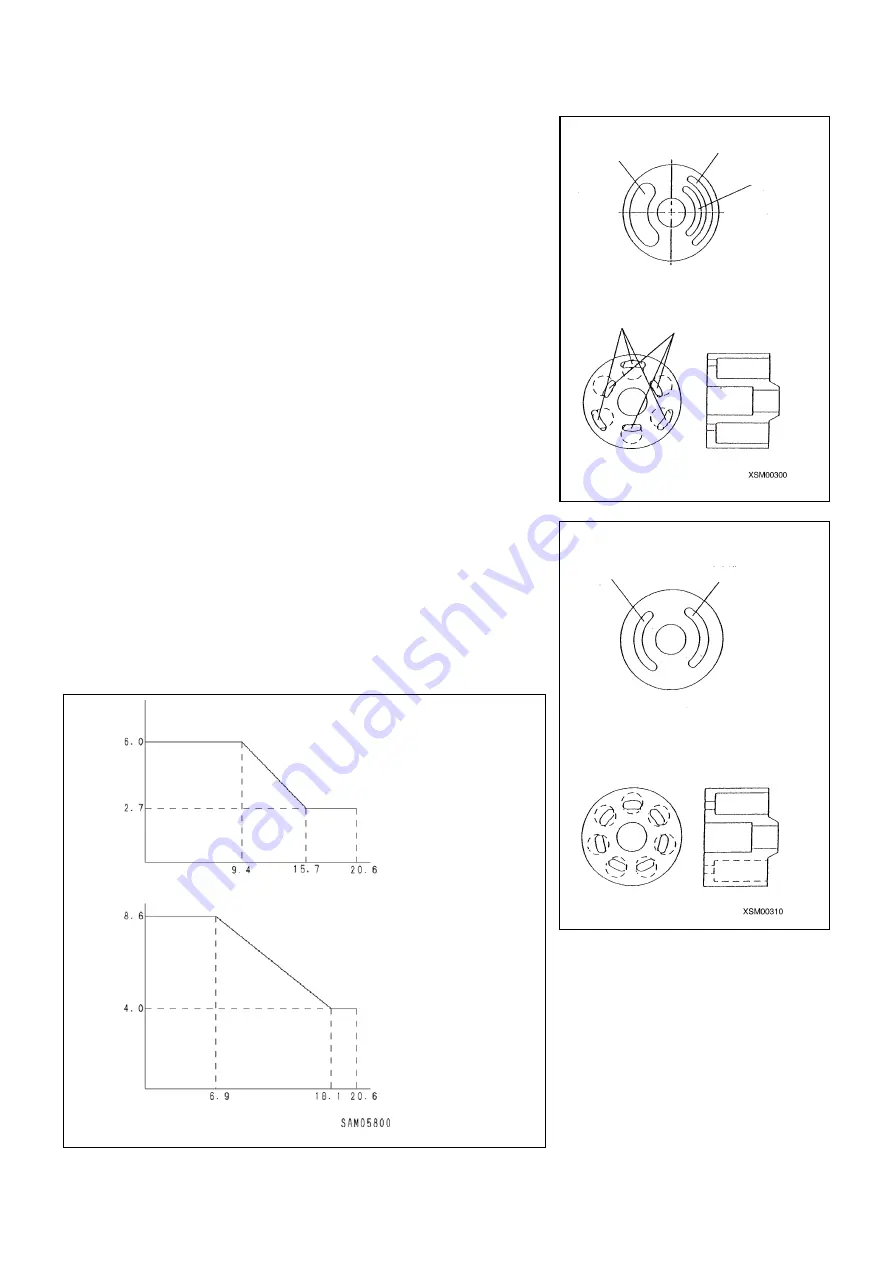
While a conventional valve plate has, as shown in the bottom right figure,
a single port each for the intake and discharge is provided, this system
comprises a pair of intake port and discharge port each on the outside
(P1) and the inside (P2).
Every other pump box in row of the cylinder barrel opens either toward the
outside (P1) or inside (P2).
While the intake occurs in similar way for both inside and outside, the
discharge of inside and outside performs different delivery actions.
Since this system has an even number of pistons, each having the same
diameter, being mounted on the common pitch circle with others, and
slides on the common swash plate, the discharge rates from outside (P1)
and inside (P2) are equal.
Further, since the sole swash plate allows the discharge rate of both P1
and P2 plates to vary equally with the variation of tilt angle of swash plate
in its variable control action, no difference in discharge rate is brought
about.
Conventional swash plate type
piston pump
Operating principle
Intake port
Discharge port P
1
Discharge port P
2
(a) Valve plate
Discharge port P
1
and opening
Discharge port P
2
and opening
Intake port
Discharge port
(a) Valve plate
(b) Cylinder barrel
Engine pump
Item number: 353S57600000
Electric pump
Item number: 329S33800001
Discharge pressure P1 = P2 (MPa)
Discharge pressure P1 = P2 (MPa)
Di
sc
harge ra
te
q1 =
q2 (
cc/
rev
)
Di
sc
harge ra
te
q1 =
q2 (
cc/
rev
)
(b) Cylinder barrel
Содержание MK0003
Страница 2: ......
Страница 8: ...0 6...
Страница 12: ...1 4 2 DIMENSIONAL DRAWING OF OUTRIGGER WIDTH...
Страница 17: ...1 9 4 WORKING RADIUS LIFTING HEIGHT...
Страница 18: ...1 10 Working range diagram Outrigger extended to maximum Main boom 1 section...
Страница 19: ...1 11 Working range diagram Outrigger extended to maximum Main boom 2 sections...
Страница 20: ...1 12 Working range diagram Outrigger extended to maximum Main boom 2 5 sections...
Страница 21: ...1 13 Working range diagram Outrigger extended to maximum Main boom 3 sections...
Страница 22: ...1 14 Working range diagram Outrigger extended to minimum Main boom 1 section...
Страница 23: ...1 15 Working range diagram Outrigger extended to minimum Main boom 2 sections...
Страница 24: ...1 16 Working range diagram Outrigger extended to minimum Main boom 2 5 sections...
Страница 25: ...1 17 Working range diagram Outrigger extended to minimum Main boom 3 sections...
Страница 26: ...1 18 5 RATED TOTAL LOAD CHART...
Страница 32: ...2 4...
Страница 33: ...2 5 1 HYDRAULIC CIRCUIT DIAGRAM 200 1176600...
Страница 34: ...2 6...
Страница 35: ...2 7 2 HYDRAULIC PIPING DIAGRAM 2 1 CRANE ROTATING PART 200 1171800...
Страница 41: ...2 13 2 2 CONTROL LINE A...
Страница 43: ...2 15 2 3CONTROL LINE B Perform spiral winding on the entire perimeter of the hose of this part...
Страница 45: ...2 17 2 4 TRAVEL LINE...
Страница 47: ...2 19 2 5 OUTRIGGER LINE...
Страница 49: ...2 21 2 6 PT LINE 102 1152000 4...
Страница 69: ...2 41...
Страница 70: ...2 42...
Страница 71: ...2 43...
Страница 76: ...2 48 4 8 ENGINE ACCESSORIES 102 1149200...
Страница 90: ...2 62 7 2 INTERNAL STRUCTURE...
Страница 120: ...2 92 Part B Writing method for wire number Two places...
Страница 123: ...2 95 Figure 1 Index point Figure 2 Connection diagram...
Страница 166: ...2 138 15 4 APPEARANCE OF OUTRIGGER ON REAR LEFT SIDE 200 2167300...
Страница 173: ...2 145 17 ELECTRIC CIRCUIT DIAGRAM 200 1176500 01...
Страница 174: ...2 146 18 ELECTRIC SYSTEM 18 1 1 WIRE HARNESS OF MACHINE BODY 1 200 1172200 1...
Страница 176: ...2 148 18 1 2 WIRE HARNESS OF MACHINE BODY 2 200 1172200 2...
Страница 179: ...2 151 19 CONTROL ASSEMBLY 19 1 CONTROLLER 1 TTC60 Pin arrangement...
Страница 180: ...2 152 TTC60 I O...
Страница 181: ...2 153 2 TTC36X Pin arrangement...
Страница 182: ...2 154 TTC36X lower part I O...
Страница 209: ...2 181 19 2 5 LIST OF CONTROLLER INPUT MONITORING...
Страница 210: ...2 182 19 2 6 LIST OF CONTROLLER ANALOG INPUT OUTPUT MONITORING...
Страница 245: ...3 9 1 2 3 ANGLE METER 360 S200M3297000...
Страница 274: ...3 38...
Страница 293: ...4 19 8 SERVICE LOCATIONS...
Страница 294: ...4 20...
Страница 296: ...5 2 1 ELECTRICAL MOTOR UNIT ASSEMBLY Unit weight 180 kg...
Страница 299: ...5 5 1 1 POWER UNIT 1 Power unit cover 2 Electric motor 3 Coupling 4 Hydraulic pump Power supply box...
Страница 323: ...5 29 3 POWER SUPPLY BOX 1 Power supply box 2 Power supply box door 3 Door handle 4 Terminal block 5 Cable inserting hole...
Страница 324: ...5 30...
Страница 325: ...5 31 4 ELECTRICAL DIAGRAM S200M3122000 01...
Страница 326: ...5 32 S200M3122000 02...
Страница 336: ...6 8 1 3 2 INTERNAL STRUCTURE OF WINCH MOTOR...
Страница 345: ...6 17 4 WORKING RADIUS LIFTING HEIGHT OF ONE FALL WINCH...
Страница 348: ......