


2-160
(2)
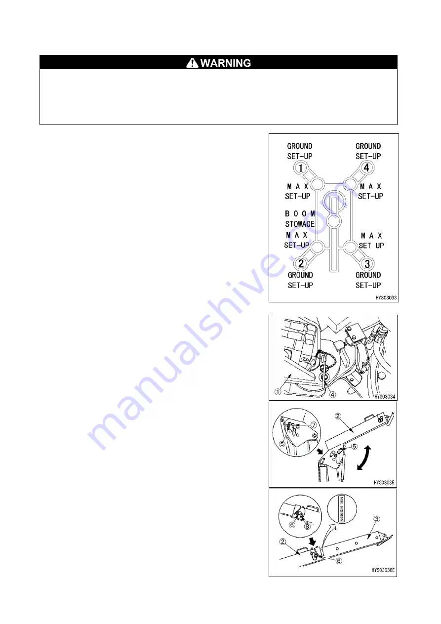
Outrigger setting/Levelling instrument display
• Do not remove, disassemble, or repair detection switches. Do not move the detection switches from the
original location to another.
• If you hit detection switches or find damage to the detection switches, be sure to check the ON/OFF
operation of the lamps on the outrigger display and operation of the crane interlock function and outrigger
interlock function.
• When setting the outriggers, check that position pins are properly inserted before use.
(2-1), (2-4), (2-9), and (2-5) outrigger setting lamps
This lamp turns on and indicates that the outriggers are set.
The lamp lights up in green when the outrigger tray sets, and blinks in
red when the tray floats (stowed).
The conditions of the outrigger trays are detected by the detection
switch at the base of the outrigger cylinder.
(2-2), (2-3), (2-8), and (2-6) outrigger extension lamps (MAX)
This lamp turns on to indicate that No. 1 outrigger rotary (1), top box
(2) and inner box (3) are at the maximum position.
The extension lamp lights up in green when the No. 1 outrigger is set
to the maximum and lights up in red when it is set to other position.
The conditions of the outrigger maximum extension are detected by
respective detection buttons.
Be sure to insert set position pins (4), (5) and (6) and use snap pins
(7) and (8) as a retainer.
Содержание MK0003
Страница 2: ......
Страница 8: ...0 6...
Страница 12: ...1 4 2 DIMENSIONAL DRAWING OF OUTRIGGER WIDTH...
Страница 17: ...1 9 4 WORKING RADIUS LIFTING HEIGHT...
Страница 18: ...1 10 Working range diagram Outrigger extended to maximum Main boom 1 section...
Страница 19: ...1 11 Working range diagram Outrigger extended to maximum Main boom 2 sections...
Страница 20: ...1 12 Working range diagram Outrigger extended to maximum Main boom 2 5 sections...
Страница 21: ...1 13 Working range diagram Outrigger extended to maximum Main boom 3 sections...
Страница 22: ...1 14 Working range diagram Outrigger extended to minimum Main boom 1 section...
Страница 23: ...1 15 Working range diagram Outrigger extended to minimum Main boom 2 sections...
Страница 24: ...1 16 Working range diagram Outrigger extended to minimum Main boom 2 5 sections...
Страница 25: ...1 17 Working range diagram Outrigger extended to minimum Main boom 3 sections...
Страница 26: ...1 18 5 RATED TOTAL LOAD CHART...
Страница 32: ...2 4...
Страница 33: ...2 5 1 HYDRAULIC CIRCUIT DIAGRAM 200 1176600...
Страница 34: ...2 6...
Страница 35: ...2 7 2 HYDRAULIC PIPING DIAGRAM 2 1 CRANE ROTATING PART 200 1171800...
Страница 41: ...2 13 2 2 CONTROL LINE A...
Страница 43: ...2 15 2 3CONTROL LINE B Perform spiral winding on the entire perimeter of the hose of this part...
Страница 45: ...2 17 2 4 TRAVEL LINE...
Страница 47: ...2 19 2 5 OUTRIGGER LINE...
Страница 49: ...2 21 2 6 PT LINE 102 1152000 4...
Страница 69: ...2 41...
Страница 70: ...2 42...
Страница 71: ...2 43...
Страница 76: ...2 48 4 8 ENGINE ACCESSORIES 102 1149200...
Страница 90: ...2 62 7 2 INTERNAL STRUCTURE...
Страница 120: ...2 92 Part B Writing method for wire number Two places...
Страница 123: ...2 95 Figure 1 Index point Figure 2 Connection diagram...
Страница 166: ...2 138 15 4 APPEARANCE OF OUTRIGGER ON REAR LEFT SIDE 200 2167300...
Страница 173: ...2 145 17 ELECTRIC CIRCUIT DIAGRAM 200 1176500 01...
Страница 174: ...2 146 18 ELECTRIC SYSTEM 18 1 1 WIRE HARNESS OF MACHINE BODY 1 200 1172200 1...
Страница 176: ...2 148 18 1 2 WIRE HARNESS OF MACHINE BODY 2 200 1172200 2...
Страница 179: ...2 151 19 CONTROL ASSEMBLY 19 1 CONTROLLER 1 TTC60 Pin arrangement...
Страница 180: ...2 152 TTC60 I O...
Страница 181: ...2 153 2 TTC36X Pin arrangement...
Страница 182: ...2 154 TTC36X lower part I O...
Страница 209: ...2 181 19 2 5 LIST OF CONTROLLER INPUT MONITORING...
Страница 210: ...2 182 19 2 6 LIST OF CONTROLLER ANALOG INPUT OUTPUT MONITORING...
Страница 245: ...3 9 1 2 3 ANGLE METER 360 S200M3297000...
Страница 274: ...3 38...
Страница 293: ...4 19 8 SERVICE LOCATIONS...
Страница 294: ...4 20...
Страница 296: ...5 2 1 ELECTRICAL MOTOR UNIT ASSEMBLY Unit weight 180 kg...
Страница 299: ...5 5 1 1 POWER UNIT 1 Power unit cover 2 Electric motor 3 Coupling 4 Hydraulic pump Power supply box...
Страница 323: ...5 29 3 POWER SUPPLY BOX 1 Power supply box 2 Power supply box door 3 Door handle 4 Terminal block 5 Cable inserting hole...
Страница 324: ...5 30...
Страница 325: ...5 31 4 ELECTRICAL DIAGRAM S200M3122000 01...
Страница 326: ...5 32 S200M3122000 02...
Страница 336: ...6 8 1 3 2 INTERNAL STRUCTURE OF WINCH MOTOR...
Страница 345: ...6 17 4 WORKING RADIUS LIFTING HEIGHT OF ONE FALL WINCH...
Страница 348: ......