


2-86
9.4 METHODS FOR OPERATION ADJUSTMENT
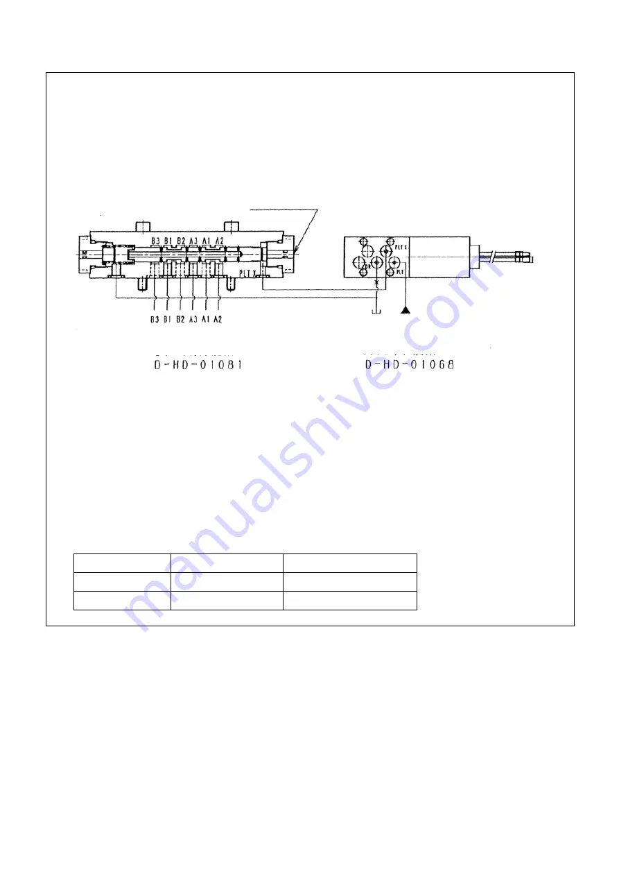
6-port directional switching valve (D-HD-01081)
1) Pilot switching valve: Energizing the solenoid of D-HD-01068 allows the PLT X port of pilot
switching valve to generate and apply pressure to the PLT X port of 6-port directional switching
valve: D-HD-01081.This pilot pressure pushes the spool of 6-port directional switching valve to
generate the flow of A1 to A3, and B1 to B3 in order to allow actuators to work. Turning off the
power supply to the solenoid causes the spring to push back the spool of 6-port switching valve
to result flows of A1 to A2 and B1 to B2.
2) When electrical checking cannot be exercised, pressing the manual operating pin of 6-port
directional switching valve enables the checking of operation.
Precautions:
1) If tightened excessively, a mounting bolt may give rise to strain in the body, resulting in
malfunctioning. Limit the tightening torque of a mounting bolt within a range of 6 to 8 N·m.
2) When tightening a mounting bolt, pay attention to prevent the O-ring from being squeezed out
and the valve from being dropped or mounted in a wrong direction.
3) This valve has been manufactured by high-precision machining. If it is clogged with a foreign
matter, even if it is a minute particle, the spool may fail to move and may no longer perform the
valve functions. To allow it to work normally, execute a sufficient flushing of piping and use a
strainer and filter with pores no larger than 100
μ
.
4) For the hydraulic oil, we recomment oils conforming to ISO VG32, ISO VG46, or an equivalent
one.
5) To maintain the specified viscosity, be cautious of oil temperature. Use hydraulic oils within the
temperature range specified below: (Recommended values)
Oil type
Oil temperature
Viscosity
ISO VG32
0 to 60°C
Approx. 15 to 340 mm
2
/s
ISO VG46
6 to 65°C
Approx. 18 to 340 mm
2
/s
Manual operation pin
6-port directional switching valve
Pilot switching valve
Содержание MK0003
Страница 2: ......
Страница 8: ...0 6...
Страница 12: ...1 4 2 DIMENSIONAL DRAWING OF OUTRIGGER WIDTH...
Страница 17: ...1 9 4 WORKING RADIUS LIFTING HEIGHT...
Страница 18: ...1 10 Working range diagram Outrigger extended to maximum Main boom 1 section...
Страница 19: ...1 11 Working range diagram Outrigger extended to maximum Main boom 2 sections...
Страница 20: ...1 12 Working range diagram Outrigger extended to maximum Main boom 2 5 sections...
Страница 21: ...1 13 Working range diagram Outrigger extended to maximum Main boom 3 sections...
Страница 22: ...1 14 Working range diagram Outrigger extended to minimum Main boom 1 section...
Страница 23: ...1 15 Working range diagram Outrigger extended to minimum Main boom 2 sections...
Страница 24: ...1 16 Working range diagram Outrigger extended to minimum Main boom 2 5 sections...
Страница 25: ...1 17 Working range diagram Outrigger extended to minimum Main boom 3 sections...
Страница 26: ...1 18 5 RATED TOTAL LOAD CHART...
Страница 32: ...2 4...
Страница 33: ...2 5 1 HYDRAULIC CIRCUIT DIAGRAM 200 1176600...
Страница 34: ...2 6...
Страница 35: ...2 7 2 HYDRAULIC PIPING DIAGRAM 2 1 CRANE ROTATING PART 200 1171800...
Страница 41: ...2 13 2 2 CONTROL LINE A...
Страница 43: ...2 15 2 3CONTROL LINE B Perform spiral winding on the entire perimeter of the hose of this part...
Страница 45: ...2 17 2 4 TRAVEL LINE...
Страница 47: ...2 19 2 5 OUTRIGGER LINE...
Страница 49: ...2 21 2 6 PT LINE 102 1152000 4...
Страница 69: ...2 41...
Страница 70: ...2 42...
Страница 71: ...2 43...
Страница 76: ...2 48 4 8 ENGINE ACCESSORIES 102 1149200...
Страница 90: ...2 62 7 2 INTERNAL STRUCTURE...
Страница 120: ...2 92 Part B Writing method for wire number Two places...
Страница 123: ...2 95 Figure 1 Index point Figure 2 Connection diagram...
Страница 166: ...2 138 15 4 APPEARANCE OF OUTRIGGER ON REAR LEFT SIDE 200 2167300...
Страница 173: ...2 145 17 ELECTRIC CIRCUIT DIAGRAM 200 1176500 01...
Страница 174: ...2 146 18 ELECTRIC SYSTEM 18 1 1 WIRE HARNESS OF MACHINE BODY 1 200 1172200 1...
Страница 176: ...2 148 18 1 2 WIRE HARNESS OF MACHINE BODY 2 200 1172200 2...
Страница 179: ...2 151 19 CONTROL ASSEMBLY 19 1 CONTROLLER 1 TTC60 Pin arrangement...
Страница 180: ...2 152 TTC60 I O...
Страница 181: ...2 153 2 TTC36X Pin arrangement...
Страница 182: ...2 154 TTC36X lower part I O...
Страница 209: ...2 181 19 2 5 LIST OF CONTROLLER INPUT MONITORING...
Страница 210: ...2 182 19 2 6 LIST OF CONTROLLER ANALOG INPUT OUTPUT MONITORING...
Страница 245: ...3 9 1 2 3 ANGLE METER 360 S200M3297000...
Страница 274: ...3 38...
Страница 293: ...4 19 8 SERVICE LOCATIONS...
Страница 294: ...4 20...
Страница 296: ...5 2 1 ELECTRICAL MOTOR UNIT ASSEMBLY Unit weight 180 kg...
Страница 299: ...5 5 1 1 POWER UNIT 1 Power unit cover 2 Electric motor 3 Coupling 4 Hydraulic pump Power supply box...
Страница 323: ...5 29 3 POWER SUPPLY BOX 1 Power supply box 2 Power supply box door 3 Door handle 4 Terminal block 5 Cable inserting hole...
Страница 324: ...5 30...
Страница 325: ...5 31 4 ELECTRICAL DIAGRAM S200M3122000 01...
Страница 326: ...5 32 S200M3122000 02...
Страница 336: ...6 8 1 3 2 INTERNAL STRUCTURE OF WINCH MOTOR...
Страница 345: ...6 17 4 WORKING RADIUS LIFTING HEIGHT OF ONE FALL WINCH...
Страница 348: ......