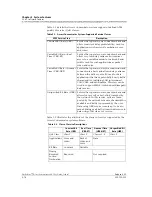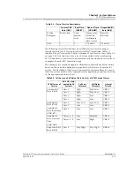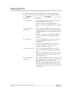
Chapter 3 System Features
AC 60 Software Features
3-30
255-700-025
PacketStar
™
Access Concentrator 60 User Guide
, Issue 1
Release 6.3.0
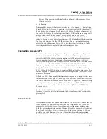
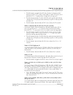
accepts the request, the specified source point(s) starts sending continuity
checks periodically to the receiving point.
A source may send continuity check cells independently of the user’s cells
sent. Source continuity check cells are sent at predefined intervals of one per
second when no user cells have been sent within one second.
If a point along the continuity check route does not receive a user cell or
continuity cell within 3.5+/- 0.5 seconds, it assumes a loss of continuity
(LOC) fault and sends AIS cells downstream. The continiuty check receiving
point declares an AIS state and sends remote defect indication (RDI) cells
upstream to the source, indicating the interruption of cell transfers in the
downstream direction. When the connection is re-established and user or
continuity check cells are received again, the affected points remove the LOC
fault condition and stop sending AIS/RDI cells.
Continuity Checks at VPC or VCC End or Connecting Points
A VPC or VCC end or connecting point (the source) sends an activation or
deactivation request to the receiving point. The receiving point responds by
either confirming or denying the request. On receiving an activation
confirmation, the source or receiving point (depending on the direction of
the action) periodically generates performance management or continuity
check cells.
Reporting
Reporting AIS and RDI: periodic notification when connection faults in the
upstream and/or downstream direction among various network elements are
affected by a defect.
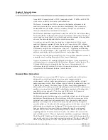
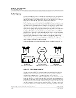
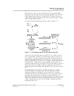
Alarm Indication Signals
A network element (NE) transmits an AIS alarm downstream when it
receives a major alarm condition such as a loss of frame. This prevents the
generation of unnecessary alarms, and maintains communications.
A VPC or VCC connecting point receives an F4/F5 AIS alarm and sends AIS
cells periodically (usually one per second) downstream, notifying all
intermediate points in the connection of a fault.
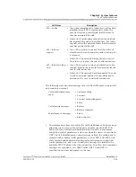
F4/F5 AIS alarms are generated when a network element receives one of the
following failure indications from the physical layer:
•
LOS (Loss of Signal) alarm
The LOS alarm indicates there are no transitions occurring in the NE
received signal. For optical interfaces, an all ones pattern results after
receiving no light pulses for a prescribed period. For electrical interfaces, a
consecutive zero pattern results after receiving no signal transitions.
You can simulate a LOS with an optical interface by turning the laser off.
•
LOF (Loss of Frame) alarm
The LOF alarm indicates the receiving equipment has lost frame
delineation.
You can stimulate a LOF alarm by injecting a frame word error by using
the Generate Frame Error dialog box.
Содержание PacketStar AC 60
Страница 38: ...Chapter 1 Getting Started 1 14 255 700 025 PacketStar Access Concentrator 60 User Guide Issue 1 Release 6 3 0 ...
Страница 128: ...Chapter 3 System Features 3 80 255 700 025 PacketStar Access Concentrator 60 User Guide Issue 1 Release 6 3 0 ...
Страница 404: ......
Страница 406: ......
Страница 408: ......
Страница 409: ......

