TS, TR, TX engines workshop manual
39
7. On TX engines:
Clean and dry the cylinder head clearance shims, the cylinder
barrel and crankcase mating surfaces.
Place the shims, dry, onto the bottom of the cylinder barrel.
8. Turn the crankshaft crankpin to TDC.
9. To protect the crankshaft journal from possible damage, fit
a suitable tube over each connecting rod bolt and secure it
with a hand tight nut.
10. On TS/TR engines:
Ensure the deeper cylinder barrel fins will be facing towards
the manifold side and 'CAMSHAFT SIDE' on the piston crown
will face towards the camshaft.
10a. On TX engines:
Ensure the connecting rod identification marks will face
towards the camshaft.
11. Lower the cylinder and piston assembly into position.
12. Push down on the top of the piston as the crankcase is
rotated until the crankshaft crankpin is at BDC.
13. Remove the protective tubes.
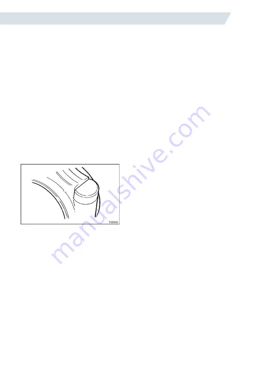
14. Ensure the connecting rod cap bolt head is correctly located
against the shoulder on the connecting rod as shown
below.
15. Fit the big end bearing cap ensuring the identification
numbers are on the same side and identical.
T SERIES ENGINES WORKSHOP MANUAL
42
5.To protect the crankshaft journal from possible
damage, fit a suitable tube over each connecting
rod bolt and secure it with a hand tight nut.
6.Rotate the crankcase until the same piston is at
TDC.
7.Mark the cylinder for position and number.
8.Remove the tube securing the barrel.
9.Lift off the barrel, piston and connecting rod as a
complete assembly.
10.Remove the tubes from the big end.
11.Replace the big end bearing cap.
12.Remove the piston from the cylinder barrel.
13.Thoroughly clean the cylinder barrel and check
for scoring and wear.
Cylinder Barrel Replacement
1.Fit the piston to the connecting rod.
On TS/TR engines ensure the wording 'CAMSHAFT
SIDE' on the piston crown is the same side as
the identification marks on the connecting rod big
end.
2.Insert the gudgeon pin and two circlips; ensure
the circlips are correctly located in the grooves.
3.Fit the piston rings in the order as shown in
'Figure 2.40.1'
4.Ensure the piston ring gaps are staggered
and fit the piston into the cylinder barrel while
compressing the rings.
5.If necessary, fit new big end bearing shells
ensuring they are correctly located in both the
connecting rod and cap.
6.On TS/TR engines:
Coat the bottom jointing face surface of the cylinder
barrel with Hylomar PL32M.
Fit a new joint and coat it with Hylomar PL32M.
7.On TX engines:
Clean and dry the cylinder head clearance shims,
the cylinder barrel and crankcase mating
surfaces.
Place the shims, dry, onto the bottom of the cylinder
barrel.
8.Turn the crankshaft crankpin to TDC.
9.To protect the crankshaft journal from possible
damage, fit a suitable tube over each connecting
rod bolt and secure it with a hand tight nut.
10.On TS/TR engines:
Ensure the deeper cylinder barrel fins will be facing
towards the manifold side and 'CAMSHAFT
SIDE' on the piston crown will face towards the
camshaft.
10a.On TX engines:
Ensure the connecting rod identification marks will
face towards the camshaft.
11.Lower the cylinder and piston assembly into
position.
12.Push down on the top of the piston as the
crankcase is rotated until the crankshaft
crankpin is at BDC.
13.Remove the protective tubes.
14.Ensure the connecting rod cap bolt head is
correctly located against the shoulder on the
connecting rod as shown below.
15.Fit the big end bearing cap ensuring the
identification numbers are on the same side and
identical.
Figure 2.39.1 Bearing Cap Bolt Head Location
16.Replace the connecting rod nuts and torque
them to 43.5Nm (32.0lbf ft).
It is recommended that connecting rod bolts and
nuts are replaced at every major overhaul.
2.40 THE PISTON AND
CONNECTING ROD
The piston is manufactured from low expansion
alloy and has a machined recessed combustion
chamber in the crown. All pistons are fitted with
three cast iron rings except certain TS builds which
have five rings.
The gudgeon pin is retained by two circlips and
runs in a bush in the small end of the connecting
rod.
The forged steel connecting rod is connected to
the crankpin by a conventional big end bearing, the
cap being held in position by two bolts and nuts.
The two halves of the big end bearing are steel
backed copper lead and are precision finished and
should not be scraped or touched up in any way.
The gudgeon pin is a clearance fit in the small end
bush.
The Piston Rings
Firing Ring
A barrel lapped chrome ring is situated at the top
of the piston and is tapered on the sides to prevent
sticking in the groove.
Figure 2.39.1 Bearing Cap Bolt Head Location
16.Replace the connecting rod nuts and torque them to 43.5Nm
(32.0lbf ft).
It is recommended that connecting rod bolts and nuts are
replaced at every major overhaul.
2.40 The Piston and Connecting Rod
The piston is manufactured from low expansion alloy and has
a machined recessed combustion chamber in the crown. All
pistons are fitted with three cast iron rings except certain TS
builds which have five rings.
The gudgeon pin is retained by two circlips and runs in a bush
in the small end of the connecting rod.
The forged steel connecting rod is connected to the crankpin by
a conventional big end bearing, the cap being held in position
by two bolts and nuts. The two halves of the big end bearing
are steel backed copper lead and are precision finished and
should not be scraped or touched up in any way.
The gudgeon pin is a clearance fit in the small end bush.
The Piston Rings
Firing Ring
A barrel lapped chrome ring is situated at the top of the piston
and is tapered on the sides to prevent sticking in the groove.
Compression Ring
Two compression rings are fitted to the five ring piston and one
on the three ring piston. They have a tapered face in contact
with the barrel, one surface on each is marked 'TOP' and the
rings must be fitted the correct way up with 'TOP' towards the
piston crown.
Oil Control Ring
One conformable type, with a spring expander, is fitted above
the gudgeon pin and a slotted scraper ring is fitted below the
gudgeon pin on five ring pistons. On a three ring piston only
one ring is fitted above the gudgeon pin.
Removing a Piston
1. Remove the cylinder barrel together with the piston.
2. Withdraw the piston from the barrel.
3. Release the circlip from one end of the gudgeon pin.
4. Push out the gudgeon pin.
If the pin is tight, place the piston in hot water until it can be
removed; it may be necessary to protect the hands.
5. Using a suitable piston ring expander remove the piston rings.
Inspection and Servicing
a. Clean the piston, removing all traces of carbon from the
crown, ring grooves and oil holes.
b. Check all the piston rings in the cylinder barrel for the correct
gap clearance.
c. Clean the connecting rod and examine for bending and
twisting.
d. Examine the small end bush for wear.
e. If the big end has been dismantled because of metal failure
the oil passages in the crankshaft must also be examined for
obstruction and fragments of metal.
Refitting a Piston
1. Fit the piston to the connecting rod.
On TS/TR engines ensure the wording 'CAMSHAFT SIDE' on
the piston crown is the same side as the identification marks
on the connecting rod big end.
2. Insert the gudgeon pin and replace the circlips.
3. Using a suitable piston ring expander replace the piston rings
in the order as shown below.
Содержание TS/TR1
Страница 1: ...P027 08270 edition 8 April 2021 TS TR TX Engines Workshop Manual T SERIES ...
Страница 80: ...TS TR TX engines workshop manual 80 T SERIES ENGINES WORKSHOP MANUAL 90 ct ical Wiring i g ...
Страница 81: ...TS TR TX engines workshop manual 81 T SERIES ENGINES WORKSHOP MANUAL 91 Elect i al Wiring Diagram ...
Страница 82: ...TS TR TX engines workshop manual 82 T SERIES ENGINES WORKSHOP MANUAL 92 ctr ca Wi ing Diagrams ...
Страница 83: ...TS TR TX engines workshop manual 83 T SERIES ENGINES WORKSHOP MANUAL 93 Electrical Wiring iagram ...
Страница 84: ...TS TR TX engines workshop manual 84 T SERIES ENGINES WORKSHOP MANUAL 94 ect ica Wiring Diagrams ...
Страница 85: ...TS TR TX engines workshop manual 85 T SERIES ENGINES WORKSHOP MANUAL 95 ...
Страница 99: ...TS TR TX engines workshop manual 99 ...


