


24
MUL
TI V Hydro Kit Medium T
emperature (K2) Installation Manual
Due to our policy of continuous product innovation, some specifications may change without notification.
©LG Electronics U.S.A., Inc., Englewood Cliffs, NJ. All rights reserved. “LG Life’s Good” is a registered trademark of LG Corp.
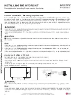
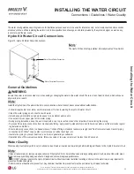
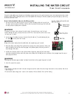
Figure 4: Foundation Requirements and Anchoring.
3
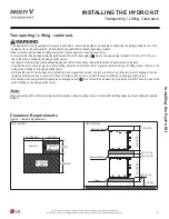
Anchoring the Hydro Kit Unit
The figure below shows the proper location and mounting of the anchor bolts for the Hydro Kit.
• Securely fasten the Hydro Kit to the supporting base.
• If not otherwise directed by the structural engineer or local codes, Use 7/16 inch or 1/2 inch diameter J-bolts. Use a hexagon nut with a
spring washer.
• Include enough space for refrigerant piping and electrical wiring when installing through the bottom of the unit.
•
$OZD\VLQVWDOOSHUPRXQWLQJLQVWUXFWLRQDQGGHWDLOVSURYLGHGE\WKHGHVLJQRUVWUXFWXUDOH\GUR.LWZLOOIDOOFDXVLQJSURGXFWGDPDJH
•
$OOUHIHUHQFHGPDWHULDOVDUHWREHILHOGVXSSOLHG,PDJHVDUHQRWWRVFDOHDUHIRUUHIHUHQFHRQO\DQGDUHQRWLQWHQGHGWREHXVHGIRUGHVLJQ
SXUSRVHV
$OZD\VLQVWDOOSHUPRXQWLQJLQVWUXFWLRQDQGGHWDLOVSURYLGHGE\WKHGHVLJQRUVWUXFWXUDOH\GUR.LWZLOOIDOOFDXVLQJSK\VLFDOLQMXU\RUGHDWK
INSTALLING THE HYDRO KIT
Foundation and Mounting Requirements, Anchoring
•
(QVXUHWKDWWKHIORRUFKRVHQORFDWLRQKDVHQRXJKVWUHQJWKWRVXSSRUWWKHZHLJ\GUR.LW,ILWGRHVQRWKDYHVXIILFLHQWVWUHQJWKWKH
+\GUR.LWZLOOIDOODQGFDXVHGDPDJHWRWKHXQLW
•
(QVXUHWKDWWKHIORRUFKRVHQORFDWLRQKDVHQRXJKVSDFHIRUSLSHVDQGZLULQJWKHFRQGHQVDWHGUDLQFRQQHFWLRQDQGWKHIORRUGUDLQ,P
SURSHULQVWDOODWLRQFDQUHVXOWLQXQLWPDOIXQFWLRQ
•
(Q\GUR.LWLVILUPO\DWWDFKHGWRWKHIRXQGDWLRQ$Q\GHILFLHQF\LQLQVWDOODWLRQZLOOFDXVHXQLWWRIDOOUHVXOWLQJLQGDPDJHWRWKHXQLW
General Foundation / Mounting Requirements
Securely attach the Hydro Kit to a concrete pad, base rails, H-beam, mounting platform anchored to the building structure, or other accept-
able support structure designed by a structural engineer. Refer to dimensional drawing in this manual, and follow the applicable local codes
for clearance, mounting, anchor, and vibration attenuation requirements. Noise and vibration could transfer to the floor or walls, so install
rubber anti-vibration isolation pads between the mounting feet and the base chosen by the acoustics engineer. The base pad must be more
than 8 inches (200 mm). Secure the feet to the base using washers and nuts.
•
(QVXUHWKDWWKHIORRUFKRVHQORFDWLRQKDVHQRXJKVWUHQJWKWRVXSSRUWWKHZHLJ\GUR.LW,ILWGRHVQRWKDYHVXIILFLHQWVWUHQJWKWKH
+\GUR.LWZLOOIDOODQGFDXVHSK\VLFDOLQMXU\RUGHDWK
•
(Q\GUR.LWLVILUPO\DWWDFKHGWRWKHIRXQGDWLRQ$Q\GHILFLHQF\LQLQVWDOODWLRQZLOOFDXVHXQLWWRIDOOUHVXOWLQJLQSK\VLFDOLQMXU\RU
GHDWK
CAUTION
$YRLGSODFLQJWKHXQLWLQDORZO\LQJDUHDZKHUHZDWHUZLOODFFXPXODWHDQGIUHH]HRQVLGHZDONVRUGULYHZD\V:DWHUFRXOGIUHH]HFDXVLQJDQ
XQVDIHFRQGLWLRQ


