58
MUL
TI V Hydro Kit Medium T
emperature (K2) Installation Manual
Due to our policy of continuous product innovation, some specifications may change without notification.
©LG Electronics U.S.A., Inc., Englewood Cliffs, NJ. All rights reserved. “LG Life’s Good” is a registered trademark of LG Corp.
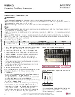
Connecting the Independent Power Module
(Included with the Hydro Kit; Model No. PRIPO)
The Independent Power Module is supplied with the Hydro Kit and is a required accessory. The Independent Power Module is used as
backup power to close the EEV in case of power failure during an outdoor unit oil return or defrost cycle. The Independent Power Module
protects from a plate heat exchanger burst. If a power outage occurs during normal operation, a plate heat exchanger burst could happen
during oil-return and defrost cycle in cooling mode.
• Incorrect wiring will lead to fire, electric shock, bodily injury and / or death.
•
7KH+\GUR.LWDQGWKH,QGHSHQGHQW3RZHU0RGXOHPXVWEHLQVWDOOHGLQDQLQWHULRUVSDFH([SRVXUHWRZHDWKHUZLOOGDPDJHWKHZLULQJDQG
will lead to fire, electric shock, bodily injury and / or death.
• Incorrect wiring will lead to independent power module malfunction or damage.
•
,IWKH,QGHSHQGHQW3RZHU0RGXOHLVQRWLQVWDOOHGLWZLOOFDXVHVHULRXVGDPD\GUR.LWKHDWH[FKDQJHUZKHQHOHFWULFLW\FXWRIIGXU
-
ing product operation.
•
7KH+\GUR.LWDQGWKH,QGHSHQGHQW3RZHU0RGXOHPXVWEHLQVWDOOHGLQDQLQWHULRUVSDFH([SRVXUHWRZHDWKHUZLOOGDPDJHWKHZLULQJDQG
will lead to product malfunction.
•
0DLQWDLQWZHQW\PLQXWHVRIFRQWLQXRXVSRZHUWRWKHSRZHUPRGXOHNLWWRHQVXUHWKDWWKH((9LVIXOO\FKDUJHGDQGFDQFORVHSURSHUO\
Refer to the Independent Power Module Installation Manual for more detailed information.
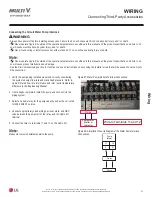
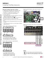
1. Turn power off at the circuit breaker.
2. Open the Hydro Kit front panel / control box cover.
3. Assemble the cover of the Independent Power Module. Secure
the Independent Power Module to the outside of the Hydro Kit
control panel with bolts.
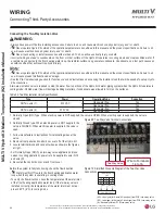
4. Route the Independent Power Module wiring through an opening
in the bottom of the Hydro Kit.
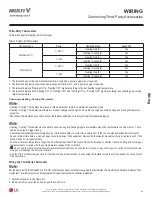
5. Disconnect the EEV cable harness plug from the socket labeled
CN-EEV on the Hydro Kit.
6. Connect the Independent Power Module wire harness No. 1
labeled CN-EEV/LOAD to the Hydro Kit EEV valve.
7. Connect the Independent Power Module dual plug wiring harness
No. 2 labeled CN-EEV/MAIN) to the Hydro Kit’s PCB terminals
labeled CN-EEV and CN-WRITE.
8. Replace the Hydro Kit control box cover and front panel.
Figure 50: Power Module Wiring Termination Detail (Terminal Loca-
tion May Vary).
Figure 49: Routing Power
Module Wiring.
Figure 48: Securing Power Module to
the Hydro Kit.
To Hydro Kit EEV
EEV
CN_EEV/MAIN
CN_EEV/LOAD
Harness 1
CN-EEV
CN-WRITE
Harness 2
WIRING
Connecting Included Hydro Kit Accessories
Wiring Pre-Check
• Verify power wiring and communications cables are all properly
terminated.
• Test the line voltage wiring insulation. Conduct a Mega-ohm test
UHDFKLQJDYDOXHRI0ȍRUKLJKHU7HVWWKHLQVXODWLRQUHVLVWDQFH
between the Hydro Kit power wiring terminal block and ground us-
ing a DC mega-ohm tester (DC 500V).


