64
MUL
TI V Hydro Kit Medium T
emperature (K2) Installation Manual
Due to our policy of continuous product innovation, some specifications may change without notification.
©LG Electronics U.S.A., Inc., Englewood Cliffs, NJ. All rights reserved. “LG Life’s Good” is a registered trademark of LG Corp.
WIRING
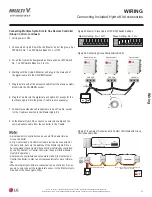
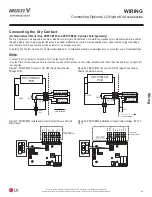
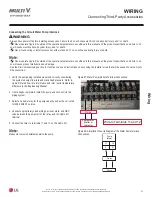
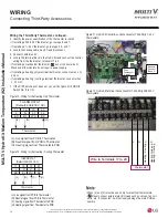
Installation Option No. 2
X: Relay (A point of contact with a fixed DC 0.5 ~ 1 mA)
SW: Distant ON / OFF Switch
Control Cable (Hydro Kit to Relay Circuit)
• Use a field-supplied communications cable that is maximum 32.8
feet (10 m) (see local, state, and federal requirements for AWG
size).
Hydro Kit
Supplied
X
1.64 feet (0.5 m)
Max. 32.8 feet
(10 m)
X
Relay Circuit
Relay
Power
Supply
SW
PCB
Field Installation
CN_EXT
CN_EXT
Hydro Kit PCB
Adapter Cable
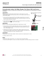
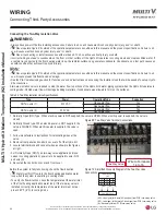
Connecting the External Controller
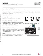
1. Verify that the power to the Hydro Kit is OFF.
2. Remove the front panel and control box cover to the Hydro Kit.
3. Locate CN_EXT on the main PCB of the Hydro Kit.
4. Route the external controller cable through the bottom of the
control panel, and insert its plug into CN_EXT
5. Re-install the Hydro Kit control box cover and front panel.
6. Connect the cable to the external controller.
7. System needs to be set to recognize that an external control-
ler is installed. Enter installer setting mode on the Hydro Kit
controller, and set the function code.
Figure 62: X: Relay.
See the Pre-Commissioning section for function codes and instructions
on accessing Installer mode that will be needed to set up other Hydro Kit
accessories.
Figure 63: Connecting the External Controller.
Connecting an External Controller
Use the CN_EXT connection if the application requires automatic operation control depending on an external input signal (ON / OFF) with
preset mode. Connect the external controller cable to CN_EXT, and set its function on the Hydro Kit controller (included with the Hydro Kit)
through the Installer Setting Mode.
Choose from set values 0 ~ 3 (CN_EXT port setting).
• 0: Not Used (Default)
• 1: Simple Operation
• 2: Simple Dry Contact Operation
• 3: Single Emergency Stop
See the Pre-Commissioning section for detailed information.
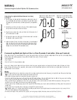
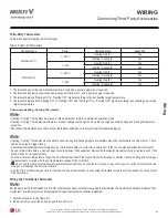
Installation Option No. 1
SW: Single Pole Switch
• Select a component with contacts for extremely low amperage.
• DC 5 V ~ 12 V is used at the contact point.
• Switch load is approximately 0.5 ~ 1 mA.
• Use a field-supplied communications cable that is maximum 32.8 feet (10 m) (see
local, state, and federal requirements for AWG size).
Hydro Kit
PCB
Supplied Field
Installation
SW
1.64 feet
(0.5 m)
Max. 32.8 feet (10 m)
CN_EXT
Figure 61: SW: Single Pole Switch.
Connecting Optional LG Hydro Kit Accessories

