


37
Installing the W
ater Circuit
Due to our policy of continuous product innovation, some specifications may change without notification.
©LG Electronics U.S.A., Inc., Englewood Cliffs, NJ. All rights reserved. “LG Life’s Good” is a registered trademark of LG Corp.
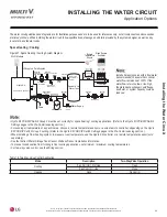
INSTALLING THE WATER CIRCUIT
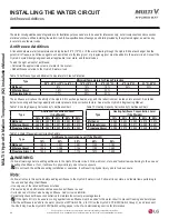
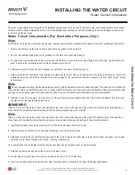
Water Circuit Components
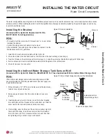
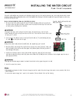
Installing the Strainer
(Included with the Hydro Kit; Replacement Part No.
MJC57132402; For All Applications)
• Thoroughly flush the water circuit (if present and / or in use) before
installing the strainer.
• Continue flushing period until water circuit is clean.
• After installation, periodically check and clean the strainer. See the
Maintenance section for guidelines.
1. Install the 50 mesh strainer provided with the Hydro Kit.
2. Check the strainer direction and install on the inlet side of the heat exchanger (see image).
3. Treat the threads on the water pipe with joint compound, or wrap the water pipe threads thoroughly with Teflon tape.
4. Service access port must be installed downward within 45 degrees of the vertical plane.
5. Check for leaks on the connection.
Figure 18: Strainer Installation.
Water In
Strainer
Side
Front
45°
Flow
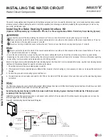
Installing the Indirect Water Storage Tank Sensor Well
(Included with the Hydro Kit; Model No. MEG61846102; For Those Applications With An Indirect Water Storage Tank)
Figure 19: Indirect Water Storage Tank Sensor Well Installation.
If the indirect water storage tank includes an existing sensor well that
can accommodate the LG factory-provided sensor (see next page), use
it and skip this procedure.
1. Drill and thread a 1/2
"
FPT hole in the tank wall at the tank manu-
facturer’s recommended location.
2. Remove cap and sensor from the well and place in a secure
location.
3. If welding the sensor well to the tank, insert it into the threaded
hole and rotate until the threads on the neck bottom out. Weld the
sensor well to the tank and pressure test as necessary.
4. If not welding, wrap the threads of the sensor well about eight (8)
times with Teflon tape. Insert the sensor well into the threaded
hole in the tank wall. Turn clockwise until secure, and then final-
ize tightening using a socket or open-end wrench.
PT 1/2 Inch
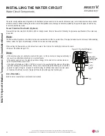
Sensor
Holder Cap
Inside Indirect Hot
Water Storage Tank
Water Tank Outer Wall
Water Tank
Temperature
Sensor Bulb
Sensor
Well
Water
Pipe
Install
PT 1/2
Inch Bolt
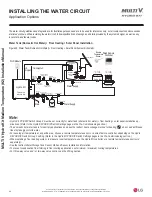
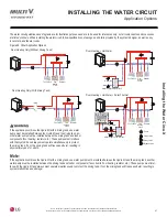
The water circuit guidelines and diagrams are for illustrative purposes and are to be used for references only; not all components and accessories
DUHOLVWHGRUVKRZQ:KHQLQVWDOOLQJWKHZDWHUFLUFXLWIROORZVSHFL¿FDWLRQVGUDZLQJVDQGGHWDLOVSURYLGHGE\WKHV\VWHPGHVLJQHUDVZHOODVDQ\
local, state, and federal codes.