


43
Installing the W
ater Circuit
Due to our policy of continuous product innovation, some specifications may change without notification.
©LG Electronics U.S.A., Inc., Englewood Cliffs, NJ. All rights reserved. “LG Life’s Good” is a registered trademark of LG Corp.
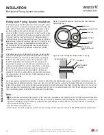
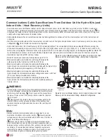
The water circuit guidelines and diagrams are for illustrative purposes and are to be used for references only; not all components and accessories
DUHOLVWHGRUVKRZQ:KHQLQVWDOOLQJWKHZDWHUFLUFXLWIROORZVSHFL¿FDWLRQVGUDZLQJVDQGGHWDLOVSURYLGHGE\WKHV\VWHPGHVLJQHUDVZHOODVDQ\
local, state, and federal codes.
INSTALLING THE WATER CIRCUIT
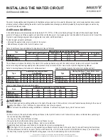
Application Options
Application Options
Water Tank (Domestic Hot Water) + Floor Heating (Factory Default Setting)
Mode
Description
Three-Way Valve Operation
Two-Way Valve Operation
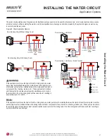
Cooling
Fan Coil Unit - Not Use
Floor Heating
Open
Fan Coil Unit - Use
Floor Heating
Close
Heating
Priority - Water Tank (Domestic Hot Water)
Water Tank (Domestic Hot Water)
No Control
Priority - Floor Heating
Floor Heating
No Control
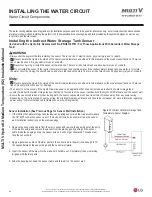
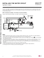
Drain
Water Supply
&RROLQJĺ&ORVH
Wired Remote
Controller
Wi-Fi Module
Water Supply
Field Supplied
LG
Supplied
Remote
Temperature
6HQVRU
)ORZ6\GUR.LW
Hydro Kit
Balancing
Valve with
Flow Meter
Automatic Air
Separator
3UHVVXUH
Relief Valve
Service Port
'UDLQ9DOYH
3UHVVXUH
Meter Check
Valve
Shut-Off
Valve
Shut-Off
Valve
Shut-Off
Valve
Shut-Off
Valve
Floor Heating
Fan Coil Unit
Water Tank
Temperature
6HQVRU
'RPHVWLF
Hot
Water
Tank
Strainer
Water Pump
Magnetic Dirt
Separator
Service Port
'UDLQ9DOYH
([SDQVLRQ7DQN
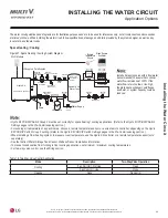
Figure 25: Water Tank (Domestic Hot Water) + Floor Heating System Schematic.
• Verify that Hydro Kit PCB DIP Switch Group 2 is set correctly for water tank (domestic hot water) + floor heating installation applications
(this application is the factory default setting). (Refer to the Hydro Kit DIP Switch Settings pages in the Pre-Commissioning section.)
• The domestic hot water tank is for hot water applications and uses the indirect heat exchange method for heating;
do not add anti-
freeze like ethylene glycol to its water.
• For sensing air temperature at a specific area, choose a remote temperature sensor or a wired remote controller, depending on the Hydro
Kit PCB DIP Switch Group 3 setting. (Refer to the Hydro Kit PCB DIP Switch Settings pages in the Pre-Commissioning section.)
• When installing a floor heating system, to measure room temperature, use the Hydro Kit controller or a remote temperature sensor (sold
separately).
• See the Indirect Water Storage Tank Sensor Well and Sensor Installation information. To prevent condensation from forming in floor cooling
applications, set minimum / maximum cooling temperatures.
• For three-way valve and / or two-way valve control, see the Wiring section.
Table 17: Three-Way Valve and Two-Way Valve Control Application.
• When selecting a water tank,
ALWAYS use an INDIRECT tank
where the Hydro Kit water circuit
is isolated from the domestic
water system. Failure to follow
instructions will result in product
malfunction.
• The heating operation mode of
the water tank (domestic hot
water) is not a mode selection
using the remote controller. The
heating operation mode switches
the three-way valve operation to
the water tank operation based
on the water tank temperature.
• It is impossible to operate water
tank (domestic hot water) during
cooling mode.