


68
MUL
TI V Hydro Kit Medium T
emperature (K2) Installation Manual
Due to our policy of continuous product innovation, some specifications may change without notification.
©LG Electronics U.S.A., Inc., Englewood Cliffs, NJ. All rights reserved. “LG Life’s Good” is a registered trademark of LG Corp.
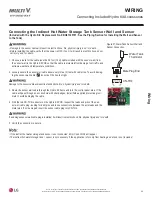
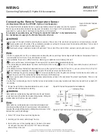
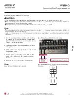
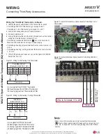
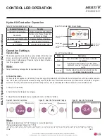
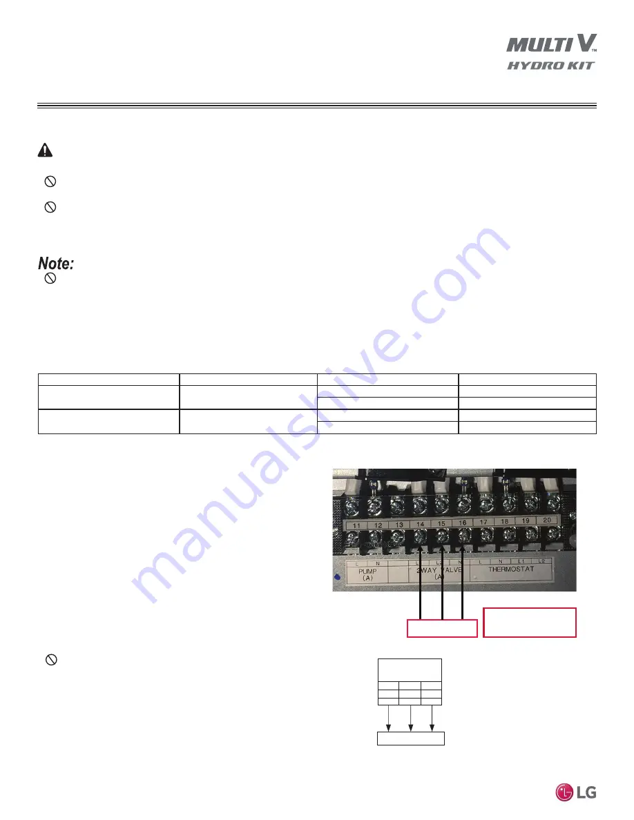
(NO): Live signal (for Normally Open type) from PCB to two-way valve.
(NC): Live signal (for Normalyl Closed type) from PCB to two-way valve.
(N): Neutral signal from PCB to two-way valve.
Two-Way Valve
(NO)
(NC)
(N)
Two-Way Valve
(A)
14
L1
BR
15
L2
WH
16
N
BL
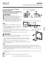
Connecting the Two-Way Isolation Valve
WARNING
• Always have power off before installing accessories. Failure to do so will cause electric shock, physical injury, and / or death.
•
Never operate Hydro Kit outside of the operational parameters as outlined in this manual and the product specifications. Failure to do
so will cause electric shock, physical injury, and / or death.
•
Never touch wiring or install accessories with wet hands. To do so will cause bodily injury or death.
• Incorrect wiring can lead to condensate on the floor or other surfaces if the Hydro Kit operates in cooling mode and creates chilled water. If
a radiator is connected to the floor heating water loop, the radiator surface can generate condensate. Condensate on a foot path causes an
unsafe condition that will result in physical injury.
•
Never operate Hydro Kit outside of the operational parameters as outlined in this manual and the product specifications. Failure to do
so will cause product malfunction and damage.
• See the Pre-Commissioning section for function codes and instructions on accessing the Installer mode that will be needed to set up Hydro
Kit accessories.
A two-way isolation valve is required to stop the water flow to portions of the Hydro Kit’s water piping system when the Hydro Kit operates in
cooling mode. Chilled water flow will damage building materials, if condensate was allowed to form on the surfaces.
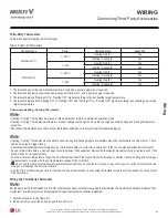
Type
Power
Operating Mode
Supported
NO Two-wire (1)
230 V AC
Close water flow
Yes
Open water flow
Yes
NC Two-wire (2)
230 V AC
Close water flow
Yes
Open water flow
Yes
1. Normally Open (NO) Type. When electric power is NOT supplied, the valve is OPEN. When electric power is supplied, the valve is
closed.
2. Normally Closed type. When electric power is NOT supplied, the
valve is CLOSED. When electric power is supplied, the valve is
open.
Table 24:
7ZR:D\,VRODWLRQ9DOYH6SHFL¿FDWLRQV
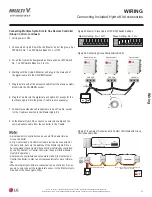
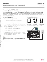
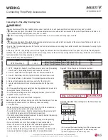
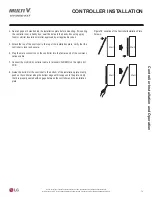
1. Follow manufacturer’s instructions for terminating wires at the
valve.
2. Remove front panel and control box cover off of the Hydro Kit.
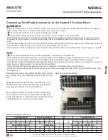
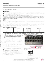
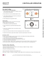
3. Locate terminal block and connect wires as shown in the figures
at right.
• For Normally Open (NO) Type two-way valve applications (close
valves in cooling operation), power is to be supplied to wire (NO)
and wire (N).
4. Re-install the control box cover and front cover.
Figure 69: Two-Way Valve Terminal Connections.
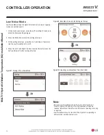
Wire to Terminals
14 to 16
Two-Way Valve
Figure 70:
6LPSOL¿HG&ORVH8S'LDJUDPRIWKH7ZR:D\9DOYH
Connections.
Before the system is fully functioning, check the flow direction.
•
Water must NOT flow into the floor heating application water
loop when the system is operating in cooling mode.
• To verify the flow direction, check the temperature at the water inlet
of the floor heating application water loop. If the two-way valve is
installed correctly, the temperature at the water inlet must not ap-
proach 42°F (6°C) in cooling mode.
WIRING
Connecting Third-Party Accessories


