


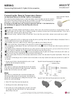

55
W
iring
Due to our policy of continuous product innovation, some specifications may change without notification.
©LG Electronics U.S.A., Inc., Englewood Cliffs, NJ. All rights reserved. “LG Life’s Good” is a registered trademark of LG Corp.
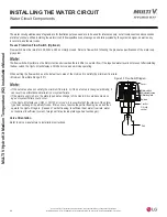
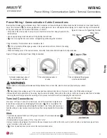
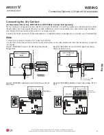
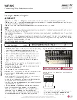
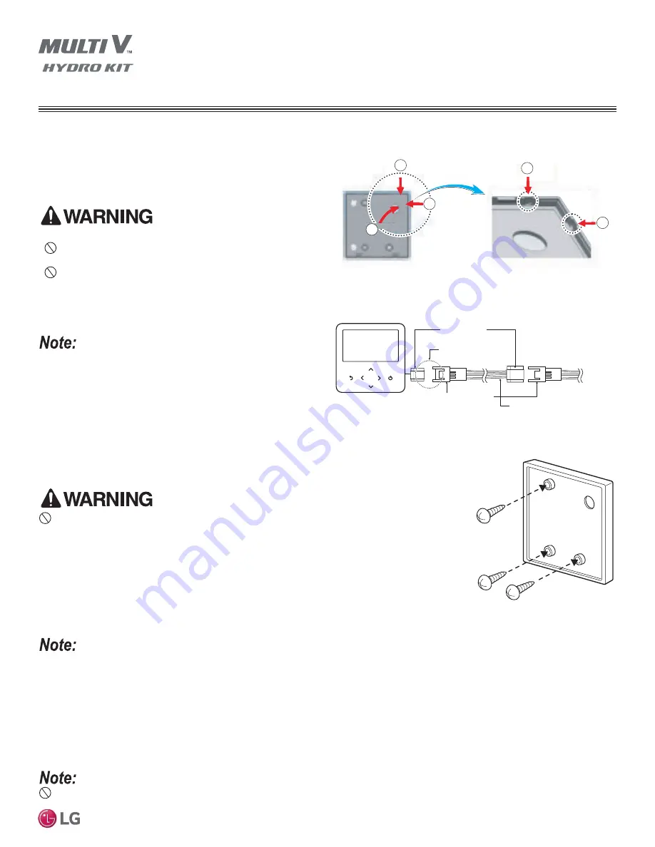
1. If not already done so, separate the Hydro Kit controller from its installation plate.
• To separate, insert a small screwdriver into one of the two holes at the bottom of the installation
plate. Gently turn clockwise.
• Repeat for the remaining hole, and then gently pull on the bottom of the controller body.
'RQRWGDPDJHWKHFRQWUROOHUFRPSRQHQWVZKHQVHSDUDWLQJ7KHUHLVULVNRI¿UHHOHFWULFVKRFNDQG
physical injury or death if the electrical components are damaged.
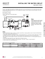
2. Determine how the factory-provided Hydro Kit communications cable (female socket) will be
routed to the controller. Choose either through the back, using the top groove, or using right
groove.
• If using the top or right groove, use needle nose pliers to carefully break off the tab.
• If using the back, route the communications cable through the handy box or wall, and through the
large hole in the installation plate.
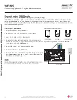
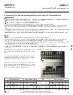
Connecting the Hydro Kit Wired
Remote Controller
(Included with the Hydro Kit; Part No. AKB74855309; See
the Installation Section for Placement Information; See the
Controller Section for Operation Information)
• Always have power off before installing the controller.
•
Never operate Hydro Kit outside of the operational parameters
as outlined in this manual and the product specifications.
•
Never touch wiring or install accessories with wet hands.
• When drilling holes for the communication cable and the screws, take
care not to damage wiring that is routed through the wall. There is risk
RI¿UHHOHFWULFVKRFNH[SORVLRQDQGSK\VLFDOLQMXU\RUGHDWK
• See the Installation section for guidelines on where to place the
controller.
• The controller is designed to be surface mounted. Recessing the
controller will damage the temperature sensor, and cause it to
misread the zone temperature.
Figure 40: Routing the Communications Cable.
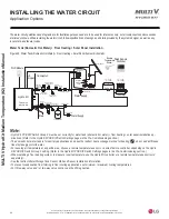
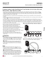
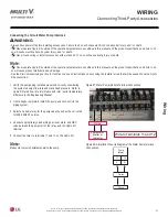
Figure 41: Hydro Kit Controller Communications Cable Termination
Detail.
2
2
1
3
3
Cable Grooves
1. Back
2. Top
3. Right
Optional LG Extension Cable
(Sold Separately)
Male Plug
Check if Connector
is Correctly Installed.
Female Plug
Hydro Kit
OK
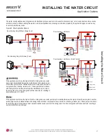
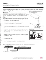
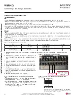
Figure 42: Location of the Controller
Installation Plate Screws.
• Use the LG-provided communications cable and the LG Hydro Kit Controller (controller and cable included with the Hydro Kit).
•
,IWKHGLVWDQFHEHWZHHQWKHFRQWUROOH\GUR.LWLVPRUHWKDQIHHWPXVHDQ/*&DEOH([WHQVLRQ.LWVROGVHSDUDWHO\
•
7KHPD[LPXPOHQJWKRIWKHFDEOHFDQQRWH[FHHGIHHWP&RPPXQLFDWLRQHUURUVZLOORFFXU
• Ensure the cable connections are male to female. If the communications cable is not routed properly with the connections facing the right
direction, connections cannot be made.
3. Attach the controller installation plate to the wall or handy box using the factory-provided screws. Ensure the plate is level and securely
attached to the wall.
Do not overtighten the screws and bend the installation plate. It damage the controller PCB.
WIRING
Connecting Included Hydro Kit Accessories


