background image

188

ENGLISH

Functional Specifications ACP BACnet 

Initialization at the Start Up

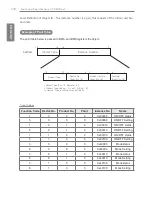
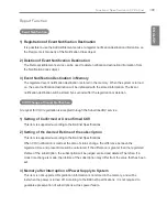
The system is designed to automatically recognize the connected air conditioners. Therefore, a 

period of approximately one minute will be required to recognize all the air conditioners after the 

system is turn on. During this period, the following error PDU may be returned when an object 

corresponding to an air conditioner is accessed.

ErrorClass = Object; ErrorCode = Unknown_Object

If an attempt is made to read the Object List property of the Device object from an air conditioner 

during the above period of recognition, the following error PDU will be returned, unless the air 

conditioner has been recognize:

ErrorClass = Device; ErrorCode = Configuration_In_Progress

Communication error response of ACP BACnet, please refer to 

ACP-BACnet Error Response 

Table on page 205

.

Clock Setting

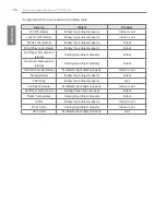
The Timesynchronization service allows clock settings by the local time.

Furthermore, the UTCTimesycchronization allows clock settings by UTC

Содержание ACP BACnet

Страница 1: ...ad the cautions for safety before installation and use and use it correctly y It is intended to keep protect the safety of the installer and user and to prevent the property damage etc y After reading the user manual please keep it at a place where user can access any time Installation User Manual MFL67709501 ...

Страница 2: ......

Страница 3: ... LG Electronics in strict adherence to the user agreement You may not reproduce or distribute by any means copies of this User Guide or any part of it without prior approval from LG Electronics Copyright 2013 LG Electronics All rights reserved Twin Towers 20 Yeouido Yeongdeungpo gu Seoul Registered Trademarks ACP BACnet is a registered trademark of LG Electronics All other products and company nam...

Страница 4: ...ii ENGLISH Explanatory Notes ...

Страница 5: ...n to cool or warm indoor air quickly in a short period of time Open windows regularly for ventilation as the indoor air quality may deteriorate if the air conditioner is used for many hours Clean the air filter once every 2 weeks Dust and impurities collected in the air filter may block the air flow or weaken the cooling dehumidifying functions Notes The product images and descriptions included in...

Страница 6: ...ENGLISH MEMO ...

Страница 7: ...l is intended for use by a qualified service technician familiar with safety procedures and equipped with the proper tools and test instruments y Failure to carefully read and follow all instructions in this manual can result in equipment malfunction property damage personal injury and or death Installation y Any question about the product installation should be asked to the service center or the ...

Страница 8: ...use fire or electric shock y You need to use a safely insulated power supply which follows IEC61558 2 6 and NEC Class2 If you do not follow It may cause fire electric shock explosion or injury y Do not connetion 220V power to 24V products If you do not follow It may cause fire electric shock explosion or injury y Do not connect power cord to the control signal connector It may cause fire or explos...

Страница 9: ...ilure of the product y Please check the operation temperature If the product is used in an environment with the temperature exceeding the operation bound ary it may cause a severe damage Please check the usage temperature boundary in the manual If there is no specified tem perature please use the product within the boundary of 0 40 C y Do not put a container etc with water on the product It may ca...

Страница 10: ...ENGLISH MEMO ...

Страница 11: ... Installing 80 Environment 97 Installing ACP BACnet 97 Installing ACP BACnet 98 Check points during the ACP BACnet installation 99 Setting the indoor unit address 101 Setting the PI485 and connecting the cable 103 Installing ACP BACnet and connecting cables 108 Setting the ACP BACnet network address 117 Setting the functions of the ACP BACnet 133LG s ACP BACnet Agreement 135Functional Specificatio...

Страница 12: ...ENGLISH MEMO ...

Страница 13: ...ajor functions of the ACP BACnet are as follows Environment setting function using the ACP BACnet external buttons ACP BACnet can use the external buttons installed outside of the ACP BACnet to set the following functions Set Network environment IP address Net mask Gateway Set the function to use between Peak demand function SW upgrade function Data backup function Data recovery function Set the I...

Страница 14: ...rious contents can be used wxjwjYYhW Internet Internet Explorer Controlling of up to 256 air conditioner indoor units Monitoring of error and operation status Controlling the peak power demand power System setting function Devices that can interface with ACP BACnet Device ACP BACnet AC Ez o Simple Central Controller o AC Smart o AC Manager o Air Conditioner o Ventilation o AWHP o Fire Alarm o Chil...

Страница 15: ...0W MAX Power Cord 250V AC 3A ACP BACnet Installation User Manual CD ACP BACnet Quick Manual www lge com P NO MFL67709511 PEFM BNF BACnet Gateway ACP BACnet PEFM P PQNFB17C1 PQNFB17C0 y Make sure to read the cautions for safety before installation and use and use it correctly y It is intended to keep protect the safety of the installer and user and to prevent the property damage etc y After reading...

Страница 16: ...4 ENGLISH ACP BACnet FUNCTIONS AND SPECIFICATION Names of each part of ACP BACnet ACP BACnet is composed as follows PQNFB17C0 PQNFB17C0 PQNFB17C0 ª PQNFB17C0 ...

Страница 17: ...nals and RS 485 communication port for external expansion 8 DI s 2 DO s 2 RS 485 communication ports RS 485 communication port RS 485 communication ports to connect to air conditioner and ventilation equipment 4 in total ª Mini USB port USB to Serial port for software debugging USB port For software update and data backup SD card slot For RS 485 communication data backup Ethernet port Ethernet por...

Страница 18: ...s y Ethernet 10 100 BASE T y USB USB Host SW upgrade data backup mini USB Device Debug y RS 485 communication ports 6EA y SD card slot RS 485 communication logging y RS 232 Console Port HMI External input output ports DI DO LED 27EA RS communication status Ethernet communication status power status operation status LCD 20 4 Character LCD network environment setting and information display Notes Li...

Страница 19: ...cted to the ACP BACnet How to Connect to the ACP BACnet is as follows 1 Connected to theACP BACnet enter the IP address of the ACP BACnet in the Internet Browser Login You can login as follows 1 Run ACP BACnet 2 After entering your ID and password in the login window click Confirm You are now logged in ...

Страница 20: ...8 ENGLISH Starting Logout You can logout as follows 1 On the top right of the ACP BACnet screen click the Logout button You are now logged out ...

Страница 21: ...ating has stopped or has already been checked Time Check the current date and time You need Internet connection to check the weather Today s Schedule y Check the registered schedules in chronological order y Click the button to move to the schedule menu Main Menu Use ACP BACnet main menu Home Return to the home screen View Menu Display the active menu Current Menu Display the name of the active me...

Страница 22: ...ENGLISH MEMO ...

Страница 23: ...een composition and features The following explains Control Monitoring screen composition and features Number Item Description Select Deselect All Select deselect all devices in a group Drawing Button View floor plans of a group Filter Button Select device types for which you want to check the control status View Type Select Select a view type for the monitoring screen Icon Simple Detailed For mor...

Страница 24: ... type Icon The control status is shown in icons The device icon has a composition and feature as follows Number Item Description Operation Mode and Device Status Icon The color at the top of the icon box shows the current operation mode and the status of the device is indicated as an icon Device Icon The device to be controlled is indicated as an icon The device shown may not represent the appeara...

Страница 25: ...eration mode are displayed only Number Item Description Operation Mode The color of the box indicates the current operation mode Device Icon The device to be controlled is indicated as an icon Details All properties of the control device are tabulated in details ...

Страница 26: ...ons Box colors and operation mode per icon Color Icon Operation Mode Blue Cooling Ventilation General Orange Heating Ventilation Electric Heat Navy Dehumidification Sky Blue Fan Green Power Saving Purple Auto Ventilation Auto Yellow ON Short Gray OFF Open Error ...

Страница 27: ...ISH Using the Program Device status icon Icon Device Status Filter Exchange Full Lock On Peak Demand Control Schedule Control device icon Icon Device Type Indoor Device Ventilators AHU AWHP Chiller DI DO DOKIT ...

Страница 28: ...d 3 Click the device you want to control To select all devices click the button at the top The device control area appears at the bottom of the screen 4 In the device control box set the control status of the device The device control box shows a different menu depending on the device For information about the control area for each device GoTo the refer to Control Menu per Device on page 17 5 Once...

Страница 29: ...et may differ depending on the model Mode y COOL Button Operates with Cooling Mode y HEAT Button Operates with Heating Mode y AUTO Button Evaluates the operating environment conditions and automatically sets the optimum temperature y DRY Button Dehumidifies during rainy seasons or whenever humidity is high You cannot set the temperature in this mode y FAN Button Purifies the air You cannot set the...

Страница 30: ... temperature y DRY Button Dehumidifies during rainy seasons or whenever humidity is high You cannot set the temperature in this mode y FAN Button Purifies the air You cannot set the temperature in this mode Fan Speed y LOW Button Slow fan speed y MED Button Medium fan speed y HIGH Button Fast fan speed y AUTO Button Loops from LOW to MEDIUM to HIGH speeds Swing y Set Button Turns on automatic osci...

Страница 31: ...unlocked Set Temp Range Click Ÿ ź to set the temperature limit 2Setpoint Button Switches between cooling and heating within the selected temperature range Indoor 2Setpoint Auto Operation Mode Item Description Auto Change Over The auto change over function works well with Heat Recovery model For other models it may not work properly Set the auto change over function to switch the operation mode aut...

Страница 32: ...atures Item Description Operation y ON Button Starts the operation of the device y Off Button Stops the operation of the device GoTo Schedule Button Move to Schedule menu Room Display the current temperature Set Temperature Click Ÿ ź to set a desired temperature the ventilator is not activated Mode y AUTO Button Evaluates the operating environment conditions and automatically sets the optimum temp...

Страница 33: ... y LOW Button Slow fan speed y HIGH Button Fast fan speed y SUPER Button Maximum fan speed y AUTO Button Loops from LOW to HIGH to SUPER speeds Partial Lock y Set Button Disables remote control for all features y Clear Button Disable the lock Additional Function y Drift Button Reduces energy consumption by operating in the most efficient method possible y Quick Button Operates at maximum performan...

Страница 34: ...mperature Click Ÿ ź to set the temperature Mode y AUTO Button Evaluates the operating environment conditions and automatically sets the optimum temperature y HEX Button Air supply and emissions are all ventilated through the heat exchanger y NORM Button Ventilate emissions without passing through the heat exchanger Fan Speed y LOW Button Slow fan speed y HIGH Button Fast fan speed y SUPER Button M...

Страница 35: ...and automatically sets the optimum temperature y HEX Button Air supply and emissions are all ventilated through the heat exchanger y NORMAL Button Ventilate emissions without passing through the heat exchanger Fan Speed y LOW Button Slow fan speed y HIGH Button Fast fan speed y SUPER Button Maximum fan speed y AUTO Button Loops from LOW to HIGH to SUPER speeds Partial Lock y Set Button Disables re...

Страница 36: ...ation y Heater On Button Enables the heater function to heat the room y Heater Off Button Disables the heater function y Humid On Button Enables the humidifier function for room humidity control y Humid Off Button Disable the humidifier function not activated Some additional function might not be provided according to your country such as U S Co Airconditioner y COOL Button Operates with Cooling M...

Страница 37: ... Mode y HEAT Button Operates with Heating Mode y FAN Button Purifies the air y DRY Button Dehumidifies the air during the rainy season or when humidity is high y Drift Button Reduces energy consumption by operating in the most efficient method possible AutoVent y Set Button If the CO2 concentration level increases during cooling or heating increase the outdoor air volume to reduce the CO2 concentr...

Страница 38: ...reases during cooling or heating increase the outdoor air volume to reduce the COǾ concentration level y Clear Button Disables AutoVent CO2 ppm 8VH Ÿ ź WR VHW WKH GHVLUHG FDUERQ GLR LGH HPLVVLRQ OHYHO IURP SSP to 1 500 ppm in intervals of 100 ppm COǾ is not settable in some models Humidify y Set Button Enables the humidifier function y Clear Button Disables the humidifier function Humidity 8VH Ÿ ź...

Страница 39: ...ON Button Starts the operation of the device y Off Button Stops the operation of the device GoTo Schedule Button Move to Schedule menu Mode y AUTO Button Evaluates the operating environment conditions and automatically sets the optimum temperature y COOL Button Operates with Cooling Mode y HEAT Button Operates with Heating Mode Air Water Temp Indicated as air or water temperature depending on the ...

Страница 40: ...ial Lock y Set Button Disables remote control for all features y Clear Button Disable the lock Mode y AUTO Button Evaluates the operating environment conditions and automatically sets the optimum temperature y COOL Button Operates with Cooling Mode y HEAT Button Operates with Heating Mode Air Water Temp Indicated as air or water temperature depending on the product Click Ÿ ź to set the air water t...

Страница 41: ...H Using the Program DO The following is the DO control menu and features Item Description Operation y SHORT Button Short signal output y OPEN Button Open signal output GoTo Schedule Button Move to Schedule menu ...

Страница 42: ...vice and device group On the floor plan you can register space information as well as the location where a device is installed 1 In the main menu click the Control Monitor menu icon 2 Select the device group you want to monitor from the group list The monitoring screen for the device is displayed 3 Click Drawing button 4 Click Edit button ...

Страница 43: ...1 ENGLISH Using the Program 5 Add Drawing button The Open Floor Plan window is displayed 6 Select a desired floor plan from the Open Floor Plan window then click Confirm The floor plan image is displayed ...

Страница 44: ...To delete a device from the plan double click its icon 8 To complete the registration of the floor plan click the Apply button Notes y To add a floor plan put image file to USB root directory or mnt flash map directory y To add a floor plan you can only use jpg gif or png file formats y To add a floor plan a 2MB or less image size is recommended ...

Страница 45: ...ou can register space information as well as the location where a device is installed 1 In the main menu click the Control Monitor menu icon 2 Select the device group you want to monitor from the group list The monitoring screen for the device is displayed 3 Click Drawing button The registered floor plan is displayed ...

Страница 46: ...ect the device group you want to monitor from the group list The monitoring screen for the device is displayed 3 Click Drawing button 4 Click Edit button 5 To change floor plan click Change button The Open Floor Plan window is displayed 6 Select a desired floor plan from the Open Floor Plan window then click Confirm The floor plan image is displayed ...

Страница 47: ...tion to which you want to move that device 8 To complete floor plan editing click the Apply button Notes y To add a floor plan put image file to USB root directory or mnt flash map directory y To add a floor plan you can only use jpg gif or png file formats y To add a floor plan a 2MB or less image size is recommended ...

Страница 48: ...l Monitor menu icon 2 Select the device group you want to monitor from the group list The monitoring screen for the device is displayed 3 Click Drawing button The registered floor plan is displayed 4 Click Edit button 5 To delete a floor plan click the Delete button 6 When you are prompted to confirm the deletion click Confirm ...

Страница 49: ...ou want to monitor from the group list The monitoring screen for the device is displayed 3 Click a device you want to monitor 4 Please check the device information in the monitoring screen The information on the monitoring screen differs depending on the view type For details about the view types View Type on page 12 5 To check the control status of the device click the Detail button ...

Страница 50: ...umption Schedule Screen composition and features The following explains Schedule Screen composition and features Number Item Description Today Button Display today s date the current week or the current month Dates y Displays the selected date y Use ೞ to move to the previous next date View Type y W Button Converts to Week View y M Button Converts to Month View Total Button View full schedule list ...

Страница 51: ...les You can configure and add a schedule for a device 1 In the main menu click Schedule menu icon 2 Add a Schedule Button The Add Schedule window opens 3 In the group list click a device for which a schedule is applied The selected device is displayed in the applied device area of the control command configuration ...

Страница 52: ...er midday Period Click the period area and then the button to select the desired period Repeat Pattern Click the Repetition Pattern area and select a desired pattern y Select Day Selected days the schedule will be performed y Once Applies a schedule once on a selected date y Everyday Applies the same schedule Everyday y Mon Fri Applies a schedule repeatedly from Monday to Friday y Mon Sat Applies ...

Страница 53: ...window for the device is displayed The control configuration window differs depending on the device 6 Configure the device control status then click the Confirm button The control list configured in the Command Summary area is displayed 7 To complete the schedule configuration click the Confirm button ...

Страница 54: ...the main menu click the Schedule menu icon 2 In the Date area click the ೞ button to select a schedule search period The number of schedules are displayed for the selected date 3 To check schedule details click a schedule you want to check in the schedule list Schedule details are displayed ...

Страница 55: ... menu click the Schedule menu icon 2 Click a schedule you wish to modify from the schedule list Schedule details are displayed 3 Click the Edit button The schedule configuration screen is displayed 4 Modify the schedule information and device control configuration then click the Confirm button The changed data will be saved ...

Страница 56: ...chedule as follows 1 In the main menu click the Schedule menu icon 2 Click a schedule you wish to delete from the schedule list Schedule details are displayed 3 Click the Delete button 4 When you are prompted to confirm the deletion click Confirm The selected schedule is deleted ...

Страница 57: ...device can operate based on that value Peak Control Peak control limits peak power consumption You can set the target operating rate so that total power consumption does not exceed the set limit To prevent power consumption from exceeding the limit the system will automatically change cooling mode to fan mode and cancel heating mode Notes Depending on the installation site specifications either of...

Страница 58: ...ck the AutoLogic Peak Control menu icons 2 Click the Edit Group button The screen converts to Edit Group 3 Click the Add Group button Notes By clicking Apply default group you can create a group automatically based on the group and indoor unit configuration set in the Device Management menu 4 When the window to input a group name is displayed enter a group name and click the Confirm button The gro...

Страница 59: ...d to the new group and click the Add button The selected device is moved to the registered device area Notes Peak control is only limited to indoor devices therefore you cannot register other devices such as the ventilator AHU or AWHP 7 To complete group creation click the Apply button ...

Страница 60: ...ws 1 In the main menu click the AutoLogic Peak Control menu icon 2 Click the Edit Group button The screen converts to Edit Group 3 In the group list click a group whose name you want to change and click the Rename button 4 Enter a new group name and click the Confirm button The group name is now changed ...

Страница 61: ...t Group 3 In the group list click a group to be deleted and click the Del Group button 4 When you are prompted to confirm the deletion click Confirm The selected group is deleted and the tab removed Notes y The group configured in Peak Control is also applied to Demand Control y If you change the group configuration in the device management menu the group configured in Peak Control is initialized ...

Страница 62: ...tus in the control configuration area Number Item Description Group List Displays the device group list and group priority Control Configuration Area Configures Peak Control configuration and details y Operation Status Can be configured in Environment Advance Setting Priority Control Control based on group priority Outdoor Unit Control Controls based on outdoor unit capacity limit ...

Страница 63: ...o switch over y Target ratio Click Ÿ ź or drag to set the target rate y Current Running Displays the current rate Operation Status Outdoor unit capacity control selected y Operation Run Button Operates the device Stop Button Stops the operation of the device y Target ratio Click Ÿ ź or drag to set the target rate Edit Group Button Edit a control group Cancel Button Cancels control configuration Ap...

Страница 64: ... click the AutoLogic Peak Control menu icon 2 In the group list click the priority icon of the group in question and then select a desired priority Notes Basically a newly added group has the highest priority If a group is added re configure the priority for all groups ...

Страница 65: ... Using the Program Checking Peak Control Status You can check the Peak Control configuration status as follows 1 In the main menu click the AutoLogic Peak Control menu icon 2 Check how Peak Control is configured ...

Страница 66: ... Operation Status Priority Control selected y Operation Run Button Operates the device Stop Button Stops the operation of the device y ShiftTime Min The cycle by which the operation switches over y Target ratio Displays the target operation rate y Current Running Displays the current rate Operation Status Outdoor unit capacity control selected y Operation Run Button Operates the device Stop Button...

Страница 67: ... Control is configured Number Item Description Comm Status with Demand Controller Displays the communication status between demand controller and ACP BACnet Control Configuration Area Checks the demand configuration details y Operation Status Can be configured in Environment Advance Setting Priority Control Control based on group priority Outdoor Unit Control Controls based on outdoor unit capacit...

Страница 68: ...tops the operation of the device y Shift Time Min The cycle by which the operation switches over y Target ratio Displays the target operation rate y Current Running Displays the current rate Operation Status Outdoor unit capacity control selected y Operation Run Button Operates the device Stop Button Stops the operation of the device y Target ratio Displays the target operation rate ...

Страница 69: ...s them by group The following explains how to create groups and how to edit the created groups Adding Groups You can create a group as follows 1 In the main menu click the AutoLogic TimeLimitControl menu icon 2 Click the Edit Group button The screen converts to Edit Group 3 Click the Add Group button Notes By clicking Apply default group you can create a group automatically based on the group and ...

Страница 70: ... Step 4 6 In the non registered device area click a device to add to the new group and click Add button The selected device is moved to the registered device area Notes For the time limit operation you cannot register DI DO 7 To complete group creation click the Apply button ...

Страница 71: ... 1 In the main menu click the AutoLogic TimeLimitControl menu icon 2 Click the Edit Group button The screen converts to Edit Group 3 In the group list click a group whose name you want to change and click the Rename button 4 Enter a new group name and click the Confirm button The group name is now changed ...

Страница 72: ...lick the AutoLogic TimeLimitControl menu icon 2 Click the Edit Group button The screen converts to Edit Group 3 In the group list click a group to be deleted and click the Del Group button 4 When you are prompted to confirm the deletion click Confirm The selected group is deleted and the tab removed ...

Страница 73: ... group are displayed 3 Select the control status in the conditions configuration area Item Description Oper Choosing whether to run Time Limit Operation y Run Button Run the time limit operation y Stop Button Stops the time limit operation Hours to Off Hour y Select the operation time limit of an operation group y The devices included in the group operates for the selected time then stops automati...

Страница 74: ...n on the group in the group configuration operation status area click the disable button The button changes to enable 5 To complete the configuration click the Apply button Notes If you change the operation stop standby time it takes about 15 seconds to apply it ...

Страница 75: ... explains how to create and manage a pattern and control device integration Managing Pattern The following explains how to register integrated devices as a pattern and how to modify or delete a registered pattern Adding Pattern You can add a pattern as follows 1 In the main menu click the AutoLogic InterLocking menu icon 2 Click the Add button A window to create a pattern is displayed 3 Type a new...

Страница 76: ...control 7 Select a control status in the control configuration area 8 Click the Output Device tab 9 In the non registered device area click a device to be registered and click the Add button 10 In the output device list click the device you want to control 11 Select a control status in the control configuration area 12 To complete the adding of a pattern click the Apply button ...

Страница 77: ... button The pattern editing screen opens 3 Modify the pattern configuration information and click the Apply button Deleting Pattern You can delete a pattern as follows 1 In the main menu click the AutoLogic InterLocking menu icon 2 Select a pattern to be deleted and click the Delete button 3 When you are prompted to confirm the deletion click OK The selected pattern is deleted ...

Страница 78: ...he Program Checking InterLocking 1 In the main menu click the AutoLogic InterLocking menu icon 2 Click a pattern for which you want check the device integration The device integration status for the pattern is displayed ...

Страница 79: ...ion and features Number Item Description Group List Displays the device group list Statistics Items y Power Button You can check the power consumption of each group and total power consumption y RunTime Button You can check the operating time and the total operating time of indoor units in each group Query Unit y Monthly Button Queries on monthly consumption within the last four months y Daily But...

Страница 80: ...Button y Selects Statistics Reference Date y Move to Settings General Settings Statistics Reference Date Querying Statistics You can query the power consumption of a device or operation time statistics data as follows 1 In the main menu click the Statistics menu icon 2 Click the device group you want from the group list 3 Click the button of the statistics item you want Power Button You can check ...

Страница 81: ...n view type click the Table or Graphic button Notes The statistics data is stored up to 6 months Notes y Devices which can query the Run Time Indoor units y Devices which can query the Power consumption devices which can be used with the PDI For further information about the devices can be used with the PDI please refer to the PDI manual ...

Страница 82: ...port query items y Total Button Queries all reports regarding control and error y Control Button Queries control related reports only y Error Button Queries error related reports only Query Period Selection Area y Selects the period for which you want to query report details y The starting date should be no more than three months from the ending date Report detail display area Displays the reports...

Страница 83: ... all reports regarding control and error Control Button Queries control related reports only Error Button Queries error related reports only 3 In the query period selection area click the date button and button to select the desired period The starting date should be no more than three months from the ending date 4 Check the report details in the report detail display area Caution You can query up...

Страница 84: ...ically Registering Device Manually Notes To register a device on ACP BACnet you should login with administrator permissions If you have logged in already with standard user permissions you cannot proceed with this process any further Registering Device Automatically Devices connected to ACP BACnet are automatically searched for and registered You can register a device automatically as follows 1 In...

Страница 85: ... prompted to confirm the setting click Confirm It takes 5 to 10 minutes to register a device automatically 5 To save the searched devices touch the Apply button Device registration is completed 2 DIs and 2 DOs is always added to the Unit Status ...

Страница 86: ...ansion Energy Recovery Ventilator DI DO DOKIT AWHP or AHU Unit Name 20 Characters Enter the device name y Up to 20 characters Address 00 FF Type the physical address of the device y A physical address value is a number between 00 and FF You cannot type the same value for the same device y You cannot enter a duplicate value for indoor devices and DOKIT Model 20 Characters Type the device model y Up...

Страница 87: ...evice information and click the Modify Unit button The changed device information is applied 5 To save a change click the Apply button Deleting Device Follow these steps to delete a device from the list 1 In the main menu click the Installing menu icon 2 Click the Installing tab 3 In the device list click a device to be deleted and click the Del Unit button 4 When you are prompted to confirm the d...

Страница 88: ...ing Groups Follow these steps to add a new group 1 In the main menu click the Installing menu icon 2 Click the Grouping tab 3 Click the Add Group button 4 When the window to type a group name is displayed enter a group name and click the Confirm button The group is added to the group list 5 In Grouping click the group added in Step 4 ...

Страница 89: ...ice area click a device to add to the new group and click the Add button The selected device is moved to the registered device area 7 To complete group creation click the Apply button When all non registered devices are registered the Apply button is enabled ...

Страница 90: ...istered group as follows 1 In the main menu click the Installing menu icon 2 Click the Grouping tab 3 In the device management list click a group whose name you want to change and click the Rename button 4 Enter a new group name and click the Confirm button The group name is changed ...

Страница 91: ...p 1 In the main menu click the Installing menu icon 2 Click the Grouping tab 3 In the device management list click a group to be deleted and click the Del Group button 4 When you are prompted to confirm the deletion click Confirm The selected group is deleted and the tab removed ...

Страница 92: ...nfigures the language displayed on the screen ଞ Korean English Time setting Configures system time Date setting Configures system date Temperature display Configures the temperature system Initial date for statistics Configures the reference date for querying statistical data Rates per 1kWh Configures the charge per 1kWh and currency Holiday setting The day schedule is not work Selects the days fo...

Страница 93: ...ck a language you want The selected language is applied as the system language Time setting You can configure the time used for the system as follows 1 In the main menu click the Environment menu icon 2 In the Settings list click General Setting 3 In the detailed settings list click Time setting 4 Apply the current time and click the Apply button Click button to select the time Click the AM PM but...

Страница 94: ...e pattern configuration information and click the Apply button Use button to select a date Temperature display You can select a temperature system as follows 1 In the main menu click the Environment menu icon 2 In the Settings list click General Setting 3 In the detailed settings list click Temperature display 4 Click the temperature system you want When selecting the Celsius system in the Minimum...

Страница 95: ... the Environment menu icon 2 In the Settings list click General Setting 3 In the detailed settings list click Initial date for statistics 4 button to select a date you want and Apply button Rates per 1kWh You can configure the charge per kWh and the currency as follows 1 In the main menu click the Environment menu icon 2 In the Settings list click General Setting 3 In the detailed settings list cl...

Страница 96: ...ent menu icon 2 In the Settings list click General Setting 3 In the detailed settings list touch Holiday setting Days in which the schedule is ignored The Exception Date Configuration window opens 4 Type a name for the exception date in the exception date input box 5 button to select an exception date 6 To add the selected exception date click Add The exception date is registered on the exception ...

Страница 97: ...d The Exception Date Configuration window opens 4 Click an exception date in the exception date list and click the Delete button 5 To complete Exception Date Configuration click the Apply button Version Information You can check the current version of the software as follows 1 In the main menu click the Environment menu icon 2 In the Settings list click General Setting 3 In the detailed settings l...

Страница 98: ...ture in the auto logic menu Set the operation mode y Priority Control In Peak Demand Control menu control the devices based on the priority of the group y Outdoor Unit Capacity Control In the Peak Demand Control menu control the outdoor capacity rate per unit Temperature difference for Setback AutoChangeOver button to select the temperature gap Update S W y Software upgrade using a USB memory stic...

Страница 99: ...k LGAP setting 4 Click a type you want Master ACP BACnet must be set to only master Slave Not used Peak Demand set You can select a control type to be used for auto logic 1 In the main menu click the Environment menu icon 2 In the Settings list click Advance Setting 3 In the detailed settings list click Peak Demand set 4 Click a control type to be used for auto logic Peak Control You can use the p...

Страница 100: ... click Set the operation mode 4 Click an operation type you want Temperature difference for Setback AutoChangeOver You can configure the temperature gap for auto changeover operation 1 In the main menu click the Environment menu icon 2 In the Settings list click Advance Setting 3 In the detailed settings list click Temperature difference for Setback AutoChangeOver 4 button to select a temperature ...

Страница 101: ... which has patch tar file in the ramdisk folder 1 Connect the USB memory to ACP BACnet 2 In the main menu click the Environment menu icon 3 In the Settings list click Advance Setting 4 In the detailed settings list click Update S W 5 When the software update window appears click the Update S W button When the update has been completed the program restarts ...

Страница 102: ...ick DB backup 5 When the DB Backup window appears click the DB backup button Recovery DB You can use the database stored on USB memory to restore the system database 1 Connect the USB memory stick to ACP BACnet 2 In the main menu click the Environment menu icon 3 In the Settings list click Advance Setting 4 In the detailed settings list click Recovery DB 5 When the DB Recovery window appears click...

Страница 103: ...inistrator account can change user environments Item Description Change Password Only the administrator account can change the password Add user Add up to 30 new system users User Management y Delete Button Deletes a user y Edit Button Changes user information ...

Страница 104: ...nu icon 2 In the Settings list click Customer Setting 3 In the detailed settings list click Change Password 4 After entering the current and new passwords click Confirm Current P W Enter the current password New P W Enter the new password a user desires Re type P W Enter the new password to confirm that the new password has been entered correctly ...

Страница 105: ...d and click Confirm 5 When the Add a New User window appears enter the user information and click Confirm ID Enter the user s ID for the email server Password Enter the login password Password Confirm Re enter the password User Role Select the user permission you want Accessable Group Select a controllable device group Notes Use is limited depending on the user y General user menu auto logic repor...

Страница 106: ...ered user s information as follows 1 In the main menu click the Environment menu icon 2 In the Settings list click Customer Setting 3 In the user list click the Delete button for the user information you want to delete 4 When the system password input window appears enter the password and click Confirm The user information is deleted 5 To complete user delete click Confirm ...

Страница 107: ... s information as follows 1 In the main menu click the Environment menu icon 2 In the Settings list click Customer Setting 3 In the user list click the Edit button for the user information you want to edit 4 When the system password input window appears enter the password click Confirm ...

Страница 108: ...96 ENGLISH Using the Program 5 When the Edit User window appears enter the user information and click Confirm The updated user information is applied 6 To complete user edit click Confirm ...

Страница 109: ...P 4 Set PI485 and connect cables Set DIP switch of PI485 correctly and connect RS 485 communication cable STEP 5 Install ACP BACnet and connect cables Install the ACP BACnet and set network and other settings STEP 6 Set ACP BACnet network address Set the network address to be able to access the ACP BACnet through internet STEP 7 Set ACP BACnet functions Set language peak demand whether to use sche...

Страница 110: ...ACnet One ACP BACnet can be connected up to 256 indoor units To one RS 485 port all of 256 indoor units which is the maximum number that can be connected to the ACP BACnet may be connected But to improve the communication performance of RS 485 it is recommended to be divided and connected to 4 ports RS 485 communication cable connection There is a polarity in RS 485 communication cable connection ...

Страница 111: ...door unit address Notes Assigning indoor and outdoor unit number If the outdoor unit product is Multi V it is recommended to assign the address by setting the first digit of the address as the number of the outdoor unit and classifying the second digit as the number or the indoor unit for easy composition and classification of the system The following example sets the address to the indoor unit BA...

Страница 112: ...he example that sets the addresses of 30 and 31 to the ventilators and connects to the ACP BACnet Notes How to set the central control address of the indoor unit The central control address setting method may be different for each indoor unit product or remote control type so set the address by referring to the manual of the indoor unit product or wired remote controller ...

Страница 113: ...PI485 by referring to the PI485 manual or the installation technique information To connect PI485 and the ACP BACnet two RS 485 cables need to be connected to BUS A and BUS B of PI485 Connect RS 485 cable by referring to the following figure XW nuk i z h i z i nuk nu nu nu nu nu nu nu nu u nu n n n n n n n n n n i z h i z i i i i i i i i i i i i i i i i i i i If several PI485 are connected to each...

Страница 114: ...102 ENGLISH Installing ACP BACnet The following figure is an example of connecting several PI485 with each other to connect to one ACP BACnet PQNFB17C0 ...

Страница 115: ...e place and RS 485 cable shall be connected for the communication with PI485 And Ethernet cable LAN cable shall be connected for the connection with internet or AC Manager To fix the ACP BACnet the following 2 methods may be used Install in DIN RAIL or fix to the wall considering the environment of the site PQNFB17C0 Power LAN cable RS 485 cable ...

Страница 116: ...the ACP BACnet Before installing the ACP BACnet check if it is the adequate place to connect the ACP BACnet with the power RS 485 and LAN cable Install DIN RAIL Hook the top part of the ACP BACnet on DIN RAIL Push the main body of the ACP BACnet until you hear the sound of installation Pull the ACP BACnet to check if it is fixed Hooking on DIN RAIL Fixing to DIN RAIL Caution y After installing to ...

Страница 117: ...re according to the location to install PQNFB17C0 Connecting RS 485 cable to the ACP BACnet After fixing the ACP BACnet in the installation place RS 485 cable that was connected to PI485 shall be connected to the ACP BACnet To connect RS 485 cable to the ACP BACnet proceed as the following order First among the connectors that can be connected to the ACP BACnet connect the end of RS 485 cable conn...

Страница 118: ...nit connections shall be appropriately connected to CH1 to CH4 in BUS format Otherwise the ACP BACnet may malfunction The following is an example of dividing to CH1 and CH2 and connecting in BUS format PQNFB17C0 BACnet The next shows the wrong example STAR connection of RS 485 connection of the ACP BACnet PQNFB17C0 BACnet Caution If a different type of connection is made other than BUS format as i...

Страница 119: ...cted as a direct cable Use Ethernet cable direct cable to connect to LAN port of the ACP BACnet Connecting ACP BACnet and PC It is the case of installing AC Manager in a separate PC and connecting ACP BACnet and PC directly In such case Ethernet cable shall be connected as a cross cable Use Ethernet cable cross cable to connect to LAN port of the ACP BACnet ଭ ʹࠆ ࠧٮ Ьࢇԧઝ ৼࢇ ٴ CPCIGT 2NWUɹ ۳ Ѷ 2 ࠧ ऍ...

Страница 120: ...e network environment information If the above information is not entered the communication error may be occurred or it may be impossible to control by the ACP BACnet So be careful to correctly input Before configuring the ACP BACnet environment The network environment of the ACP BACnet can be set by the LCD and the buttons at the front side of the ACP BACnet The current ACP BACnet information and...

Страница 121: ...BACnet booting screen is displayed on the LCD as shown at the following figure and when booting is completed the initial ACP BACnet screen is displayed 1 OFU Notes Software version The software version of the current ACP BACnet is displayed at the initial ACP BACnet screen Also the software version may be different according to the manufacturing date of the ACP BACnet 1 OFU ...

Страница 122: ...the following figure In Contents menu you can set the functions of the ACP BACnet and select language to use When you select Function and press SET button it enters the No 3 menu in the following figure In Function menu ACP BACnet software service function is supported When you select Register FD and press SET button it enters the No 4 menu in the following figure For more information please consu...

Страница 123: ... the ACP BACnet How to set network address Q 1HWZRUN QIR PHQX XVH WKH FDWHJRU WR VHW XVLQJ XS DQG GRZQ Ÿ ź EXWWRQV 3 DWHZD DQG 1HW PDVN VHWWLQJV DUH GLVSOD HG LQ WKH LQLWLDO VFUHHQ RI 1HWZRUN QIR PHQX DQG RX FDQ FKHFN 0 DGGUHVV DQG 3 VHWWLQJ XVLQJ GRZQ ź EXWWRQ DOWN UP To change the network setting locate the arrow on the corresponding setting position and press SET button to enter the correspondi...

Страница 124: ...QJ GRZQ ź EXWWRQ DPSOH RI SUHVVLQJ ULJKW Ź EXWWRQ Click GRZQ ź button Click ULJKW Ź button Caution Setting the network address y The network address can be separated to 4 digits based on and each number shall be 255 or less y Number exceeding 255 may not be input Notes Assigning the network address y Network address shall be assigned by the person in charge of the network of the corresponding site...

Страница 125: ...ollowing menu screen will be displayed If you press SET button again Network Info setting screen will be displayed While IP is selected pressing SET button will display the screen to input IP address Network Info IP GW MS 000 000 000 000 000 000 000 000 000 000 000 000 Set IP Address 000 000 000 000 Network Info Contents Function Register FD 6 7 ટ պ 6 7 ટ պ Click SET button Click SET button 2 8VH ...

Страница 126: ...s Function Register FD Set DHCP Not 0 USE 1 0 Network Info MC DHCP NO 000000 00 00 00 6 7 ટ պ Ɂ ટ ό ء պ 6 7 ટ պ Click SET button Click SET button Click ź EXWWRQ four times 2 8VH XS DQG GRZQ Ÿ ź EXWWRQV WR VHW ZKHWKHU WR XVH 3 IXQFWLRQ KHQ RX SUHVV XS Ÿ EXWWRQ 3 IXQFWLRQ LV VHW WR XVH DQG LI GRZQ ź EXWWRQ LV pressed DHCP is set for no use 3 To use dynamic IP set to use DHCP function 1 1 Set DHCP No...

Страница 127: ...erly done You can check the possibility of accessing the ACP BACnet through PING test 1 You can open the following DOS window through Windows Start Run cmd input 2 In DOS screen input ping ACP BACnet IP address as follows to run PING test When the network setting is properly done When the network setting is not properly done ...

Страница 128: ...le Notes When PC and ACP BACnet are connected together in a hub or a switch hub and you cannot access the ACP BACnet y If it is right after changing the IP setting of the ACP BACnet reset the power of the ACP BACnet y If it is right after connecting LAN cable to the hub or switch it may take time for the hub or the switch to recognize the ACP BACnet In such case it may help to turn off and turn on...

Страница 129: ...devices such as AC Manager power distribution indicator and Demand controller In general the function of the ACP BACnet should be set and used as follows When only ACP BACnet is used When ACP BACnet interfaces with AC Manager Peak or demand selection function Set to peak function Set to demand function Schedule function Set to use schedule function Set to no use of schedule function Power display ...

Страница 130: ...ge operation ratio in the ACP BACnet Demand It is set when it interfaces with AC Manager When this function is set the maximum usage operation ratio can be set in AC Manager to manage the maximum power consumption of the air conditioner One of these two methods can be selected and used in the ACP BACnet And if it is set by the menu of the ACP BACnet the UI screen is differently displayed when acce...

Страница 131: ...tton will display the screen to select peak or demand method Network Info Contents Function Register FD Set PeakDemand PK 0 DMD 1 0 Contents Peak Demand Language Schedule 0 0 0 6 7 ટ պ 6 7 ટ պ Click SET button Click SET button 2 8VH XS DQG GRZQ Ÿ ź EXWWRQV WR VHW WKH GHVLUHG SRZHU PDQDJHPHQW PHWKRG I RX SUHVV XS Ÿ EXWWRQ LW LV VHW WR GHPDQG PHWKRG DQG LI RX SUHVV GRZQ ź EXWWRQ LW LV VHW WR SHDN PH...

Страница 132: ...tion fire sensor needs to be connected to ACP BACnet DI1 y Please refer to each fire sensor product manual for detail usage of fire sensors Network Info Contents Function Register FD Set FireAlarm NOT 0 USE 1 0 Contents FireAlarm 0 6 7 ટ պ 6 7 ટ պ Click SET button Click SET button 1 When you press the SET button of the ACP BACnet menu screen will be displayed 8VH XS DQG GRZQ Ÿ ź EXWWRQV WR VHOHFW ...

Страница 133: ...ain While CH6 USAGE is selected if you press SET button you can select one from D Demand or M Modbus Network Info Contents Function Register FD Set CH6 USAGE Demand Modbus D Contents CH6 USAGE D 6 7 ટ պ 6 7 ટ պ Click SET button Click SET button Software service function The following software service function can be run using the menu of the ACP BACnet This function shall only be used by the speci...

Страница 134: ... the specialized service technician Software update can be done with USB memory Proceed in the following order 1 UHDWH UDPGLVN IROGHU LQ 86 PHPRU 2 3XW WKH 6 ILOH WR XSGDWH LQ ƍUDPGLVNƍ IROGHU At this time only one S W file must be put New version software file can be downloaded from LG Electronics System Air Conditioner homepage ...

Страница 135: ...123 ENGLISH Installing ACP BACnet E may be changed ...

Страница 136: ...ot immediately restart update will be applied only after rebooting the ACP BACnet in the future Network Info Contents Function Register FD Function S W update DB back up DB recover S W update SET Yes ESC No Completed Restart now SET Yes ESC No Please wait 6 7 ટ պ 6 7 ટ պ 6 7 ટ պ a ট о Click SET button Click SET button Click SET button Wait for S10 20 sec Caution KLOH VRIWZDUH XSGDWH LV LQ SURJUHVV...

Страница 137: ... backup is necessary it must be carried out by the specialized service technician Data backup can be done with USB memory or SD card Proceed in the following or der 1 Insert USB memory or SD card into the ACP BACnet Refer to software update for USB memory insertion ...

Страница 138: ... remove USB memory 86 ֻչ ӖЕ 6 FDUG ࢿʠ Network Info Contents Function Register FD DB back up USB SD card Function S W update DB back up DB recover Completed Remove USB or SD card 6 7 ટ պ 6 7 ટ պ 6 7 ટ պ Click SET button Click SET button Click SET button Remove USB memory or SD card Caution Before data backup is completed turning off the power of the ACP BACnet or removing USB memory or SD card may ...

Страница 139: ... recovery is necessary it must be carried out by the specialized service technician Data recovery can be done with USB memory or SD card Proceed in the following order 1 Save the database file to recover in USB memory or SD card 6DYH WKH ILOHV LQ GE IROGHU DV IROORZV ...

Страница 140: ...ter completing the data recovery ACP BACnet is automatically restarted for data recovery Caution Before data recovery is completed turning off the power of the ACP BACnet or removing USB memory or SD card may cause severe disorder of the ACP BACnet Network Info Contents Function Register FD DB recover USB SD card Function S W update DB back up DB recover Completed Remove USB or SD card Completed A...

Страница 141: ...rt SD card into the ACP BACnet Refer to data backup 2 Press SET button of the ACP BACnet 3 Select Function menu and press SET button 4 Select Data Logging menu and press SET button again 5 Select whether to set data logging Network Info Contents Function Register FD Function Data Logging Function S W update DB back up DB recover Set Data Logging Not 0 USE 1 0 6 7 ટ պ 6 7 ટ պ ଜ Ɂ ટ պ Click SET butt...

Страница 142: ...e Foreign Device setting locate the arrow on the corresponding setting position and press SET button to enter the corresponding setting screen Example of IP setting Network Info Contents Function Register FD Set FD IP 192 168 000 000 Register FD IP 000 000 000 PORT 00000 TTL 00000 ON 0 6 7 ટ պ 6 7 ટ պ Example of PORT setting Network Info Contents Function Register FD Set FD PORT 047808 Register FD...

Страница 143: ...00000 TTL 00000 ON 0 6 7 ટ պ 6 7 ટ պ Example of Foreign Device Activate setting Network Info Contents Function Register FD Set FD ACTIVATE NOT 0 USE 1 0 Register FD IP 000 000 000 PORT 00000 TTL 00000 ON 0 6 7 ટ պ 6 7 ટ պ Notes For more information please consult with the experts of BMS Click SET button Click SET button Click SET button Click SET button ...

Страница 144: ...ENGLISH MEMO ...

Страница 145: ...D s prior to connection with the BMS system BMS Engineering Creating of the Points This is NOT to be done by LG since it is directly related to the BMS side The BMS engineer is to carry out the engineering of the Point however LG is responsible for providing the method of how the Points are calculated Commission First step only using LG s ACP BACnet without connecting BMS This is to be carried out...

Страница 146: ...otes After the LG s ACP BACnet agreement part please consult with the experts of BMS PQNFB17C0 Hub BACnet LG NET ACP BACnet Diagnosis 1 Creating of indoor and vent points 2 Test of all units and operations 06 QJLQHHULQJ 6LGH QJLQHHULQJ 6LGH ...

Страница 147: ...ormation of A C vent that are connected to the ACP BACnet s internal LG NET will be sent in BACnet service form and BACnet client provides a function that transmits control command to the A C vent system Configuration of Connection A BACnet client that supports BACnet ANSI ASHRAE135 protocol allows direct connection via generally used HUBs or Ethernet The image of its connection configuration is a...

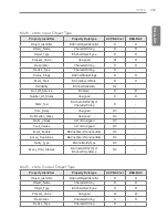
Страница 148: ...Permit Prohibit 4 Lock Status LockStatus_XXX BI Permit Prohibit 5 Filter Sign Filter Sign_XXX BI Off On 6 Filter Sign Reset Filter Sign Reset_ XXX BV Reset 7 Operation Mode Setting ModeCommand_XXX MO Cool Dry Fan Auto Heat 8 Operation Mode Status ModeStatus_XXX MI Cool Dry Fan Auto Heat Swing Setting SwingCommand_ XXX BO Stop Run 10 Swing Status SwingStatus_XXX BI Stop Run 11 Fan Speed Setting Fan...

Страница 149: ...n AccumPowerStatus_ XXX AI Wattage values Unit 100Watt 27 Set Upper Temperature Setting SetUpperTempCom mand_XXX AV C 28 Set Lower Temperature Setting SetLowerTempCom mand_XXX AI C Set Upper Temperature Status SetUpperTempSta tus_XXX AI C 30 Set Lower Temperature Status SetLowerTempSta tus_XXX AI C 31 Mode Lock Setting ModeLockCom mand_XXX BO Permit Prohibit 32 Mode Lock Status ModeLockStatus_ XXX...

Страница 150: ... Status StartStopStatus_XXX BI Stop Run 3 Lock Setting LockCommand_XXX BO Permit Prohibit 4 Lock Status LockStatus_XXX BI Permit Prohibit 5 Filter Sign Filter Sign_XXX BI Off On 6 Filter Sign Reset Filter Sign Reset_ XXX BV Reset 7 Operation Mode Setting ModeCommand_XXX MO Heat Exchange Auto Normal 8 Operation Mode Status ModeStatus_XXX MI Heat Exchange Auto Normal 10 11 Fan Speed Setting FanSpeed...

Страница 151: ...UserModeCom mand_XXX MO Quick Fresh Energy Saving Heater 18 User Mode Status UserModeStatus_ XXX MI Quick Fresh Energy Saving Heater C 20 21 AC Operation Mode setting HrvModeCommand_ XXX MO Cool Auto Heat 22 AC Operation Mode status HrvModeStatus_XXX MI Cool Auto Heat 23 AC ON OFF setting HrvStartStopCom mand_XXX BO Stop Run 24 AC ON OFF status HrvStartStopStatus_ XXX BI Stop Run 25 AC Humidify se...

Страница 152: ...us StartStopStatus_XXX BI Stop Run Lock Setting LockCommand_XXX BO Permit Prohibit Lock Status LockStatus_XXX BI Permit Prohibit Filter Sign Filter Sign_XXX BI Off On Filter Sign Reset Filter Sign Reset_XXX BV Reset Operation Mode Setting ModeCommand_XXX MO Cool Dry Fan Heat Operation Mode Status ModeStatus_XXX MI Cool Dry Fan Heat Set Room Temperature SetRoomTemp_XXX AV C Room Temperature RoomTem...

Страница 153: ...umidifyStatus_XXX BI 6WRS Run 26 Auto Ventilation Setting AutoVentil Command_XXX BO 6WRS Run 27 Auto Ventilation Status AutoVentilStatus_XXX BI 6WRS Run 28 Supply Temperature Status SupplyTempStatus_XXX AI 127 127 Outdoor Temperature Status OutdoorTempStatus_XXX AI 127 127 30 Mix Temperature Status MixTempStatus_XXX AI 127 127 31 Supply Humidity Status SuppyHumidify Status_XXX AI a 32 Outdoor Humi...

Страница 154: ...WXVB 6WRS 5XQ XUUHQW 2 DPSHU 6WDWXV XU2 DPSHU 6WDWXVB a XUUHQW DPSHU 6WDWXV XU DPSHU 6WDWXVB a XUUHQW 0 DPSHU 6WDWXV XU0L DPSHU6WDWXVB a RRO 2 DPSHU 6HWWLQJ 2 DPSHU RRO RPPDQGB 9 a Cool OA Damper Status 2 DPSHU RRO6WDWXVB a Cool EA Damper Setting DPSHU RRO RPPDQGB 9 a Cool EA Damper Status DPSHU RRO6WDWXVB a Cool MIX Damper Setting MixDamperCoolCommand_ XXX 9 a Cool MIX Damper Status MixDamperCool...

Страница 155: ...r Setting DPSHU HDW RPPDQGB 9 a 51 Heat EA Damper Status DPSHU HDW6WDWXVB a 52 Heat MIX Damper Setting 0L DPSHU HDW RPPDQGB 9 a 53 Heat MIX Damper Status 0L DPSHU HDW6WDWXVB a 54 Fan OA Damper Setting 2 DPSHU 1 RPPDQGB 9 a 55 Fan OA Damper Status 2 DPSHU 16WDWXVB a 56 Fan EA Damper Setting D P S H U 1 R P P D Q G B 9 a 57 Fan EA Damper Status DPSHU 16WDWXVB a 58 Fan MIX Damper Setting 0L DPSHU 1 R...

Страница 156: ...144 ENGLISH Functional Specifications ACP BACnet ...

Страница 157: ...ommand_XXX BO Stop Run 4 Lock status LockStatus_XXX BI Stop Run 5 Operation Mode setting ModeCommand_XXX MO Cool HDW XWR 6 Operation Mode status ModeStatus_XXX MI Cool HDW XWR 7 Set Room Temperature setting SetRoomTempCom mand_XXX AO Ȕ 8 Set Room Temperature status SetRoomTempSta tus_XXX AI Ȕ Set Hot Water Temperature setting SetHotWaterTemp Command_XXX AO Ȕ 10 Set Hot Water Temperature status Set...

Страница 158: ...rmal Hot Water Only 15 Current Room Temperature RoomTemp_XXX AI Ȕ 16 Alarm Event Alarm_XXX BI No error Error 17 Malfunction Code MalfunctionCode_ XXX AI Reference LG Original Error Code 18 HotWater On Off setting HotWaterCommand_ XXX BO Ȕ HotWater On Off status HotWaterStatus_XXX BI Ȕ 20 Pipe Inlet Temperature Status PipeInTempSta tus_XXX AI Ȕ 21 Water Tank Temperature Status TankTempStatus_ XXX A...

Страница 159: ...s 16EA Device No Product Unit No Point No Instance Number Example of Point Table The point table below is passed to BMS and BMS registers the object Case Indoor Address Object Type Device No Product No Point Instance No Name Ő 21 2 VHWWLQJ Ő 21 2 VWDWXV Ő 21 2 VHWWLQJ Ő 21 2 VWDWXV Ő 21 2 VHWWLQJ Ő 21 2 VWDWXV Ő 21 2 VHWWLQJ Ő 21 2 VWDWXV Ő 21 2 VHWWLQJ Ő 21 2 VWDWXV Ő 21 2 VHWWLQJ Ő 21 2 VWDWXV Ő...

Страница 160: ...Name Ő 21 2 VHWWLQJ Ő 21 2 VWDWXV Ő 21 2 VHWWLQJ Ő 21 2 VWDWXV Ő 21 2 VHWWLQJ Ő 21 2 VWDWXV Ő 21 2 VHWWLQJ Ő 21 2 VWDWXV Ő 21 2 VHWWLQJ Ő 21 2 VWDWXV Ő 21 2 VHWWLQJ Ő 21 2 VWDWXV Ő 21 2 VHWWLQJ Ő 21 2 VWDWXV Ő 21 2 VHWWLQJ 21 2 VWDWXV Ő 21 2 VHWWLQJ Ő 21 2 VWDWXV Case AHU Address Object Type Device No Product No Point Instance No Name 21 2 VHWWLQJ 21 2 VWDWXV 21 2 VHWWLQJ 21 2 VWDWXV 21 2 VHWWLQJ ...

Страница 161: ...Present_ Value Property will be read in a value immediately before the communication error Run Stop Setting Point number 1 Object name StartStopCommand_XXX XXX Indoor Vent AHU address Object type Binary Output Meaning This object is used to give Run Stop commands to the air conditioner Present_Value property ACTIVE Run command INACTIVE Stop command Remarks 1 The command executed is transmitted to ...

Страница 162: ...t Meaning This object is used to monitor the Lock of the A C s control authority Present_Value property ACTIVE Lock Restricted INACTIVE Unlock Not restricted Filter Sign Point number 5 Object name FilterSign_XXX XXX Vent AHU address Object type Binary Input Meaning This object is used to monitor the status of the filters for vent Present_Value property ACTIVE Filter sign information is turned ON I...

Страница 163: ...itten 3 This object supports the Intrinsic Reporting function When the Present_Value property changes the corresponding Event will be transmitted if the Event has been registered Operation Mode Setting Point number 7 Object name ModeCommand_XXX XXX Indoor Vent AHU address Object type Multistate Output Meaning This object is used to set the operation modes of the air conditioner Present_Value prope...

Страница 164: ...1 Cool HEX 2 Dry Auto 3 Fan Normal 4 Auto 5 Heat Swing Setting 3RLQW QXPEHU Object name SwingCommand_XXX XXX Indoor address Object type Binary Output Meaning This object is to set the air direction of the indoor unit Present_Value property ACTIVE Run INACTIVE Stop Swing Status Point number 10 Object name SwingStatus_XXX XXX Indoor address Object type Binary Input Meaning This object is to monitor ...

Страница 165: ...gard the command which the object which can t select the operation mode Therefore controlled monitored system shouldn t use the object which can t select the operation mode Fan Speed Status Point number 12 Object name FanSpeedStatus_XXX XXX Indoor Vent addresss Object type Multistate Input Meaning This object is to monitor the airflow of the A C Present_Value property PFQQT 8GPV 1 Low Low 2 Middle...

Страница 166: ...l be reported the moment a temperature change of at least 1 C is detected Room Temperature Point number 14 Object name RoomTemp_XXX XXX Indoor AHU address Object type Analog Input Meaning This object is used to monitor room temperature which the indoor unit is placed Present_Value property Temperature C Remarks This object is for indoor units only and reports the room temperature data measured by ...

Страница 167: ...ame UserModeCommand_XXX XXX Vent address Object type Multi state Output Meaning This object is used to set the basic operation mode in vent and also additional operation mode quick fresh energy efficiency and heating Present_Value property 1 Quick 2 Saving 3 Heater Remarks This object is for vent only and will not apply if the property has not been set in the past User Mode Status Point number 18 ...

Страница 168: ...FireAlarmCommand_XXX XXX AHU address Object type Binary Output Meaning This object is used to set the fire detection function Present Value property ACTIVE Run command INACTIVE Stop command Fire Alarm Status Point number 21 Object name FireAlarmStatus_XXX XXX AHU address Object type Binary Input Meaning This object is used to determine whether fire detection function settings Present Value propert...

Страница 169: ...te the humidifier function Present Value property ACTIVE Run Setting INACTIVE Stop Setting Humidify Status Point number 25 Object name HumidifyStatus_XXX XXX AHU address Object type Binary Input Meaning This object is used to monitor whether or not to enable the humidifying function Present Value property ACTIVE Run Status INACTIVE Stop Status Auto ventilation Setting Point number 26 Object name A...

Страница 170: ...mpStatus_XXX XXX AHU address Object type Analog Value Meaning This object is used to monitor the temperature of the air to be supplied Present Value property 127 127 Outdoor temperature Status 3RLQW QXPEHU Object name OutdoorTempStatus_XXX XXX AHU address Object type Analog Value Meaning This object is used to monitor the temperature of the outside air Present Value property 127 127 Mix Temperatur...

Страница 171: ...is object is used to monitor the humidity of the outside air 3UHVHQW 9DOXH SURSHUW a Ventilation Humidity Status Point number 33 Object name VentilHumidifyStatus_XXX XXX AHU address Object type Analog Value Meaning This object is used to monitor the humidity of the ventilation air is made 3UHVHQW 9DOXH SURSHUW a CO2 Value Status Point number 34 Object name CO2ValueStatus_XXX XXX AHU address Object...

Страница 172: ...object is used to monitor the operating state of the heater Present Value property ACTIVE Run Status INACTIVE Stop Status Ventilation FAN Status Point number 37 Object name VentilFANStatus_XXX XXX AHU address Object type Binary Input Meaning This object is used to monitor the operating status of FAN ventilation Present Value property ACTIVE Run Status INACTIVE Stop Status Supply FAN Status Point n...

Страница 173: ...W a Current MIX Damper Status Point number 41 Object name CurMixDamperStatus_XXX XXX AHU address Object type Analog Input Meaning This object is used to monitor the degree of opening of the damper current Mix 3UHVHQW 9DOXH SURSHUW a Cool OA Damper Setting Point number 42 Object name OADamperCoolCommand_XXX XXX AHU address Object type Analog Value Meaning This object is used to set the opening degr...

Страница 174: ...ng This object is used to monitor the degree of opening of the EA damper cooling that has been set 3UHVHQW 9DOXH SURSHUW a Cool MIX Damper Setting Point number 46 Object name MIXDamperCoolCommand_XXX XXX AHU address Object type Analog Value Meaning This object is used to set the degree of opening of the MIX cooling damper 3UHVHQW 9DOXH SURSHUW a Cool MIX Damper Status Point number 47 Object name M...

Страница 175: ...SHUW a Heat EA Damper Setting Point number 50 Object name EADamperHeatCommand_XXX XXX AHU address Object type Analog Value Meaning This object is used to set the opening degree of the EA damper Heating 3UHVHQW 9DOXH SURSHUW a Heat EA Damper Status Point number 51 Object name EADamperHeatStatus_XXX XXX AHU address Object type Analog Input Meaning This object is used to monitor the degree of opening...

Страница 176: ...H SURSHUW a Fan OA Damper Status Point number 55 Object name OADamperFANStatus_XXX XXX AHU address Object type Analog Input Meaning This object is used to monitor the degree of opening of OA ventilation damper set 3UHVHQW 9DOXH SURSHUW a Fan EA Damper Setting Point number 56 Object name EADamperFANCommand_XXX XXX AHU address Object type Analog Value Meaning This object is used to set the blower da...

Страница 177: ...ed to set the blower damper opening degree of the MIX 3UHVHQW 9DOXH SURSHUW a Fan MIX Damper Status 3RLQW QXPEHU Object name MIXDamperFANStatus_XXX XXX AHU address Object type Analog Input Meaning This object is used to monitor the degree of opening of the MIX ventilation damper set 3UHVHQW 9DOXH SURSHUW a Detailed attributes of each object please refer to the table attributes on page 203 ...

Страница 178: ...s Mode Lock status Wind Flow Lock status Read Holding Registers 03h Operation Mode status Fan Speed status Room Temperature Error Code Set Room Temperature status Set Lower Temperature status Set Upper Temperature status User Mode status Write Single Coil 05h Run Stop setting Lock setting Swing setting Filter Sign Reset Mode Lock setting Wind Flow Lock setting Write Single Registers 06h Operation ...

Страница 179: ...XX Permit Prohibit 4 MODE LOCK ModeLockStatus_XXX Permit Prohibit 5 FAN LOCK WindFlowLockStatus_XXX Permit Prohibit 6 TEMP LOCK SetTempStatus XXX Permit Prohibit 7 ALARM Alarm_XXX Normal Abnormal 1 Write Single Coil ON OFF StartStopCommand_XXX Stop Run 2 SWING SwingCommand_XXX Permit Prohibit 3 LOCK LockCommand_XXX Permit Prohibit 4 MODE LOCK ModeLockCommand_XXX Permit Prohibit 5 FAN LOCK WindFlow...

Страница 180: ...gh Auto 3 SET ROOM TEMPERATURE SetTempStatus_XXX C 4 UP_SETTEMP SetUpperTemp Status_XXX C 5 LO_SETTEMP SetLowerTemp Status_XXX C 6 ROOM TEMPERATURE RoomTemp_XXX C 7 ERROR CODE MalfunctionCode_XXX Reference LG original Error Code 1 Write Single Registers OPERATION MODE ModeCommand_XXX Cool Dry Fan Auto Heat 2 FAN SPEED FanSpeed Command_XXX Low Middle High Auto 3 SET ROOM TEMPERATURE SetTemp Command...

Страница 181: ...ockStatus_XXX Permit Prohibit 3 FILTER SIGN FilterSign_XXX Off On 4 ALARM Alarm_XXX Stop Run 5 HRV_AC_OPER HrvStartStopStatus_XXX Stop Run 6 HRV_HUMIDIFY HrvHumidifyStatus_XXX Off On 1 Write Single Coil ON OFF StartStopCommand_XXX Stop Run 2 LOCK LockCommand_XXX Permit Prohibit 3 FILTER SIGN RESET FilterSignReset_XXX Reset Off Void On 5 HRV_AC_OPER HrvStartStopCommand_XXX Stop Run 6 HRV_HUMIDIFY H...

Страница 182: ... 3 USER MODE UserModeStatus_XXX Quick Operation Energy Saving Heat 4 ERROR CODE MalfunctionCode_XXX Reference LG original Error Code 5 HRV_AC_MODE HrvModeStatus_XXX Cool Auto Heat 6 HRV_SETTEMP HrvSetTempstatus_XXX C 1 Write Single Registers OPERATION MODE ModeCommand_XXX Heat Exchange Auto Normal 2 FAN SPEED FanSpeed Command_XXX Low High Super High Auto 3 USER MODE UserModeStatus_XXX Quick Operat...

Страница 183: ...X Stop Run 5 HUMIDITY HumidifyStatus_XXX Stop Run 6 AUTO VENT AutoVentStatus_XXX Stop Run 7 HUMIDIFIER HumidifiyUnitStatus XXX Stop Run 8 HEATER HeaterUnitStatus_XXX Stop Run VENT FAN VentFANStatus_XXX Stop Run 10 SUPPLY FAN SupplyFANStatus_XXX Stop Run 11 ALARM Alarm_XXX Normal Abnormal 1 Write Single Coil ON OFF StartStopCommand_XXX Stop Run 2 LOCK LockCommand_XXX Permit Prohibit 4 SMOKE FireAla...

Страница 184: ... 8 SUPPLY HUMIDITY SupplyHumidityStatus_XXX 30 90 9 OUTDOOR HUMIDITY OutdoorHumidityStatus_XXX 30 90 10 VENT HUMIDITY VentHumidityStatus_XXX 30 90 11 CO2 VALUE CO 2 ValueStatus_XXX 0 255 12 ERROR CODE MalfunctionCode_XXX Reference LG original Error Code 17 CURR_OA_DAMPER CurOADamperStatus_XXX 0 90 18 CURR_EA_DAMPER CurEADamperStatus_XXX 0 90 19 CURR_MIX_DAMPER CurMixDamperStatus_XXX 0 90 20 COOL_O...

Страница 185: ...DE ModeCommand_XXX Cool Dry Fan POWSAV Heat 2 SET TEMP SetTempCommand_XXX C 7 SET HUMIDITY SetHumidityCommand_XXX 40 60 20 COOL_OA_DAMPER CoolOADamperCommand_XXX 0 90 21 COOL_EA_DAMPER CoolEADamperCommand_XXX 0 90 22 COOL_MIX_DAMPER CoolMixDamperCommand_XXX 0 90 23 HEAT_OA_DAMPER HeatOADamperCommand_XXX 0 90 24 HEAT_EA_DAMPER HeatEADamperCommand_XXX 0 90 25 HEAT_MIX_DAMPER HeatMixDamperCommand_XXX...

Страница 186: ...GWG GX P QGv G GOj GaGWSGy GaG P QGw G GOp GaGWSG GaG SGho GaG_P QQGk GaGn G Gw G GOX lhP w G h Case Indoor Function Code Device No Product No Point Instance No Name 1 0 0 0 0x00000 ON OFF status 5 0 0 0 0x00000 ON OFF Setting 1 0 1 0 0x00010 ON OFF status 5 0 1 0 0x00010 ON OFF Setting 1 1 0 0 0x00100 ON OFF status 5 1 0 0 0x00100 ON OFF Setting 3 0 0 0 0x40000 Mode status 6 0 0 0 0x40000 Mode Se...

Страница 187: ...ode Setting 3 0 1 0 0x44010 Mode status 6 0 1 0 0x44010 Mode Setting 3 1 0 0 0x44100 Mode status 6 1 0 0 0x44100 Mode Setting Case AHU Function Code Device No Product No Point Instance No Name 1 0 0 0 0x08000 ON OFF status 5 0 0 0 0x08000 ON OFF Setting 1 0 1 0 0x08010 ON OFF status 5 0 1 0 0x08010 ON OFF Setting 1 1 0 0 0x08100 ON OFF status 5 1 0 0 0x08100 ON OFF Setting 3 0 0 0 0x48000 Mode sta...

Страница 188: ...PDU will be returned Error class OBJECT Error type UNKNOWN_PROPERTY Air Conditioner Communication Error Other BACnet device can access the objects related to the air conditioners but the Present_ Value Property will be read in a value immediately before the communication error Run Stop Setting Point number 1 Object name StartStopCommand_XXX XXX Indoor Vent AHU address Object type Binary Output Mea...

Страница 189: ...VE regardless of whether the A C is in operation or not Lock Setting Point number 3 Object name LockCommand_XXX XXX Indoor Vent AHU address Object type Binary Output Meaning This object is used to set the Lock of the A C s control authority Present_Value property ACTIVE Lock Restricted INACTIVE Unlock Not restricted Lock Status Point number 4 Object name LockStatus_XXX XXX Indoor Vent AHU address ...

Страница 190: ...number 6 Object name FilterSignReset_XXX XXX Vent AHU address Object type Binary Value Meaning This object is used to reset the vent s limit indication Present_Value property INACTIVE Filter indication information is reset Remarks 1 During a read operation of the Present_Value property the Fliter Limit Sign Reset will be always the same value as the Filter Limit Sign object 2 Only if INACTIVE is w...

Страница 191: ... as the default value if property has never been set in the past 2 The air conditioner will ignore the command to an object that does not have right to select operation mode Therefore the controlled monitored system must not use this object for the air conditioner without the right to select operation mode Operation Mode Status Point number 8 Object name ModeStatus_XXX XXX Indoor Vent AHU address ...

Страница 192: ...ng This object is to monitor the air direction of the A C Present_Value property ACTIVE Swing_On INACTIVE Swing_Off Fan Speed Setting Point number 11 Object name FanSpeedCommand_XXX XXX A C unit address Object type Multistate Output Meaning This object is to set the airflow of the A C Present_Value property Indoor Vent 1 Low Low 2 Middle High 3 High Super High 4 Auto Auto Remarks The A C will disr...

Страница 193: ...HU address Object type Analog Value Meaning This object is used to set the room temperature for the air conditioner Present_Value property Temperature C Remarks 1 This unit is for indoor units only and the approximate set temperature range is 18 35 C 2 When COV registration is made the COV will be reported the moment a temperature change of at least 1 C is detected Room Temperature Point number 14...

Страница 194: ...us when the air conditioner has an error Present_Value property Error code Range is 1 to 255 Remarks This object s error code descriptions should be referred to the corresponding table at the Reference LG original Error Code User Mode Setting Point number 17 Object name UserModeCommand_XXX XXX Vent address Object type Multi state Output Meaning This object is used to set the basic operation mode i...

Страница 195: ...XPEHU Object name SetTempStatus_XXX XXX AHU address Object type Analog Input Meaning This object is used to monitor the set temperature of the A C s control authority Present_Value property Temperature C Remarks This object is for indoor units only and reports the room temperature data measured by the indoor units Accumulator Power Distribution Status Point number 20 Object name AccumPowerStatus_X...

Страница 196: ...peration Mode Status Point number 22 Object name HrvModeStatus_XXX XXX DXHRV unit address Object type Multistate Input Meaning This object is used to monitor the A C operation mode of the DXHRV Present_Value property 1 Cool 2 Auto 3 Heat AC Run Stop Setting Point number 23 Object name HrvStartStopCommand_XXX XXX DXHRV unit address Object type Binary Output Meaning This object is used to set the A ...

Страница 197: ...AC Humidify Setting Point number 25 Object name HrvHumidifyCommand_XXX XXX DXHRV unit address Object type Binary Output Meaning This object is used to set the A C humidify status of the DXHRV Present_Value property ACTIVE ON command INACTIVE OFF command AC Humidify Status Point number 26 Object name HrvStartStopStatus_XXX XXX DXHRV unit address Object type Binary Input Meaning This object is used ...

Страница 198: ...UpperTempStatus_XXX XXX A C unit address Object type Analog Input Meaning This object is used to monitor set upper temperature which the indoor unit is placed Present_Value property Temperature C Remarks This object is for indoor units only and reports the set upper temperature data measured by the indoor units Set Lower Temperature Setting 3RLQW QXPEHU Object name SetLowerTempCommand_XXX XXX A C ...

Страница 199: ...rature data measured by the indoor units Mode Lock Setting Point number 31 Object name ModeLockCommand_XXX XXX A C unit address Object type Binary Output Meaning This object is used to set the mode lock of the A C s control authority Present_Value property ACTIVE Lock Restricted INACTIVE Unlock Not restricted Mode Lock Status Point number 32 Object name ModeLockStatus_XXX XXX A C unit address Obje...

Страница 200: ...oner is accessed ErrorClass Object ErrorCode Unknown_Object If an attempt is made to read the Object List property of the Device object from an air conditioner during the above period of recognition the following error PDU will be returned unless the air conditioner has been recognize ErrorClass Device ErrorCode Configuration_In_Progress Communication error response of ACP BACnet please refer to A...

Страница 201: ...Value Notification A request for COV registration is accepted through the SubscribeCOV service 1 Setting of Confirmed or Unconfirmed COV This item is supported according to the BACnet Specifications 2 Setting of the desired lifetime of the subscription This item is supported according to the BACnet Specifications When COV notification is made at the time of status change the difference between the...

Страница 202: ...nalog Input object property Indoor Set Lower Temperature status Analog Input object property Indoor Operation mode status Multistate Input object property Indoor vent Swing status Binary Input object property Indoor Filter Sign Binary Input object property vent Fan Speed status Multistate Input object property Indoor vent Set Room Temperature Analog Value object property Indoor Room Temperature An...

Страница 203: ...ring the product installation run it after setting the indoor and outdoor unit groups When GUI cannot be operated in Web GUI which is the operation program of the ACP BACnet 1 When GUI cannot be operated in Web GUI which is the operation program of the ACP BACnet close Explorer window and run new Explorer to access again 2 Close all iexplorer exe process in Task Manager and access to the ACP BACne...

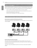
Страница 204: ...t The CH242 network error keeps occurring and disappearing in the ACP BACnet controller Case of incorrect connection of RS 485 communication line If each communication line is connected altogether as in the following figure the communication line must be separated PQNFB17C0 BACnet PI485 vu sXGGGYGGGZGGGG rzkv o PI485 vu sXGGGYGGGZGGGG rzkv o PI485 vu sXGGGYGGGZGGGG rzkv o PI485 vu sXGGGYGGGZGGGG r...

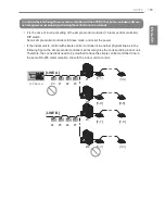
Страница 205: ...ode and reset the power If the indoor unit to control with simple central controller is in another physical line as in the following figure the simple central controller cannot recognize the corresponding indoor unit Therefore the connections need to be modified to have the simple central controller to be in the same RS 485 communication line with the indoor unit to control 0 6 3 0 LINE A LINE B 3...

Страница 206: ...nnection status of the communication line Normal communication line connection Wrong connection When the image ofWeb GUI is broken and you cannot see the screen such as the temperature well 1 Close Web GUI and rerun Caution y If PC is used for a long period of time or several application programs are used at the same time PC performance may be degraded and may affect the ACP BACnet UI y When you u...

Страница 207: ...L library glibc linuxthreads ncurses zlib If you request source code to LG Electronics through the following e mail we will send them in CD ROM with the payment necessary for medium and transportation da opensource lge com This suggestion is valid for 3 years after you received this product from LG Electronics You can receive the original GPL LGPL license from http www systemaircon com Part of the...

Страница 208: ...ropertyConditiona A Ƒ ReadPropertyConditional DS RPC B Data Sharing ReadPropertyConditiona B Ƒ ReadPropertyConditional DS WP A Data Sharing WriteProperty A Ƒ WriteProperty DS WP B Data Sharing WriteProperty B Ŷ WriteProperty DS WPM A Sharing WritePropertyMultiple A Ƒ WritePropertyMultiple DS WPM B Data Sharing WritePropertyMultiple B Ŷ WritePropertyMultiple DS COV A Data Sharing COV A Ƒ SubscribeC...

Страница 209: ... Initiate Execute DS COVP B Data Sharing COVP B Ƒ SubscribeCOV Confirmed COVNotification Unconfirmed COVNotification DS COVU A Data Sharing COV Unsolicited A Ƒ Unconfirmed COVNotification DS COVU B Data Sharing COV Unsolicited B Ƒ Unconfirmed COVNotification ...

Страница 210: ...ed EventNotification Unconfirmed EventNotification AE ACK A Alarm and Event ACK A Ƒ AcknowledgeAlarm AE ACK B Alarm and Event ACK B Ƒ AcknowledgeAlarm AE ASUM A Alarm and Event Summary A Ƒ GetAlarmSummary AE ASUM B Alarm and Event Summary B Ƒ GetAlarmSummary AE ESUM A Event Summary A Ƒ GetEnrollment Summary AE ESUM B Event Summary B Ƒ GetEnrollment Summary AE INFO A Alarm and Event Information A Ƒ...

Страница 211: ...al B shall support SCHED I B and DS WP A Ƒ Trending BIBBS ǹ 1RW VXSSRUWHG ȿ 6XSSRUW BIBB Type Supported ACP BACnet Service Initiate Execute T VMT A Trending Viewing and Modifying Trends A Ƒ ReadRange T VMT I B Trending Viewing and Modifying Trends Internal B Ƒ ReadRange T VMT E B Trending Viewing and Modifying Trends External B Ƒ ReadRange T ATR A Trending Automated Trend Retrieval A Ƒ ConfirmedEv...

Страница 212: ... Device Management DeviceCommunication Control B Ƒ DeviceCommunication Control DM PT A Device Management PrivateTransfer A Ƒ ConfirmedPrivate Transfer UnconfirmedPrivate Transfer DM PT B Device Management PrivateTransfer B Ƒ ConfirmedPrivate Transfer UnconfirmedPrivate Transfer DM TM A Device Management Text Message A Ƒ ConfirmedPrivate Transfer UnconfirmedPrivate Transfer DM TM B Device Managemen...

Страница 213: ... DM BR B Device Management Backup and Restore B Ƒ AtomicReadFile DMAtomicWriteFile ReinitializeDevice DM R A Device Management Restart A Ƒ Unconfimed COVNotification DM R B Device Management Restart B Ƒ Unconfimed COVNotification DM LM A Device Management List Manipulation A Ƒ AddListElement RemoveListElement DM LM B Device Management List Manipulation B Ƒ AddListElement RemoveListElement DM OCD A...

Страница 214: ... B Network Management Connection Establishment B Ƒ Establish Connection To Network Disconnect Connection To Network DM BR A Network Management Router Configuration A Ƒ Who Is Router To Network I Am Router To Network I Could Be Router To Network Initialize Routing Table Initialize Routing Table Ack NM RC B Network Management Router Configuration B Ƒ Who Is Router To Network I Am Router To Network I...

Страница 215: ...r_Of_States Unsigned R R State_Text QHW 55 1 RI CharacterString O Time_Delay Unsigned O3 Notification_Class Unsigned O3 Alarm_Values List of Unsigned O3 Fault_Values List of Unsigned O3 Event_Enable BACnetEventTransitionBits O3 Acked_Transitions BACnetEventTransitionBits O3 Notify_Type BACnetNotifyType O3 Event_Time_Stamps QHW 55 RI BACnetTimeStamp O3 Multi state Output Object Type Property Identi...

Страница 216: ...Of_States Unsigned R R State_Text QHW 55 1 RI CharacterString O Priority_Array BACnetPriorityArray R Relinquish_Default Unsigned R Time_Delay Unsigned O1 Notification_Class Unsigned O1 Feedback_Value Unsigned O1 Event_Enable BACnetEventTransitionBits O1 Acked_Transitions BACnetEventTransitionBits O1 Notify_Type BACnetNotifyType O1 Event_Time_Stamps QHW 55 RI BACnetTimeStamp O1 Profile_Name Charact...

Страница 217: ...10 registration items Resource 3 Other 0 An Event registration request of more than 10 registration items Resource 3 No_Space_To_Add_List_ OHPHQW Request for the deletion of an element not existing in the list Service 5 Other 0 Request for the execution of the AddListElement RemoveListElement for a property that is not of List type Service 5 Property_Is_Not_List 22 Reject PDU Reject PDU Reject Rea...

Страница 218: ...le to process due to too many requests beyond the capacity Buffer_Overflow 1 The processing of segments was aborted because an expected APDU was received Invalid_APDU_In_This_State 2 The response side does not support the segment Segmentation_Not_Supported 4 ...

Страница 219: ...rrect the interference at his own expense Caution Changes or modifications not expressly approved by the manufacturer responsible for compliance could void the user s authority to operate the equipment Disposal of your old appliance 1 When this crossed out wheeled bin symbol is attached to a product it PHDQV WKH SURGXFW LV FRYHUHG E WKH XURSHDQ LUHFWLYH 2 All electrical and electronic products sho...

Страница 220: ......
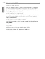
Отзывы: