


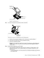


Step 6.
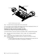
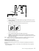
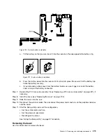
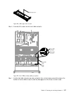
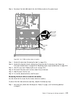
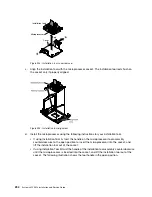
Reconnect the front USB cable to the front USB connector on the system board.
0000000000000000000000000000
0000000000000000000000000000
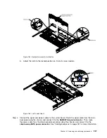
Figure 203. Front USB and video cables connection
Step 7.
Reinstall the bezel (see “Replacing the bezel” on page 275).
Step 8.
Reinstall the hard disk drives and drive bay filler panels into the drive bays (see “Replacing
hot-swap hard disk drives” on page 199 or “Replacing simple-swap hard disk drives” on page 202).
Step 9.
Install the cover (see “Replacing the cover” on page 190).
Step 10. Reconnect the power cords and any cables that you removed.
Step 11. Slide the server into the rack.
Step 12. Turn on the peripheral devices and the server.
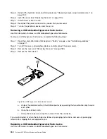
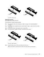
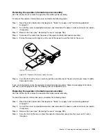
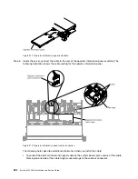
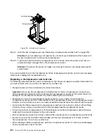
Removing the front video connector assembly
Use this information to remove the front video connector assembly.
To remove the front video connector assembly, complete the following steps:
Step 1.
Read the safety information that begins on “Safety” on page v and “Installation guidelines”
on page 31.
Removing and replacing components
279
Содержание x3550 M4
Страница 1: ...System x3550 M4 Installation and Service Guide Machine Type 7914 ...
Страница 6: ...iv System x3550 M4 Installation and Service Guide ...
Страница 178: ...164 System x3550 M4 Installation and Service Guide ...
Страница 322: ...308 System x3550 M4 Installation and Service Guide ...
Страница 828: ...814 System x3550 M4 Installation and Service Guide ...
Страница 986: ...972 System x3550 M4 Installation and Service Guide ...
Страница 990: ...976 System x3550 M4 Installation and Service Guide ...
Страница 1005: ......
Страница 1006: ......


