


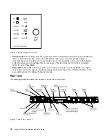


•
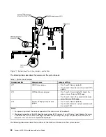
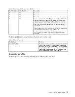
NMI button:
Press this button to force a nonmaskable interrupt to the microprocessor. It allows you to
blue screen the server and take a memory dump (use this button only when directed by the Lenovo
service support). You might have to use a pen or the end of a straightened paper clip to press the button.
The NMI button is in the lower left-hand corner on the rear of the server.
•
PCI slot 1:
Insert a low-profile PCI Express adapter into this slot.
•
PCI slot 2:
Insert a half-length, full-height PCI Express or PCI-X adapter into this slot.
•
Power connector:
Connect the power cord to this connector.
Note:
Power supply 1 is the default/primary power supply. If power supply 1 fails, you must replace it
immediately.
•
Video connector:
Connect a monitor to this connector. The video connectors on the front and rear of
the server can be used simultaneously.
Note:
The maximum video resolution is 1600 x 1200 at 75 Hz.
•
Serial connector:
Connect a 9-pin serial device to this connector. The serial port is shared with the
integrated management module II (IMM2). The IMM2 can take control of the shared serial port to redirect
serial traffic, using Serial over LAN (SOL).
•
USB connectors:
Connect a USB device, such as a USB mouse or keyboard to any of these connectors.
•
Systems-management Ethernet connector:
Use this connector to connect the server to a network for
full systems-management information control. This connector is used only by the integrated management
module (IMM2). A dedicated management network provides additional security by physically separating
the management network traffic from the production network. You can use the Setup utility to configure
the server to use a dedicated systems management network or a shared network.
•
Ethernet connectors:
Use either of these connectors to connect the server to a network. When you
enable shared Ethernet for IMM2 in the Setup utility, you can access the IMM2 using either the Ethernet 1
or the system-management Ethernet (default) connector.
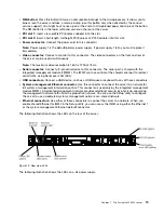
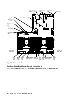
The following illustration shows the LEDs on the rear of the server.
00
00
00
00
00
00
00
000
000
000
000
00
00
000
000
000
000
000
00000
00000
Figure 12. Rear view LEDs
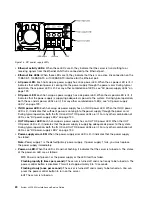
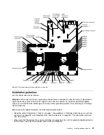
The following illustration shows the LEDs on a dc power supply.
19
Содержание x3550 M4
Страница 1: ...System x3550 M4 Installation and Service Guide Machine Type 7914 ...
Страница 6: ...iv System x3550 M4 Installation and Service Guide ...
Страница 178: ...164 System x3550 M4 Installation and Service Guide ...
Страница 322: ...308 System x3550 M4 Installation and Service Guide ...
Страница 828: ...814 System x3550 M4 Installation and Service Guide ...
Страница 986: ...972 System x3550 M4 Installation and Service Guide ...
Страница 990: ...976 System x3550 M4 Installation and Service Guide ...
Страница 1005: ......
Страница 1006: ......


