System board components
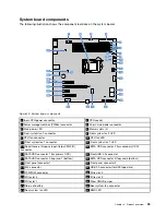
The following illustration shows the component locations on the system board.
Figure 20. System board components
1
8-pin CPU power connector
2
CPU socket
3
Power management bus (PMBus) connector
4
24-pin main power connector
5
Main power LED
6
Memory slots (4)
7
Front system fan 2 connector
8
Front system fan 2 LED
9
CPU fan connector
10
CPU fan LED
11
Front system fan 1 connector
12
Front system fan 1 LED
13
Serial General Purpose Input/Output (SGPIO)
connector
14
SATA ODD connector 2 (for secondary ODD)
15
SATA ODD connector 1 (for primary ODD)
16
Front USB 3.0 connector
17
SATA HDD connector 0 (top) and 1 (bottom)
18
SATA HDD connector 2 (top) and 3 (bottom)
19
Front panel connector 1
20
Front panel connector 2
21
M.2 connector
22
USB 2.0 connector (for RDX tape drive)
23
TPM/TCM connector
24
PCIe slot 4
25
PCIe slot 3
26
PCIe slot 2
27
PCIe slot 1
28
Clear CMOS jumper
29
Coin-cell battery
30
Rear system fan connector
31
Rear system fan LED
32
BMC LED
33
Содержание ThinkServer TS460
Страница 1: ...ThinkServer TS460 User Guide and Hardware Maintenance Manual Machine Types 70TQ 70TR 70TS and 70TT ...
Страница 14: ...xii ThinkServer TS460 User Guide and Hardware Maintenance Manual ...
Страница 18: ...4 ThinkServer TS460 User Guide and Hardware Maintenance Manual ...
Страница 52: ...38 ThinkServer TS460 User Guide and Hardware Maintenance Manual ...
Страница 68: ...54 ThinkServer TS460 User Guide and Hardware Maintenance Manual ...
Страница 138: ...124 ThinkServer TS460 User Guide and Hardware Maintenance Manual ...
Страница 144: ...130 ThinkServer TS460 User Guide and Hardware Maintenance Manual ...
Страница 148: ...134 ThinkServer TS460 User Guide and Hardware Maintenance Manual ...
Страница 159: ...Taiwan BSMI RoHS declaration Appendix C Restriction of Hazardous Substances RoHS Directive 145 ...
Страница 160: ...146 ThinkServer TS460 User Guide and Hardware Maintenance Manual ...
Страница 171: ......
Страница 172: ......


