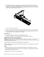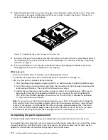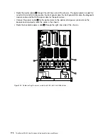
• Route the signal cables
1
through the left inner side of the chassis. The signal cables include the
mini-SAS to mini-SAS signal cable, the front panel cable, the front panel USB cable, the diagnostic
module cable, and the SATA signal cable for the optical drive.
• Connect the power cable
2
for the optical drive to the optical drive power connector on the
backplane and properly route the cable in the chassis.
• Route the backplane power cable
3
through the right inner side of the chassis.
Figure 132. Cable routing for server models with 3.5-inch hard disk drives
172
ThinkServer RD340 User Guide and Hardware Maintenance Manual
Содержание ThinkServer RD340
Страница 18: ...6 ThinkServer RD340 User Guide and Hardware Maintenance Manual ...
Страница 84: ...72 ThinkServer RD340 User Guide and Hardware Maintenance Manual ...
Страница 188: ...176 ThinkServer RD340 User Guide and Hardware Maintenance Manual ...
Страница 198: ...186 ThinkServer RD340 User Guide and Hardware Maintenance Manual ...
Страница 214: ...202 ThinkServer RD340 User Guide and Hardware Maintenance Manual ...
Страница 215: ......
Страница 216: ......


