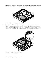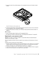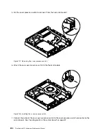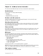
5. Pull the cover presence switch to remove it from the heat sink bracket.
Figure 197. Removing the cover presence switch
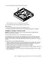
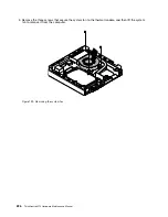
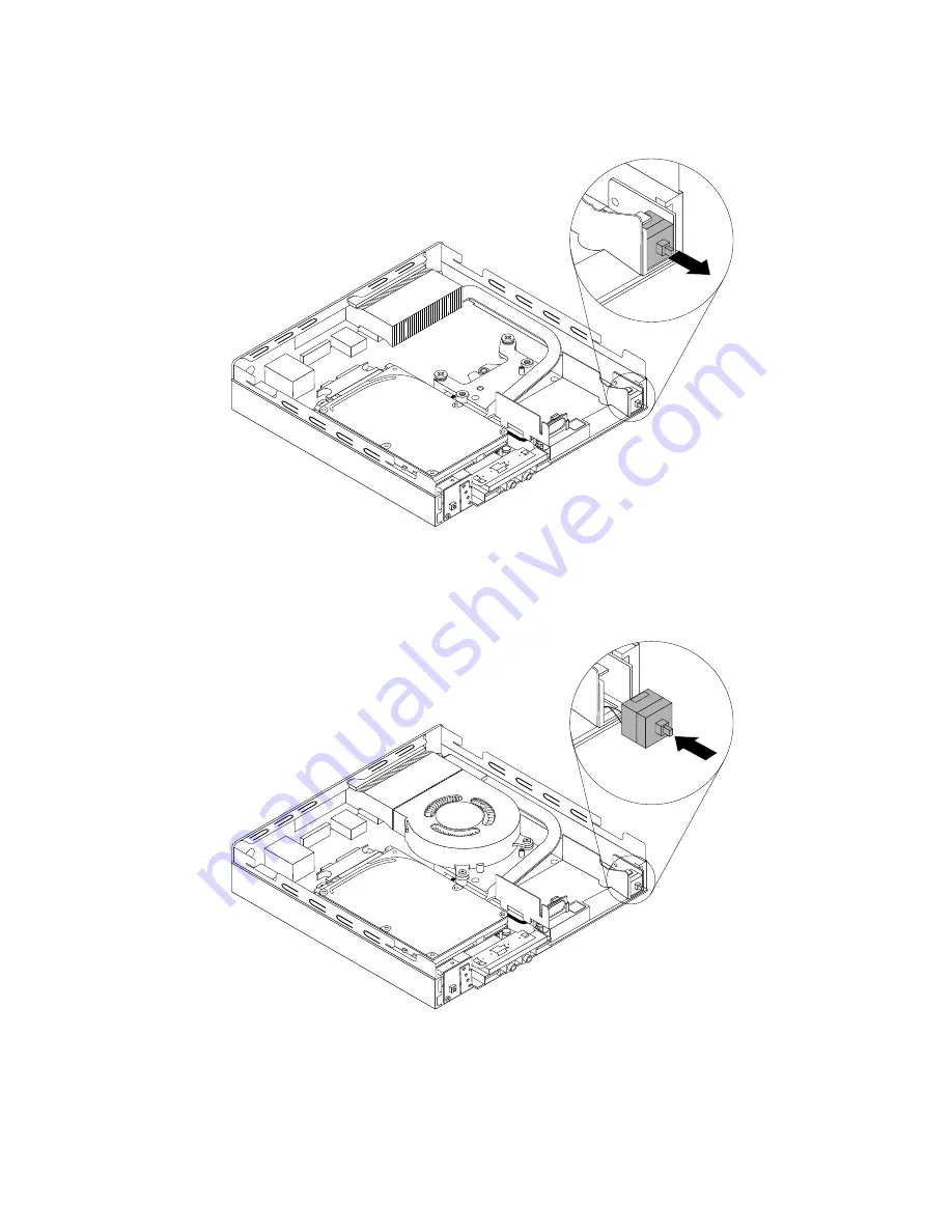
6. Attach the new cover presence switch to the thermal module.
Figure 198. Installing the cover presence switch
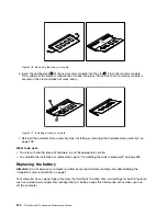
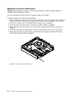
7. Connect the cable of the new cover presence switch to the cover presence switch connector on the
system board. See “Locating parts on the system board” on page 87.
224
ThinkCentre M73 Hardware Maintenance Manual
Содержание ThinkCentre M73 10B0
Страница 6: ...iv ThinkCentre M73 Hardware Maintenance Manual ...
Страница 8: ...2 ThinkCentre M73 Hardware Maintenance Manual ...
Страница 15: ...Chapter 2 Safety information 9 ...
Страница 19: ...Chapter 2 Safety information 13 ...
Страница 20: ...1 2 14 ThinkCentre M73 Hardware Maintenance Manual ...
Страница 21: ...1 2 Chapter 2 Safety information 15 ...
Страница 26: ...1 2 20 ThinkCentre M73 Hardware Maintenance Manual ...
Страница 27: ...1 2 Chapter 2 Safety information 21 ...
Страница 30: ...24 ThinkCentre M73 Hardware Maintenance Manual ...
Страница 34: ...28 ThinkCentre M73 Hardware Maintenance Manual ...
Страница 62: ...56 ThinkCentre M73 Hardware Maintenance Manual ...
Страница 74: ...68 ThinkCentre M73 Hardware Maintenance Manual ...
Страница 92: ...86 ThinkCentre M73 Hardware Maintenance Manual ...
Страница 140: ...134 ThinkCentre M73 Hardware Maintenance Manual ...
Страница 244: ...238 ThinkCentre M73 Hardware Maintenance Manual ...
Страница 248: ...242 ThinkCentre M73 Hardware Maintenance Manual ...
Страница 254: ...248 ThinkCentre M73 Hardware Maintenance Manual ...
Страница 255: ......
Страница 256: ......

