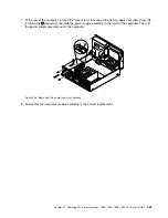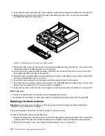
9. Install the new power supply assembly into the chassis so that the screw holes in the new power supply
assembly are aligned with the corresponding holes in the rear of the chassis. Then, install the three
screws to secure the new power supply assembly.
Note:
Use only screws provided by Lenovo.
Figure 107. Installing the power supply assembly
10. Connect the new power supply assembly cables to all drives and the system board. See “Locating
parts on the system board” on page 80.
162
ThinkCentre M73 Hardware Maintenance Manual
Содержание ThinkCentre M73 10B0
Страница 6: ...iv ThinkCentre M73 Hardware Maintenance Manual ...
Страница 8: ...2 ThinkCentre M73 Hardware Maintenance Manual ...
Страница 15: ...Chapter 2 Safety information 9 ...
Страница 19: ...Chapter 2 Safety information 13 ...
Страница 20: ...1 2 14 ThinkCentre M73 Hardware Maintenance Manual ...
Страница 21: ...1 2 Chapter 2 Safety information 15 ...
Страница 26: ...1 2 20 ThinkCentre M73 Hardware Maintenance Manual ...
Страница 27: ...1 2 Chapter 2 Safety information 21 ...
Страница 30: ...24 ThinkCentre M73 Hardware Maintenance Manual ...
Страница 34: ...28 ThinkCentre M73 Hardware Maintenance Manual ...
Страница 62: ...56 ThinkCentre M73 Hardware Maintenance Manual ...
Страница 74: ...68 ThinkCentre M73 Hardware Maintenance Manual ...
Страница 92: ...86 ThinkCentre M73 Hardware Maintenance Manual ...
Страница 140: ...134 ThinkCentre M73 Hardware Maintenance Manual ...
Страница 244: ...238 ThinkCentre M73 Hardware Maintenance Manual ...
Страница 248: ...242 ThinkCentre M73 Hardware Maintenance Manual ...
Страница 254: ...248 ThinkCentre M73 Hardware Maintenance Manual ...
Страница 255: ......
Страница 256: ......


