


Lake Shore Model 325 Temperature Controller User’s Manual
2-6
Cooling System Design
2.3.7
Lead Soldering
When additional wire is soldered to short sensor leads, care must be taken not to overheat the sensor. A heat sink such as
a metal wire clamp or alligator clip will heat sink the leads and protect the sensor. Leads should be tinned before bonding
to reduce the time that heat is applied to the sensor lead. Solder flux should be cleaned after soldering to prevent
corrosion.
2.3.8
Heat Sinking Leads
Sensor leads can be a significant source of error if they are not properly heat sinked. Heat will transfer down even small
leads and alter the sensor reading. The goal of heat sinking is to cool the leads to a temperature as close to the sensor as
possible. This can be accomplished by putting a significant length of lead wire in thermal contact with every cooled
surface between room temperature and the sensor. Lead wires can be adhered to cold surfaces with varnish over a thin
electrical insulator like cigarette paper. They can also be wound onto a bobbin that is firmly attached to the cold surface.
Some sensor packages include a heat sink bobbin and wrapped lead wires to simplify heat sinking.
2.3.9
Thermal Radiation
Thermal (black body) radiation is one of the ways heat is transferred. Warm surfaces radiate heat to cold surfaces even
through a vacuum. The difference in temperature between the surfaces is one thing that determines how much heat is
transferred. Thermal radiation causes thermal gradients and reduces measurement accuracy. Many cooling systems
include a radiation shield. The purpose of the shield is to surround the load, sample, and sensor with a surface that is at or
near their temperature to minimize radiation. The shield is exposed to the room temperature surface of the vacuum
shroud on its outer surface, so some cooling power must be directed to the shield to keep it near the load temperature.
If the cooling system does not include an integrated radiation shield (or one cannot be easily made), one alternative is to
wrap several layers of super-insulation (aluminized mylar) loosely between the vacuum shroud and load. This reduces
radiation transfer to the sample space.
2.4
HEATER SELECTION AND INSTALLATION
There is a variety of resistive heaters that can be used as the controlled heating source for temperature control. The
mostly metal alloys like nichrome are usually wire or foil. Shapes and sizes vary to permit installation into different
systems.
2.4.1
Heater Resistance and Power
Cryogenic cooling systems have a wide range of cooling power. The resistive heater must be able to provide sufficient
heating power to warm the system. The Model 325 can supply up to 25 W of power to a heater (if the heater resistance is
appropriate). The Model 325 heater output current source has a maximum output of 1 A at the 25
setting, or 0.71 A at
the 50
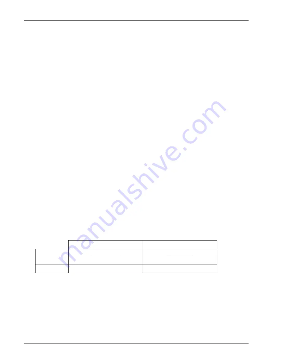
setting. Even though the Model 325 main heater output is a current source, it has a voltage limit (called the
compliance voltage) which is set to either 25 V or 35.4 V when the heater resistance is set to 25
or 50
, respectively.
This compliance voltage also limits maximum power.
Max Power (W) at 25
Setting
Max Power (W) at 50
Setting
Voltage Limit:
(25 V)
2
Resistance (
)
(35.4 V)
2
Resistance (
)
Current Limit:
(1 A)
2
× Resistance (
)
(0.71 A)
2
× Resistance (
)
Both limits are in place at the same time, so the smaller of the two computations gives the maximum power available to
the heater. A heater of 50
at the 50
setting allows the instrument to provide its maximum power of 25 W. A smaller
resistance of 40
at the 50
setting allows about 20 W of power, while a larger resistance of 60
is limited by
compliance voltage to about 21 W. The Model 325 is designed to limit the internal power dissipation as a measure of
self-protection. This internal power limit will not allow the output current to rise once the power limit is reached.
The resistor chosen as a heater must be able to withstand the power being dissipated in it. Pre-packaged resistors have a
power specification that is usually given for the resistor in free air. This power may need to be derated if used in a
vacuum where convection cooling cannot take place and it is not adequately heat sinked to a cooled surface.
Содержание 325
Страница 4: ...Lake Shore Model 325 Temperature Controller User s Manual...
Страница 6: ......
Страница 22: ...Lake Shore Model 325 Temperature Controller User s Manual 1 10 Introduction This Page Intentionally Left Blank...
Страница 47: ...Lake Shore Model 325 Temperature Controller User s Manual 3 11 This Page Intentionally Left Blank...
Страница 48: ...Lake Shore Model 325 Temperature Controller User s Manual 3 12 This Page Intentionally Left Blank...
Страница 76: ...Lake Shore Model 325 Temperature Controller User s Manual 4 28 Operation This Page Intentionally Left Blank...
Страница 122: ...Lake Shore Model 325 Temperature Controller User s Manual 6 36 Remote Operation This Page Intentionally Left Blank...
Страница 128: ...Lake Shore Model 325 Temperature Controller User s Manual 7 6 Options and Accessories...