278
Hydraulic System
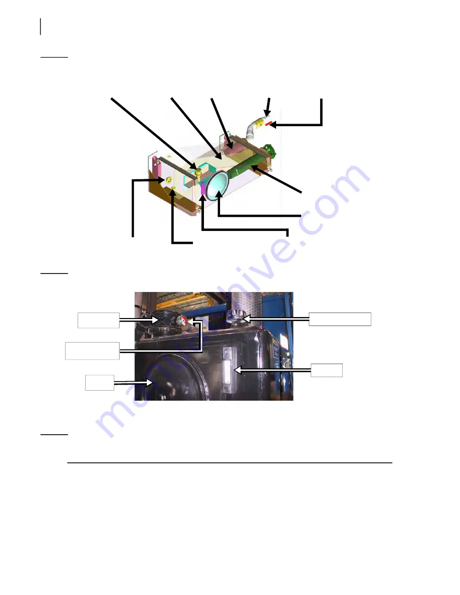
Figure 5
-
19 Hydraulic tank components (pressurized tank)
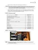
Figure 5
-
20 Hydraulic tank components (non-pressurized tank)
Pressurizing Tank System
N
OTE
:
For chassis-mounted tanks only. No pressurization is needed for behind-the-cab mounted
tanks (saddle model); gravity is enough to cause the oil to flow.
Cavitation inside the pump generates excessive wear and noise.
Shut-off valve
Suction line
Strainer
Baffle
Filter element
housing
Access cover
Drain plug
Oil heater plug
Filler/breather cap
Oil temp/
level gauge
Filler/breather cap
Oil gauge
Access
cover
Return filter
housing
Filter restriction
indicator
Содержание EXPERT
Страница 1: ...EXPERT TM MAINTENANCE MANUAL...
Страница 2: ......
Страница 3: ...EXPERT MAINTENANCE MANUAL...
Страница 10: ...viii Table of Contents...
Страница 18: ...8 Introduction...
Страница 244: ...234 General Maintenance...
Страница 251: ...Lubrication 241 Figure 4 11 Glass compartment lubrication chart optional...
Страница 252: ...242 Lubrication Figure 4 12 EXPERT lubrication chart...
Страница 261: ...Lubrication 251 Figure 4 27 Packer lubrication points 2 Grease fitting LH side front cylinder pin...
Страница 263: ...Lubrication 253 Pump Drive Shaft U Joint Figure 4 30 Pump drive shaft lubrication points Grease fittings...
Страница 264: ...254 Lubrication...
Страница 320: ...310 Hydraulic System...
Страница 357: ...Troubleshooting 349...
Страница 358: ...350 Troubleshooting...
Страница 386: ...378 Multiplexing...
Страница 388: ...380 Lifting Arms Figure 10 1 Mounting bolts Figure 10 2 Wear pads Figure 10 3 Helping Hand gripper...


