


Pneumatic System
323
• The gauge should read a minimum of 90 PSI.
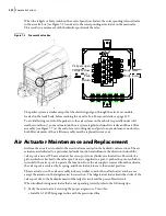
Verify the opposite port of the air actuator is not plugged. To do this:
• Remove the air line from the air actuator and operate.
Verify that the air pressure inside the air actuator is not bypassing internally by following these
simple steps:
• Remove both air lines from the air actuator.
• Apply shop air to one side of the air actuator while feeling/listening for air exhausting from the
opposite port of the air actuator. Repeat in both directions.
• If air is bypassing, service or replacement of the air actuator is necessary.
Ensure the inside of the air actuator is free from debris and damage. Clean with a lint-free rag and
lightly lubricate with Parker’s Super-O-Lube or a silicon-based equivalent.
Labrie
Plus
offers a seal kit to replace the internal seals in the actuator. Contact Labrie
Plus
for more
details.
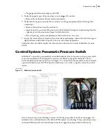
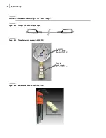
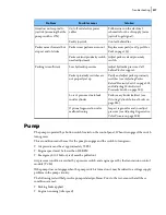
Control System Pneumatic Pressure Switch
All E
XPERT
™ units with a pneumatically controlled hydraulic valve incorporate an air pressure switch
to provide confirmation that adequate air pressure is available to engage the hydraulics. This is
located inside the pneumatic valve box (see Figure 7
2), on the Mac valve manifold, and is a normally
open switch that closes at 90 PSI. When this switch closes, a 12 volt (+) signal is sent to the control
system.
Figure 7
-
3 Main air pressure switch
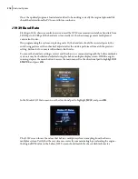
Prior to chassis air pressure building to at least 90 PSI, the pump will not be allowed to engage. On
multiplex units, a yellow banner on the Labrie IFM display screen showing “Pump: main air pressure”
and an audible beep will occur if an attempt is made to engage the pump without sufficient air
Содержание EXPERT
Страница 1: ...EXPERT TM MAINTENANCE MANUAL...
Страница 2: ......
Страница 3: ...EXPERT MAINTENANCE MANUAL...
Страница 10: ...viii Table of Contents...
Страница 18: ...8 Introduction...
Страница 244: ...234 General Maintenance...
Страница 251: ...Lubrication 241 Figure 4 11 Glass compartment lubrication chart optional...
Страница 252: ...242 Lubrication Figure 4 12 EXPERT lubrication chart...
Страница 261: ...Lubrication 251 Figure 4 27 Packer lubrication points 2 Grease fitting LH side front cylinder pin...
Страница 263: ...Lubrication 253 Pump Drive Shaft U Joint Figure 4 30 Pump drive shaft lubrication points Grease fittings...
Страница 264: ...254 Lubrication...
Страница 320: ...310 Hydraulic System...
Страница 357: ...Troubleshooting 349...
Страница 358: ...350 Troubleshooting...
Страница 386: ...378 Multiplexing...
Страница 388: ...380 Lifting Arms Figure 10 1 Mounting bolts Figure 10 2 Wear pads Figure 10 3 Helping Hand gripper...


