322
Pneumatic System
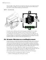
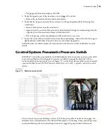
When the tailgate or body switch on the control panel is activated, the corresponding solenoid valve
in the air valve box (see Figure 7
2) sends air to the corresponding air actuator on the main valve.
This results in a movement of the hydraulic spool inside the valve.
Figure 7
-
2 Pneumatic valve box
The packer system is similar except that the electric signal goes through the electronic module,
located on the truck body, before reaching the air valve box. For more details, see page 329.
To avoid affecting control of the packer or other air systems on the vehicle (especially under cold
weather conditions), you must maintain the air system regularly: drain all air tanks and the air filter
assembly (see Figure 7
7) at the end of every working day and prior to any maintenance work. Also,
both filter elements of the air filter assembly must be replaced twice a year.
Air Actuator Maintenance and Replacement
Air from the air valves is routed to the air actuators mounted on the hydraulic valve sections. The air
actuators are dedicated to a particular hydraulic function and influence the direction in which the
valve spool is moved. The air actuators have two ports in a cylinder case located on either side of a
piston, which is attached to the valve spool. As air is supplied to a port, it pushes the piston, which in
turn, shifts the valve spool to operate the function. Once the air supply is removed from the actuator,
the valve spool is centered by its spring, and the actuator returns to the neutral position.
The air actuators on the valve assembly look very similar to each other; all actuators are the same
except the actuator on the tailgate raise/lower section. The tailgate air actuator limits the stroke of the
valve spool due to the hydraulic needs of the tailgate circuit and the power-bleed circuit.
When troubleshooting an actuator that is not operating correctly, refer to the following tips:
Verify the air actuator is receiving the proper air pressure. To do this:
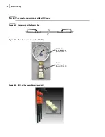
• Install a 0-150 PSI air gauge in-line with the pressurized line.
Body lower
Body raise
Tailgate open
Tailgate close
Pack
Return
Содержание EXPERT
Страница 1: ...EXPERT TM MAINTENANCE MANUAL...
Страница 2: ......
Страница 3: ...EXPERT MAINTENANCE MANUAL...
Страница 10: ...viii Table of Contents...
Страница 18: ...8 Introduction...
Страница 244: ...234 General Maintenance...
Страница 251: ...Lubrication 241 Figure 4 11 Glass compartment lubrication chart optional...
Страница 252: ...242 Lubrication Figure 4 12 EXPERT lubrication chart...
Страница 261: ...Lubrication 251 Figure 4 27 Packer lubrication points 2 Grease fitting LH side front cylinder pin...
Страница 263: ...Lubrication 253 Pump Drive Shaft U Joint Figure 4 30 Pump drive shaft lubrication points Grease fittings...
Страница 264: ...254 Lubrication...
Страница 320: ...310 Hydraulic System...
Страница 357: ...Troubleshooting 349...
Страница 358: ...350 Troubleshooting...
Страница 386: ...378 Multiplexing...
Страница 388: ...380 Lifting Arms Figure 10 1 Mounting bolts Figure 10 2 Wear pads Figure 10 3 Helping Hand gripper...


