


402
Lifting Arms
7.
Once done, reinstall the gripper adjustment rod. To do so:
7 a.
Reinstall the end section of the adjustment rod that contains the bushing/spacer system.
7 b.
Reinstall the pin with the bolt to secure the rod to the gripper base.
7 c.
Tighten the bolt properly.
7 d.
Move the two-finger section of the gripper to the position it was in before step 4.
7 e.
If needed, adjust the length of the adjustment rod (see steps 12-13).
7 f.
Once done, retighten the locknut and push the gripper adjustment rod end into place.
7 g.
Reinstall the pin with the bolt.
7 h.
Tighten the bolt properly.
8.
Lubricate both adjustment rod ends using the grease fittings.
9.
Test the adjustment to make sure the gripper opens and closes properly. Repeat the adjustment
procedure if necessary.
Gripper Arm Pivot Bushing Installation
When installing replacement bushings into H
ELPING
-H
AND
™ gripper arm pivots, the replacement
bushing will slightly compress when pressed into the gripper pivot weldment.
It is normal practice that new bushings may require honing of the inside diameter to allow the pin to
pass through freely. When honing, please keep in mind that the suggested clearance between the
bushing and pin is 0.002” – do not hone the bushings excessively.
Gripper Height Setting
Gripper height is preset in factory; however, there are two possible height settings: lower and upper
positions.
To move the gripper to
upper/lower position
, do the following:
1.
Use appropriate hardware to secure the gripper.
2.
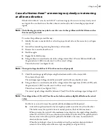
Remove all 3 horizontal bolts from the gripper head (see Figure 10
30).
Figure 10
-
30 Gripper head
3.
Remove all 3 vertical bolts.
Spill shield
(optional)
Bolts
Gripper head
Содержание EXPERT
Страница 1: ...EXPERT TM MAINTENANCE MANUAL...
Страница 2: ......
Страница 3: ...EXPERT MAINTENANCE MANUAL...
Страница 10: ...viii Table of Contents...
Страница 18: ...8 Introduction...
Страница 244: ...234 General Maintenance...
Страница 251: ...Lubrication 241 Figure 4 11 Glass compartment lubrication chart optional...
Страница 252: ...242 Lubrication Figure 4 12 EXPERT lubrication chart...
Страница 261: ...Lubrication 251 Figure 4 27 Packer lubrication points 2 Grease fitting LH side front cylinder pin...
Страница 263: ...Lubrication 253 Pump Drive Shaft U Joint Figure 4 30 Pump drive shaft lubrication points Grease fittings...
Страница 264: ...254 Lubrication...
Страница 320: ...310 Hydraulic System...
Страница 357: ...Troubleshooting 349...
Страница 358: ...350 Troubleshooting...
Страница 386: ...378 Multiplexing...
Страница 388: ...380 Lifting Arms Figure 10 1 Mounting bolts Figure 10 2 Wear pads Figure 10 3 Helping Hand gripper...


