320
Electrical System
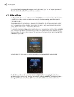
1) Turn the ignition switch to the “run” position, activating the IFM display.
2) On the IFM display, select “Menu”, then select “I/O Status”.
3) Using the up/down arrows on the directional pad, scroll down and select “Others”.
4) The real-time supply voltages of the control modules (Nodes) will be displayed:
If voltage(s) are below 12 volts, check the supply power to the module; if all voltages are below
12 volts, check the chassis battery voltage.
This helps diagnose error messages such as a module disconnected or functions of a module not
receiving their outputs. Once the supply voltages have been verified, further troubleshooting of
various outputs may then be investigated.
Содержание EXPERT
Страница 1: ...EXPERT TM MAINTENANCE MANUAL...
Страница 2: ......
Страница 3: ...EXPERT MAINTENANCE MANUAL...
Страница 10: ...viii Table of Contents...
Страница 18: ...8 Introduction...
Страница 244: ...234 General Maintenance...
Страница 251: ...Lubrication 241 Figure 4 11 Glass compartment lubrication chart optional...
Страница 252: ...242 Lubrication Figure 4 12 EXPERT lubrication chart...
Страница 261: ...Lubrication 251 Figure 4 27 Packer lubrication points 2 Grease fitting LH side front cylinder pin...
Страница 263: ...Lubrication 253 Pump Drive Shaft U Joint Figure 4 30 Pump drive shaft lubrication points Grease fittings...
Страница 264: ...254 Lubrication...
Страница 320: ...310 Hydraulic System...
Страница 357: ...Troubleshooting 349...
Страница 358: ...350 Troubleshooting...
Страница 386: ...378 Multiplexing...
Страница 388: ...380 Lifting Arms Figure 10 1 Mounting bolts Figure 10 2 Wear pads Figure 10 3 Helping Hand gripper...


