152
General Maintenance
Figure 3
-
209 Transversal beam
13.
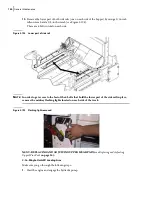
Remove the upper part of both side rails (one on each side of the hopper) [see Figure 3
210].
4 bolts are to be taken out to remove this section of the side rail.
Figure 3
-
210 Side rail
14.
Start the engine and engage the hydraulic pump.
15.
Extend the packer to mid-stroke position.
16.
Turn OFF the hydraulic pump and the engine.
17.
Lock out and tag out the vehicle (see
Locking Out and Tagging Out the Vehicle
18.
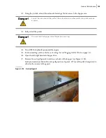
Remove the arm stopper.
Before removing it, make sure you mark down the arm stopper location with a pen.
Danger!
Do not enter the hopper while the packer is moving.
Side rail
Bolts that hold the
upper part of the
side rail in place
Содержание EXPERT
Страница 1: ...EXPERT TM MAINTENANCE MANUAL...
Страница 2: ......
Страница 3: ...EXPERT MAINTENANCE MANUAL...
Страница 10: ...viii Table of Contents...
Страница 18: ...8 Introduction...
Страница 244: ...234 General Maintenance...
Страница 251: ...Lubrication 241 Figure 4 11 Glass compartment lubrication chart optional...
Страница 252: ...242 Lubrication Figure 4 12 EXPERT lubrication chart...
Страница 261: ...Lubrication 251 Figure 4 27 Packer lubrication points 2 Grease fitting LH side front cylinder pin...
Страница 263: ...Lubrication 253 Pump Drive Shaft U Joint Figure 4 30 Pump drive shaft lubrication points Grease fittings...
Страница 264: ...254 Lubrication...
Страница 320: ...310 Hydraulic System...
Страница 357: ...Troubleshooting 349...
Страница 358: ...350 Troubleshooting...
Страница 386: ...378 Multiplexing...
Страница 388: ...380 Lifting Arms Figure 10 1 Mounting bolts Figure 10 2 Wear pads Figure 10 3 Helping Hand gripper...


