5
B1
A2
DP
OPT1
4
4
A
6
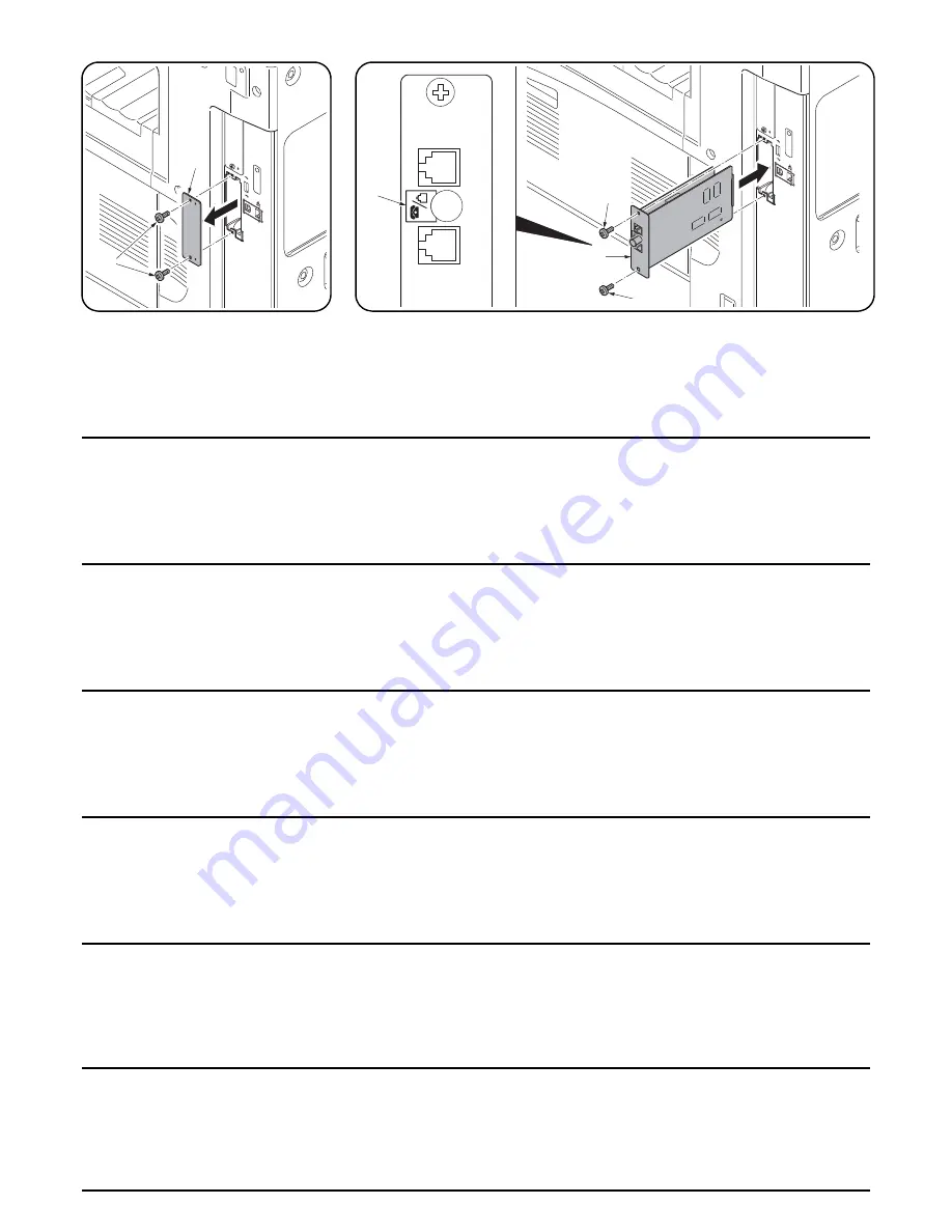
Remove the cover.
4.
Remove two screws (4) and then remove
OPT1 cover (5).
Install the FAX circuit board.
5.
Insert the FAX circuit board (A) along the groove in OPT1 and secure the board with two screws
(4) that have been removed in step 4.
Do not directly touch the FAX circuit board (A) terminal. Hold the top and bottom of the FAX
circuit board, or the projection of the board to insert the FAX circuit board (A).
Direct the label (6) on to the FAX circuit board (A) as indicated in the illustration and insert the
board along the groove.
Retirer le couvercle.
4.
Retirer les deux vis (4), puis le couvercle
OPT1 (5).
Installer la carte à circuits FAX.
5.
Insérer la carte à circuits FAX (A) le long de la rainure dans l’OPT1 et la fixer à l’aide des deux
vis (4) retirées à l’étape 4.
Ne pas toucher directement la borne de la carte à circuits FAX (A). Tenir les parties inférieure et
supérieure de la carte à circuits FAX ou la saillie de la carte pour insérer la carte à circuits FAX
(A).
Orienter l'étiquette (6) de la carte à circuits FAX (A) comme illustré et insérer la plaquette le long
de la rainure.
Desmonte la cubierta.
4.
Quite dos tornillos (4) y desmonte la cubierta
OPT1 (5).
Instale la tarjeta de circuitos de fax.
5.
Inserte la tarjeta de circuitos de fax (A) a lo largo de la ranura de OPT1 y asegúrela con los dos
tornillos (4) que ha quitado en el paso 4.
No toque directamente el terminal de la tarjeta de circuitos del fax (A). Sujete las partes superior
e inferior de la tarjeta de circuitos de fax o la saliente de la tarjeta para insertar la tarjeta de
circuitos de fax (A).
Oriente la etiqueta (6) en la tarjeta de circuitos del FAX (A) como se indica en la ilustración e
inserte la tarjeta a lo largo de la ranura.
Entfernen der Abdeckung.
4.
Die beiden Schrauben (4) herausdrehen und
Abdeckung OPT1 (5) abnehmen.
Einbauen der FAX-Leiterplatte.
5.
FAX-Leiterplatte (A) in die Nut des Einbauschachts OPT1 einsetzen und Leiterplatte mit den in
Schritt 4 ausgebauten Schrauben (4) befestigen.
Berühren Sie die Anschlüsse der FAX-Platine (A) nicht mit den Fingern. Die FAX-Leiterplatte
(A) bein Einsetzen oben und unten oder an dem Vorsprung festhalten.
Die FAX-Leiterplatte (A) so in die Nut einsetzen, dass der Aufkleber (6) wie abgebildet zur
Leiterplatte zeigt.
Rimuovere il coperchio.
4.
Rimuovere le due viti (4), quindi rimuovere il
coperchio OPT1 (5).
Montaggio della scheda a circuiti FAX.
5.
Inserire la scheda a circuiti FAX (A) lungo l’incavo nell’OPT1 e fissare la scheda con le due viti
(4) rimosse nell’operazione 4.
Non toccare direttamente il terminale della scheda a circuiti FAX (A). Per inserire il circuito FAX
(A), tenere l’estremit superiore e la base della scheda a circuiti FAX, o la sporgenza della
scheda a circuiti FAX.
Orientare l'etichetta (6) sulla scheda a circuiti FAX (A) come indicato nell'illustrazione e inserire
la scheda lungo l'incavo.
カバーの取り外し
4. ビス (4)2 本を外し、OPT1 のカバー(5) を取
り外す。
FAX 基板の取り付け
5. OPT1 の溝に沿って FAX 基板 (A) を挿入し、
手順 4 で外したビス (4)2 本で固定する。
FAX 基板 (A) の端子に直接触れないこと。FAX 基板 (A) の挿入時は基板の上下か突起を持つこ
と。
FAX 基板 (A) は、貼り付けられているラベル (6) が図に示す方向になるように、挿入すること。
拆下盖板
4.
拆下
2
颗螺钉
(4)
,然后拆下
OPT1
盖板
(5)
。
安装传真电路板
5.
沿着
OPT1
的沟槽插入传真电路板
(A)
并用在步骤
4
中拆下的两颗螺钉
(4)
固定电路板。
请勿直接触摸传真电路板
(A)
端子。按住传真电路板的顶部和底部,或者按住电路板的突出部将
传真电路板
(A)
插入。
将传真电路板
(A)
上的标签
(6)
保持图示中的方向,将电路板沿着沟槽方向插入。
B1
A2
DP
OPT1
4
5
Содержание TASKALFA 300I
Страница 1: ...SERVICE MANUAL Published in February 2010 842K5111 2K5SM061 Rev 1 TASKalfa 300i ...
Страница 4: ...This page is intentionally left blank ...
Страница 10: ...This page is intentionally left blank ...
Страница 14: ...2K5 This page is intentionally left blank ...
Страница 22: ...2K5 1 1 8 This page is intentionally left blank ...
Страница 196: ...2K5 1 4 52 This page is intentionally left blank ...
Страница 252: ...2K5 1 5 56 This page is intentionally left blank ...
Страница 274: ...2K5 2 1 20 This page is intentionally left blank ...
Страница 280: ...2K5 2 2 6 16 Operation fan motor OFM Cools the operation section 17 Eject fan motor EFM Cools the eject section ...
Страница 310: ...2K5 2 3 28 This page is intentionally left blank ...
Страница 347: ...INSTALLATION GUIDE FOR PAPER FEEDER ...
Страница 369: ...INSTALLATION GUIDE FOR BUILT IN FINISHER ...
Страница 381: ...INSTALLATION GUIDE FOR JOB SEPARATOR ...
Страница 391: ...INSTALLATION GUIDE FOR FAX System ...
Страница 407: ......
Страница 408: ......


