80
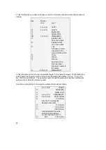
To test the frequency, connect a frequency meter to the pulse output terminals and proceed as
follows:
To test the pulse output, connect an external counter to the output terminals. When testing the
pulse output, the operator has the choice of the following pulse widths: 0.4 ms, 1.0 ms, 10.0
ms, 100.0 ms and 500 ms. The operator should choose the pulse width that best matches the
performance of his external pulse counter.
Connect a pulse counter to the impulse output and proceed as follows:
Fct. 2.(3).0
TEST P
→
SURE (NO)
↑
SURE (YES)
↵
Fct. 2.3.(1)
FREQUENCY
↑
Fct. 2.3.(2)
TEST PULSE
→
(0.4 mSec)
Use the
↑
to select the
desired pulse width
↑
(1.0 mSec)
↑
(10.0 mSec)
↑
(100.0 mSec)
Having selected the pulse
width zero the external
counter and then press
↵
↵
625
100.0 mSec
Key
Display
line 1
line 2
Fct. 2.(2)
TEST I
↑
Fct. 2.(3)
TEST P
→
SURE (NO)
↑
SURE (YES)
↵↵
Fct. 2.3.(1)
FREQUENCY
→
(LEVEL LOW)
0V on the output
↑
(LEVEL HIGH)
+V on the output
↑
1 Hz
A frequency meter
connected to the
output will show 1Hz.
↑
10 Hz
↑
100 Hz
↑
1000 Hz
After testing the
1000 Hz signal
connect a counter to
the output.
↵
Fct.2.3.(1)
FREQUENCY


