93
10-Pin Sensor Connector “C“ (Connector between primary and converter)
wh
it
e
gray
green
open
yel
lo
w
red
bl
ue
open*
bl
ac
k
vi
ol
et
* except for CE versions of wall mount configurations; this terminal used for ground
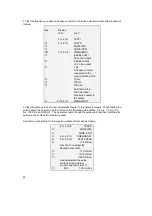
Testing the resistance values of
the sensors and exciter (compact
systems)
Typical values
(ohm)
Assesment of
measured values
1
Measuring tube driver:
Measure between violet and
black
P-Series
Std. 41 - 50
Ex II b 41 - 50
Ex II c 62 - 73
E-Series
Std. 71 - 87
Ex II c 262 - 296
2
To check sensor A and B:
Measure between:
white* and green
(Sensor A)
gray* and green
(Sensor B)
white and gray
(Sensors A and B)
P-Series E-Series
5-10 35-44
5-10 35-44
10-18 71-87
Measurements outside
typical values:
Primary faulty
Replace or call Krohne service.
3
To check the temperature
sensor (RTD):
Measure between:
red and yellow
red and blue
yellow and blue
P- and E-Series
80 - 180
1 - 2 **
80 - 180
Measurements inside typical
values:
Sensor OK
* For remote mounted converters, the wire colors gray and green are interchanged on the
converter connection compartment
** Values will be higher for remote converters depending on cable length
9.9
Status Warnings
The MFC 081 can detect a number of anomalous conditions during operation. These are
classed into four groups as follows :
LIGHT
These include :
–
Mass flow >2x primary head rating.
–
Temperature outside operating range
–
Mass total overflow.
Typically these indicate a problem with the use of the instrument, not the instrument itself.


