


Chapter 15 DRYPRO 832 Utility Tool
15-10
3
Set each item according to the status of use in the facility.
4
Click the [SAVE] button.
Save the changes and close the “PRINT CONDITION” to return to the DRYPRO 832 Utility Tool Maintenance
Menu window.
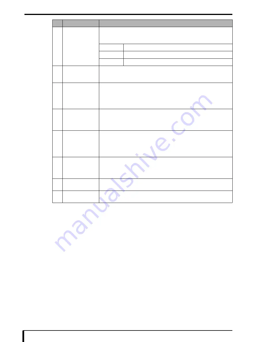
3
REQUESTED
IMAGE SIZE
STAMP
Set the position of the stamp of the reduction ratio to be printed when image size
specified from the diagnostic device exceeds the film size.
Default value: OFF
LEFT
Stamp is printed on the left edge of the film.
RIGHT
Stamp is printed on the right edge of the film.
OFF
Stamp is not printed.
4
INTEGRAL
MULTIPLE RATIO
Set the enlargement factor.
Setting range
:
1-15
Default value
:
1
5
PATIENT INFO.
POSITION
Set the position for the patient information to be printed (position from the bottom
edge of the film).
Default value
:
880
For more information, see
“
Printing positions of logo, patient information, and
stamp characters (Page 15-11)”
.
6
PATIENT INFO.
SIZE
Set the patient information print size (character height).
Default value
:
330
For more information, see
“
Printing positions of logo, patient information, and
stamp characters (Page 15-11)”
.
7
STAMP
POSITION
Set the position of the stamp to be printed (position from the bottom edge of the
film).
Default value
:
530
For more information, see
“
Printing positions of logo, patient information, and
stamp characters (Page 15-11)”
.
8
STAMP
SIZE
Set the stamp print size (character height).
Default value
:
330
For more information, see
“
Printing positions of logo, patient information, and
stamp characters (Page 15-11)”
.
9
[SAVE] button
Save the changes and close the
“
PRINT CONDITION
”
to return to the DRYPRO
832 Utility Tool Maintenance Menu window.
10
[BACK] button
Discard the changes and close the
“
PRINT CONDITION
”
to return to the DRYPRO
832 Utility Tool Maintenance Menu window.
No.
Setup Items
Description of Setting
Содержание Drypro 832
Страница 2: ......
Страница 12: ......
Страница 15: ...Chapter 1 Safety Precautions and Warnings 1 3 5 Laser Power Label No Precautions Warning Labels ...
Страница 22: ......
Страница 28: ......
Страница 74: ......
Страница 118: ......
Страница 228: ......
Страница 242: ......
Страница 260: ...Chapter 14 Setting and Adjustment 14 4 6 Click the PRINT button The ST13A PATTERN is printed Example ST13A PATTERN ...
Страница 263: ...Chapter 14 Setting and Adjustment 14 7 12 Click the PRINT button The ST13B PATTERN is printed Example ST13B PATTERN ...
Страница 265: ...Chapter 14 Setting and Adjustment 14 9 16 Click the PRINT button The ST13C PATTERN is printed Example ST13C PATTERN ...
Страница 388: ......
Страница 498: ......
Страница 521: ...18 23 18 5 Block Diagram ...
Страница 527: ...18 29 18 7 Printing Operation Load Timing Chart Standard 1 ch ...
Страница 529: ......


