


28
Click on the On or Off (2) buttons for the outputs as appropriate.
When you have made your selection click on OK (3) and the commands will appear in the symbol in
the edit area.
Although the selection panel alters according to which symbol and level is selected, it always follows a
similar format:
The command is built up by clicking on buttons.
As the command is built up, the choices selected so far are displayed in the text line at the top of the
selection panel.
With some panels there is an option to enter data using the keyboard (i.e. when manipulating
variables).
To delete a symbol – if the Selection tool isn’t already active, click to select. Click on the
symbol (it will highlight to show it is selected) and click on the Delete icon.
Connecting the symbols
The next stage is to connect the symbols in the edit area together to show the order in which each
symbol (command) should be carried out (the direction of the flowchart):
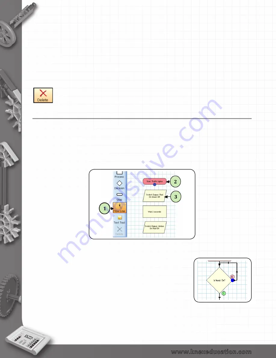
1) Click on the Flow Line icon (1).
2) Click on the first symbol (2) (usually Start), a blue dot will mark the connect point.
3) Click on the symbol next in the sequence (3). The program will automatically draw the flow line
between them (it will try to avoid other symbols and lines where possible).
4) Repeat this process until all of the symbols are connected.
To deselect the Flow Line tool: either click back on the Flow Line icon or click on the Selection icon.
Flow lines from a Decision symbol
A Decision symbol has 2 flow lines, a YES and a NO line. The first line
that will be drawn is from the base of the decision symbol.
The line from the base of the symbol is normally the YES line, the line
from the right is the NO line. To swap these over, make sure the Selection
tool is active, and double click on the decision symbol and they will
automatically swap over.
back to Table of Contents


